SlideShare ist ein Scribd-Unternehmen logo
1 von 24
1 2 3 4 5 6 7 8 9 10 11 12 13 14 15 16 17 18 19 20 21 22 23 24


6.6 Torque on a coil
6.6.1 Formula of torque
   Consider a rectangular coil (loop) of wire with side lengths a and
    b that it can turn about axis PQ. The coil is in a magnetic field of
    flux density B and the plane of the coil makes an angle θ with
    the direction of the magnetic field. A current I is flowing round
    the coil as shown in Figure 6.31.


                                                   1
1 2 3 4 5 6 7 8 9 10 11 12 13 14 15 16 17 18 19 20 21 22 23 24


                                       
                   B                    B   
                                            F1
           
           F
                        I
                             I
                  P           B
                            A φ θ

                                 b
                            B                        
                                                     B
                                                        
                   F1       a       I        Q           F
                                                 I


                       Figure 6.31a
                                                     2
1 2 3 4 5 6 7 8 9 10 11 12 13 14 15 16 17 18 19 20 21 22 23 24

                                              
                                              B

                                                               
                                                               F1
                                  B
                      A
                                      θ
                              φ                   b
                                                   sin φ
rotation          B                               2
                      b
                                          φ                          rotation

                      2           Q               b
                                                   sin φ
      F1                  φ                       2
                  Figure 6.31b: side view
     From the Figure 6.31b, the magnitude of the force F1 is given by
           F1 = IlB sin 90 and l = a
           F1 = IaB
     From the Figure 6.31a, the forces F lie along the axis PQ.
                                                            3
1 2 3 4 5 6 7 8 9 10 11 12 13 14 15 16 17 18 19 20 21 22 23 24


   From the Figure 6.31a, the forces F lie along the axis PQ.
   The resultant force on the coil is zero but the nett torque is
    not zero because the forces F1 are perpendicular to the axis PQ
    as shown in Figure 6.31a.
   The forces F1 cause the coil to rotate in the clockwise
    direction about the axis PQ as shown in Figure 6.31b.
   The magnitude of the nett torque about the axis PQ (refer to
    Figure 6.31b) is given by
                        b            b      
               τ = − F1  sin φ  − F1  sin φ 
                        2            2      
                         b        and F = IaB
                 = −2 F1  sin φ         1
                         2       
                             b      
                 = −2( IaB )  sin φ 
                             2      
                 = − IabB sin φ and ab = A(area of coil)
                                                   4
1 2 3 4 5 6 7 8 9 10 11 12 13 14 15 16 17 18 19 20 21 22 23 24


                τ = IAB sin φ
         since φ = 90 − θ thus
                        


                                 (
                 τ = IAB sin 90 − θ   )
                 τ = IAB cos θ
   For a coil of N turns, the magnitude of the torque is given by

                  τ = NIAB sin φ                     (6.14)

                            OR

                  τ = NIAB cos θ                     (6.15)

         where τ : torque on the coil
                 B : magnetic flux density
                 I : current flows in the coil       
                 φ : angle between vector area A and B       
                 θ : angle between the plane of the coil and B
                 N : number of turns (coils) 5
1 2 3 4 5 6 7 8 9 10 11 12 13 14 15 16 17 18 19 20 21 22 23 24


   From the eq. (6.14), thus the formula of torque in the vector form
    is given by
                     
                              (
                              
                     τ = NI A × B      )                  (6.16)

   The torque is zero when θ = 90° or φ = 0° and is maximum
    when θ = 0°  φ = 90° as shown in Figures 6.32a and 6.32b.
                or
                A                         
    B                                      B
                          θ = 90                     φ = 90
                                                          
                                                            A
                          φ =0    
                                                   θ = 0
        Figure 6.32a                           Figure 6.32b

    τ = NIAB sin 0       plane of the coil    τ = NIAB sin 90
          OR                                        OR
    τ = NIAB cos 90                           τ = NIAB cos 0
     τ =0                                  τ max = NIAB
                                                    6
1 2 3 4 5 6 7 8 9 10 11 12 13 14 15 16 17 18 19 20 21 22 23 24


   In a radial field, the plane of the coil is always parallel to the
                field
    magnetic field for any orientation of the coil about the vertical
    axis as shown in Figure 6.33.

                                                     θ = 0
                 N                          S          OR
                                                     φ = 90   


       radial field fixed soft     coil
                    iron cylinder
           Figure 6.33: Plan view of moving coil meter
     Hence the torque on the coil in a radial field is always
     constant and maximum given by
                  τ = NIAB sin 90 OR
                                          τ = NIAB cos 0
                   τ = NIAB             maximum
     Radial field is used in moving coil galvanometer.
                                                7
1 2 3 4 5 6 7 8 9 10 11 12 13 14 15 16 17 18 19 20 21 22 23 24


Example 13 :
A 50 turns rectangular coil with sides 10 cm × 20 cm is placed
vertically in a uniform horizontal magnetic field of magnitude 2.5 T.
If the current flows in the coil is 7.3 A, determine the torque acting
on the coil when the plane of the coil is
a. perpendicular to the field,
b. parallel to the field,
c. at 75° to the field.
Solution : N = 50 turns; B = 2.5 T; I = 7.3 A
The area of the coil is given by
                 A = (10 × 10 −2 )( 20 × 10 −2 ) = 2.0 × 10 −2 m 2
a.
                
                B  From the figure, θ = 90° and φ = 0° , thus the
             θ = 90 torque on the coil is
                  
                  A τ = NIAB cos θ OR τ = NIAB sin φ
                          = NIAB cos 90       
                                                     = NIAB sin 0
                        τ =0                        8
1 2 3 4 5 6 7 8 9 10 11 12 13 14 15 16 17 18 19 20 21 22 23 24


Solution :   N = 50 turns; B = 2.5 T; I = 7.3 A
               
b.             A      From the figure, θ = 0° and φ = 90° , thus the
                     B torque on the coil is
                φ = 90 τ = NIAB cos θ
                                            (
                             = ( 50 )( 7.3) 2.0 ×10     −2
                                                             )( 2.5) cos 0   

                           τ = 18.3 N m
                      
c.                    B     From the figure, θ = 75° and        φ = 15°,thus
                            the torque on the coil is
              θ = 75 
               φ = 15       τ = NIAB cos θ
                             = ( 50 )( 7.3) ( 2.0 ×10 −2 )( 2.5) cos 75
                 A
                            τ = 4.72 N m


                                                    9
1 2 3 4 5 6 7 8 9 10 11 12 13 14 15 16 17 18 19 20 21 22 23 24


6.6.2 Moving-coil galvanometer
   A galvanometer consists of a coil of wire suspended in the
    magnetic field of a permanent magnet. The coil is rectangular
    shape and consists of many turns of fine wire as shown in
    Figure 6.34.


                                                   10
                                   Figure 6.34
1 2 3 4 5 6 7 8 9 10 11 12 13 14 15 16 17 18 19 20 21 22 23 24


   When the current I flows through the coil, the magnetic field
                                          coil
    exerts a torque on the coil as given by
                        τ = NIAB
   This torque is opposed by a spring which exerts a torque, τs
    given by
                       τ s = kθ                 (6.17)

             where   k : torsional constant
                     θ : rotation angle of the coil in radian
   The coil and pointer will rotate only to the point where the
    spring torque balances the torque due to magnetic field,
                                                           field
    thus              τ = τs
                  NIAB = kθ
                          kθ
                     I=                                 (6.18)
                         NAB
                                                   11
1 2 3 4 5 6 7 8 9 10 11 12 13 14 15 16 17 18 19 20 21 22 23 24


Example 14 :
A rectangular coil of 10 cm × 4.0 cm in a galvanometer has 50 turns
and a magnetic flux density of 5.0 × 10⁻² T. The resistance of the
coil is 40 Ω and a potential difference of 12 V is applied across the
galvanometer, calculate the maximum torque on the coil.
                                            −2
Solution : N = 50 turns; B = 5.0 × 10 T; R = 40 Ω;
           V = 12 V
The area of the coil is given by
       A = (10 × 10 −2 )( 4.0 × 10 −2 ) = 4.0 × 10 −3 m 2
The current through the galvanometer is
      V = IR          12 = I ( 40 )
                       I = 0.3 A
Therefore the maximum torque on the coil is
                 τ max = NIAB
                        = ( 50)( 0.3) ( 4.0 ×10 −3 )( 5.0 ×10 −2 )
                  τ max = 3.0 × 10 −3 N m 12
1 2 3 4 5 6 7 8 9 10 11 12 13 14 15 16 17 18 19 20 21 22 23 24


6.6.3 Electrical instruments
Ohmmeter
 It is used to measure the unknown resistance of the resistor.
                                                      resistor
 Figure 6.35 shows the internal connection of an Ohmmeter.


                                          where
      ∞                  0
                                          RM : meter (coil) resistance
                                          RS : variable resistance
              Ω                           RX : unknown resistance
  ε
              RM        RS


      P      RX          Q
            Figure 6.35                           13
1 2 3 4 5 6 7 8 9 10 11 12 13 14 15 16 17 18 19 20 21 22 23 24


   When nothing is connected to terminals P and Q, so that the
                                                        Q
    circuit is open (that is, when R → ∞ ), there is no current and
    no deflection.
        deflection
   When terminals P and Q are short circuited (that is when
    R = 0), the ohmmeter deflects full-scale.
         0                           full-scale
   For any value of RX the meter deflection depends on the value of
    RX.
Ammeter
 It is used to measure a current flows in the circuit.
                                               circuit
 Ammeter is connected in series with other elements in the
  circuit because the current to be measured must pass directly
  through the ammeter.
                 ammeter
   An ammeter should have low internal resistance (RM) so that
    the current in the circuit would not affected.
                                         affected


                                                   14
1 2 3 4 5 6 7 8 9 10 11 12 13 14 15 16 17 18 19 20 21 22 23 24


   The maximum reading from the ammeter is known as full scale
    deflection (fs).
   If the full scale current passing through the ammeter then the
    potential difference (p.d.) across that ammeter is given by
                      Vfs = I fs RM
              where RM : meter(coil) resistance
                      I fs : full scale current
                      Vfs : full scale potential difference (p.d.)
   If the meter is used to measure currents that are larger than its
    full scale deflection (I >Ifs), some modification has to be done.
        A resistor has to be connected in parallel with the meter
         (coil) resistance RM so that some of the current will
         bypasses the meter (coil) resistance.
                                    resistance
        This parallel resistor is called a shunt denoted as RS.
        Figure 6.36 shows the internal connection of an ammeter with
         a shunt in parallel.
                                                   15
1 2 3 4 5 6 7 8 9 10 11 12 13 14 15 16 17 18 19 20 21 22 23 24


                         0                max


                                    A
                     I       I fs           I
                             IS     RM

                                    RS

                         Figure 6.36
    Since shunt is connected in parallel with the meter (coil)
     resistance then
    VRM = VRS
 I fs RM = I S RS and I S = I − I fs
                                           I fs 
 I fs RM = ( I − I fs ) RS           RS = 
                                          I −I   RM           (6.19)
                                           16 fs 
1 2 3 4 5 6 7 8 9 10 11 12 13 14 15 16 17 18 19 20 21 22 23 24


Voltmeter
 It is used to measure a potential difference (p.d.) across
  electrical elements in the circuit.
                                circuit
 Voltmeter is connected in parallel with other elements in the
  circuit therefore its resistance must be larger than the
  resistance of the element so that a very small amount of
  current only can flows through it. An ideal voltmeter has
                                      it
  infinity resistance so that no current exist in it.
 To measure a potential difference that are larger than its full

  scale deflection (V > Vfs), the voltmeter has to be modified.
       A resistor has to be connected in series with the meter
        (coil) resistance RM so that only a fraction of the total p.d.
        appears across the RM and the remainder appears across
        the serial resistor.
       This serial resistor is called a multiplier OR bobbin
        denoted as RB.
                                                  17
1 2 3 4 5 6 7 8 9 10 11 12 13 14 15 16 17 18 19 20 21 22 23 24
   Figure 6.37 shows the internal connection of a voltmeter with a multiplier
    in series.


                              0                  max


                                      V
                       I fs
                              RB      RM

                                       V
                I       I1        Electrical
                                   element
   Since the multiplier is connected in series with the meter (coil) resistance
                                Figure 6.37
    then the current through them are the same, Ifs.


                                                      18
1 2 3 4 5 6 7 8 9 10 11 12 13 14 15 16 17 18 19 20 21 22 23 24


    The p.d. across the electrical element is given by
                V = VRB + VRM
     Hence the multiplier resistance is
                V = I fs RB + I fs RM

                     V − I fs RM    
               RB = 
                                    
                                                      (6.20)
                        I fs        
Note:
    To convert a galvanometer to ammeter, a shunt
                                  ammeter
     (parallel resistor) is used.
    To convert a galvanometer to voltmeter, a multiplier
                                  voltmeter
     (serial resistor) is used.


                                               19
1 2 3 4 5 6 7 8 9 10 11 12 13 14 15 16 17 18 19 20 21 22 23 24


Example 15 :
A milliammeter with a full scale deflection of 20 mA and an internal
resistance of 40 Ω is to be used as an ammeter with a full scale
deflection of 500 mA. Calculate the resistance of the shunt
required. I = 20 × 10 −3 A; R = 40 Ω; I = 500 × 10 −3 A
              fs                 M
Solution :
By applying the formula of shunt
                                 resistor, thus
                          I fs
                 RS = 
                       I − I  RM
                              fs 

                              20 × 10 −3     
                     =                       ( 40)
                       500 × 10 − 20 × 10
                                 −3        −3 
                                             
                 RS = 1.67 Ω

                                                  20
1 2 3 4 5 6 7 8 9 10 11 12 13 14 15 16 17 18 19 20 21 22 23 24


Example 16 :
A galvanometer has an internal resistance of 30 Ω and deflects full
scale for a 50 µA current. Describe how to use this galvanometer
to make
a. an ammeter to read currents up to 30 A.
b. a voltmeter to give a full scale deflection of 1000 V.
                          −6
Solution : I fs = 50 × 10 A; RM = 30 Ω
a. We make an ammeter by putting a resistor in parallel ( RS) with
  the internal resistance, RM of the galvanometer as shown in
  figure below.

                                RM
                    I I fs
                        IS      G
                                RS                21
1 2 3 4 5 6 7 8 9 10 11 12 13 14 15 16 17 18 19 20 21 22 23 24


Solution : I fs = 50 × 10 −6 A; RM = 30 Ω
a. Given I = 30 A
  Since RS in parallel with RM therefore
                  VRM = VRS
               I fs RM = I S RS and I S = I − I fs
              I fs RM = ( I − I fs ) RS
   (50 ×10 )( 30) = (30 − 50 ×10 ) R
             −6                           −6
                                               S
                   RS = 5.0 × 10 −5 Ω in parallel.
b. We make a voltmeter by putting a resistor in series (RB) with the


  internal resistance, RM of the galvanometer as shown in figure
                                    R
                           RB             M
  below.

                  I fs                G                   I fs
                                    V                22
1 2 3 4 5 6 7 8 9 10 11 12 13 14 15 16 17 18 19 20 21 22 23 24


                             −6
Solution : I fs = 50 × 10         A; RM = 30 Ω
b. Given V = 1000 V
  Since RB in series with RM therefore
                   V = VRB + VRM
                   V = I fs RB + I fs RM
                         (             )      (
               1000 = 50 × 10 −6 RB + 50 × 10 −6 ( 30 )  )
                 RB = 2.0 × 10 7 Ω         in series.


                                                   23
1 2 3 4 5 6 7 8 9 10 11 12 13 14 15 16 17 18 19 20 21 22 23 24


Exercise 6.5 :
1. A moving coil meter has a 50 turns coil measuring 1.0 cm by
   2.0 cm. It is held in a radial magnetic field of flux density
   0.15 T and its suspension has a torsional constant of 3.0×10⁻⁶
   N m rad−1. Determine the current is required to give a
   deflection of 0.5 rad.
ANS. : 1.0× 10− 3 A
2. A milliammeter of negligible resistance produces a full scale
   deflection when the current is 1 mA. How would you convert
   the milliammeter to a voltmeter with full scale deflection of
   10 V?
ANS. : 1.0× 10⁴ Ω in series
3. A moving-coil meter has a resistance of 5.0 Ω and full scale
   deflection is produced by a current of 1.0 mA. How can this
   meter be adapted for use as :
   a. a voltmeter reading up to 10 V,
   b. a ammeter reading up to 2?
ANS. : 9995 Ω in series; 2.5× 10− 3 Ω in parallel
                                              24

Weitere ähnliche Inhalte

Was ist angesagt?

Beginners Guide to Formula 1
Beginners Guide to Formula 1Beginners Guide to Formula 1
Beginners Guide to Formula 1Simon Lord
 
Diode Model Evalation Manual for LTspice
Diode Model  Evalation Manual for LTspiceDiode Model  Evalation Manual for LTspice
Diode Model Evalation Manual for LTspiceTsuyoshi Horigome
 
Game development
Game developmentGame development
Game developmentRareCoders
 
Gaming Console Report By Fahad
Gaming Console Report By FahadGaming Console Report By Fahad
Gaming Console Report By FahadFahad Mohammad
 
Game Design Fundamentals
Game Design FundamentalsGame Design Fundamentals
Game Design FundamentalsIntelligent_ly
 
Computer games
Computer gamesComputer games
Computer gamesFleurati
 

Was ist angesagt? (7)

Beginners Guide to Formula 1
Beginners Guide to Formula 1Beginners Guide to Formula 1
Beginners Guide to Formula 1
 
Diode Model Evalation Manual for LTspice
Diode Model  Evalation Manual for LTspiceDiode Model  Evalation Manual for LTspice
Diode Model Evalation Manual for LTspice
 
Game development
Game developmentGame development
Game development
 
Gaming Console Report By Fahad
Gaming Console Report By FahadGaming Console Report By Fahad
Gaming Console Report By Fahad
 
Game Design Fundamentals
Game Design FundamentalsGame Design Fundamentals
Game Design Fundamentals
 
f1 presentation.pdf
f1 presentation.pdff1 presentation.pdf
f1 presentation.pdf
 
Computer games
Computer gamesComputer games
Computer games
 

Torque on a coil

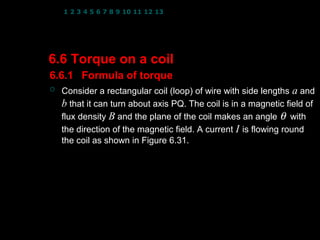
  • 1. 1 2 3 4 5 6 7 8 9 10 11 12 13 14 15 16 17 18 19 20 21 22 23 24 6.6 Torque on a coil 6.6.1 Formula of torque  Consider a rectangular coil (loop) of wire with side lengths a and b that it can turn about axis PQ. The coil is in a magnetic field of flux density B and the plane of the coil makes an angle θ with the direction of the magnetic field. A current I is flowing round the coil as shown in Figure 6.31. 1
  • 2. 1 2 3 4 5 6 7 8 9 10 11 12 13 14 15 16 17 18 19 20 21 22 23 24   B B  F1  F I  I P B A φ θ  b B  B   F1 a I Q F I Figure 6.31a 2
  • 3. 1 2 3 4 5 6 7 8 9 10 11 12 13 14 15 16 17 18 19 20 21 22 23 24  B    F1 B A θ φ b  sin φ rotation B 2 b φ rotation 2 Q b  sin φ F1 φ 2 Figure 6.31b: side view  From the Figure 6.31b, the magnitude of the force F1 is given by F1 = IlB sin 90 and l = a F1 = IaB  From the Figure 6.31a, the forces F lie along the axis PQ. 3
  • 4. 1 2 3 4 5 6 7 8 9 10 11 12 13 14 15 16 17 18 19 20 21 22 23 24  From the Figure 6.31a, the forces F lie along the axis PQ.  The resultant force on the coil is zero but the nett torque is not zero because the forces F1 are perpendicular to the axis PQ as shown in Figure 6.31a.  The forces F1 cause the coil to rotate in the clockwise direction about the axis PQ as shown in Figure 6.31b.  The magnitude of the nett torque about the axis PQ (refer to Figure 6.31b) is given by b  b  τ = − F1  sin φ  − F1  sin φ  2  2  b  and F = IaB = −2 F1  sin φ  1 2  b  = −2( IaB )  sin φ  2  = − IabB sin φ and ab = A(area of coil) 4
  • 5. 1 2 3 4 5 6 7 8 9 10 11 12 13 14 15 16 17 18 19 20 21 22 23 24 τ = IAB sin φ since φ = 90 − θ thus  ( τ = IAB sin 90 − θ ) τ = IAB cos θ  For a coil of N turns, the magnitude of the torque is given by τ = NIAB sin φ (6.14) OR τ = NIAB cos θ (6.15) where τ : torque on the coil B : magnetic flux density I : current flows in the coil   φ : angle between vector area A and B  θ : angle between the plane of the coil and B N : number of turns (coils) 5
  • 6. 1 2 3 4 5 6 7 8 9 10 11 12 13 14 15 16 17 18 19 20 21 22 23 24  From the eq. (6.14), thus the formula of torque in the vector form is given by  (   τ = NI A × B ) (6.16)  The torque is zero when θ = 90° or φ = 0° and is maximum when θ = 0°  φ = 90° as shown in Figures 6.32a and 6.32b. or  A  B B θ = 90 φ = 90  A φ =0  θ = 0 Figure 6.32a Figure 6.32b τ = NIAB sin 0  plane of the coil τ = NIAB sin 90 OR OR τ = NIAB cos 90 τ = NIAB cos 0 τ =0 τ max = NIAB 6
  • 7. 1 2 3 4 5 6 7 8 9 10 11 12 13 14 15 16 17 18 19 20 21 22 23 24  In a radial field, the plane of the coil is always parallel to the field magnetic field for any orientation of the coil about the vertical axis as shown in Figure 6.33. θ = 0 N S OR φ = 90  radial field fixed soft coil iron cylinder Figure 6.33: Plan view of moving coil meter Hence the torque on the coil in a radial field is always constant and maximum given by τ = NIAB sin 90 OR τ = NIAB cos 0 τ = NIAB maximum Radial field is used in moving coil galvanometer. 7
  • 8. 1 2 3 4 5 6 7 8 9 10 11 12 13 14 15 16 17 18 19 20 21 22 23 24 Example 13 : A 50 turns rectangular coil with sides 10 cm × 20 cm is placed vertically in a uniform horizontal magnetic field of magnitude 2.5 T. If the current flows in the coil is 7.3 A, determine the torque acting on the coil when the plane of the coil is a. perpendicular to the field, b. parallel to the field, c. at 75° to the field. Solution : N = 50 turns; B = 2.5 T; I = 7.3 A The area of the coil is given by A = (10 × 10 −2 )( 20 × 10 −2 ) = 2.0 × 10 −2 m 2 a.  B  From the figure, θ = 90° and φ = 0° , thus the θ = 90 torque on the coil is  A τ = NIAB cos θ OR τ = NIAB sin φ = NIAB cos 90  = NIAB sin 0 τ =0 8
  • 9. 1 2 3 4 5 6 7 8 9 10 11 12 13 14 15 16 17 18 19 20 21 22 23 24 Solution : N = 50 turns; B = 2.5 T; I = 7.3 A  b. A  From the figure, θ = 0° and φ = 90° , thus the B torque on the coil is φ = 90 τ = NIAB cos θ ( = ( 50 )( 7.3) 2.0 ×10 −2 )( 2.5) cos 0  τ = 18.3 N m  c. B From the figure, θ = 75° and φ = 15°,thus the torque on the coil is θ = 75  φ = 15 τ = NIAB cos θ  = ( 50 )( 7.3) ( 2.0 ×10 −2 )( 2.5) cos 75 A τ = 4.72 N m 9
  • 10. 1 2 3 4 5 6 7 8 9 10 11 12 13 14 15 16 17 18 19 20 21 22 23 24 6.6.2 Moving-coil galvanometer  A galvanometer consists of a coil of wire suspended in the magnetic field of a permanent magnet. The coil is rectangular shape and consists of many turns of fine wire as shown in Figure 6.34. 10 Figure 6.34
  • 11. 1 2 3 4 5 6 7 8 9 10 11 12 13 14 15 16 17 18 19 20 21 22 23 24  When the current I flows through the coil, the magnetic field coil exerts a torque on the coil as given by τ = NIAB  This torque is opposed by a spring which exerts a torque, τs given by τ s = kθ (6.17) where k : torsional constant θ : rotation angle of the coil in radian  The coil and pointer will rotate only to the point where the spring torque balances the torque due to magnetic field, field thus τ = τs NIAB = kθ kθ I= (6.18) NAB 11
  • 12. 1 2 3 4 5 6 7 8 9 10 11 12 13 14 15 16 17 18 19 20 21 22 23 24 Example 14 : A rectangular coil of 10 cm × 4.0 cm in a galvanometer has 50 turns and a magnetic flux density of 5.0 × 10⁻² T. The resistance of the coil is 40 Ω and a potential difference of 12 V is applied across the galvanometer, calculate the maximum torque on the coil. −2 Solution : N = 50 turns; B = 5.0 × 10 T; R = 40 Ω; V = 12 V The area of the coil is given by A = (10 × 10 −2 )( 4.0 × 10 −2 ) = 4.0 × 10 −3 m 2 The current through the galvanometer is V = IR 12 = I ( 40 ) I = 0.3 A Therefore the maximum torque on the coil is τ max = NIAB = ( 50)( 0.3) ( 4.0 ×10 −3 )( 5.0 ×10 −2 ) τ max = 3.0 × 10 −3 N m 12
  • 13. 1 2 3 4 5 6 7 8 9 10 11 12 13 14 15 16 17 18 19 20 21 22 23 24 6.6.3 Electrical instruments Ohmmeter  It is used to measure the unknown resistance of the resistor. resistor  Figure 6.35 shows the internal connection of an Ohmmeter. where ∞ 0 RM : meter (coil) resistance RS : variable resistance Ω RX : unknown resistance ε RM RS P RX Q Figure 6.35 13
  • 14. 1 2 3 4 5 6 7 8 9 10 11 12 13 14 15 16 17 18 19 20 21 22 23 24  When nothing is connected to terminals P and Q, so that the Q circuit is open (that is, when R → ∞ ), there is no current and no deflection. deflection  When terminals P and Q are short circuited (that is when R = 0), the ohmmeter deflects full-scale. 0 full-scale  For any value of RX the meter deflection depends on the value of RX. Ammeter  It is used to measure a current flows in the circuit. circuit  Ammeter is connected in series with other elements in the circuit because the current to be measured must pass directly through the ammeter. ammeter  An ammeter should have low internal resistance (RM) so that the current in the circuit would not affected. affected 14
  • 15. 1 2 3 4 5 6 7 8 9 10 11 12 13 14 15 16 17 18 19 20 21 22 23 24  The maximum reading from the ammeter is known as full scale deflection (fs).  If the full scale current passing through the ammeter then the potential difference (p.d.) across that ammeter is given by Vfs = I fs RM where RM : meter(coil) resistance I fs : full scale current Vfs : full scale potential difference (p.d.)  If the meter is used to measure currents that are larger than its full scale deflection (I >Ifs), some modification has to be done.  A resistor has to be connected in parallel with the meter (coil) resistance RM so that some of the current will bypasses the meter (coil) resistance. resistance  This parallel resistor is called a shunt denoted as RS.  Figure 6.36 shows the internal connection of an ammeter with a shunt in parallel. 15
  • 16. 1 2 3 4 5 6 7 8 9 10 11 12 13 14 15 16 17 18 19 20 21 22 23 24 0 max A I I fs I IS RM RS Figure 6.36  Since shunt is connected in parallel with the meter (coil) resistance then VRM = VRS I fs RM = I S RS and I S = I − I fs  I fs  I fs RM = ( I − I fs ) RS RS =  I −I   RM (6.19)  16 fs 
  • 17. 1 2 3 4 5 6 7 8 9 10 11 12 13 14 15 16 17 18 19 20 21 22 23 24 Voltmeter  It is used to measure a potential difference (p.d.) across electrical elements in the circuit. circuit  Voltmeter is connected in parallel with other elements in the circuit therefore its resistance must be larger than the resistance of the element so that a very small amount of current only can flows through it. An ideal voltmeter has it infinity resistance so that no current exist in it.  To measure a potential difference that are larger than its full scale deflection (V > Vfs), the voltmeter has to be modified.  A resistor has to be connected in series with the meter (coil) resistance RM so that only a fraction of the total p.d. appears across the RM and the remainder appears across the serial resistor.  This serial resistor is called a multiplier OR bobbin denoted as RB. 17
  • 18. 1 2 3 4 5 6 7 8 9 10 11 12 13 14 15 16 17 18 19 20 21 22 23 24  Figure 6.37 shows the internal connection of a voltmeter with a multiplier in series. 0 max V I fs RB RM V I I1 Electrical element  Since the multiplier is connected in series with the meter (coil) resistance Figure 6.37 then the current through them are the same, Ifs. 18
  • 19. 1 2 3 4 5 6 7 8 9 10 11 12 13 14 15 16 17 18 19 20 21 22 23 24  The p.d. across the electrical element is given by V = VRB + VRM Hence the multiplier resistance is V = I fs RB + I fs RM  V − I fs RM  RB =     (6.20)  I fs  Note:  To convert a galvanometer to ammeter, a shunt ammeter (parallel resistor) is used.  To convert a galvanometer to voltmeter, a multiplier voltmeter (serial resistor) is used. 19
  • 20. 1 2 3 4 5 6 7 8 9 10 11 12 13 14 15 16 17 18 19 20 21 22 23 24 Example 15 : A milliammeter with a full scale deflection of 20 mA and an internal resistance of 40 Ω is to be used as an ammeter with a full scale deflection of 500 mA. Calculate the resistance of the shunt required. I = 20 × 10 −3 A; R = 40 Ω; I = 500 × 10 −3 A fs M Solution : By applying the formula of shunt  resistor, thus I fs RS =   I − I  RM  fs   20 × 10 −3  = ( 40)  500 × 10 − 20 × 10 −3 −3    RS = 1.67 Ω 20
  • 21. 1 2 3 4 5 6 7 8 9 10 11 12 13 14 15 16 17 18 19 20 21 22 23 24 Example 16 : A galvanometer has an internal resistance of 30 Ω and deflects full scale for a 50 µA current. Describe how to use this galvanometer to make a. an ammeter to read currents up to 30 A. b. a voltmeter to give a full scale deflection of 1000 V. −6 Solution : I fs = 50 × 10 A; RM = 30 Ω a. We make an ammeter by putting a resistor in parallel ( RS) with the internal resistance, RM of the galvanometer as shown in figure below. RM I I fs IS G RS 21
  • 22. 1 2 3 4 5 6 7 8 9 10 11 12 13 14 15 16 17 18 19 20 21 22 23 24 Solution : I fs = 50 × 10 −6 A; RM = 30 Ω a. Given I = 30 A Since RS in parallel with RM therefore VRM = VRS I fs RM = I S RS and I S = I − I fs I fs RM = ( I − I fs ) RS (50 ×10 )( 30) = (30 − 50 ×10 ) R −6 −6 S RS = 5.0 × 10 −5 Ω in parallel. b. We make a voltmeter by putting a resistor in series (RB) with the internal resistance, RM of the galvanometer as shown in figure R RB M below. I fs G I fs V 22
  • 23. 1 2 3 4 5 6 7 8 9 10 11 12 13 14 15 16 17 18 19 20 21 22 23 24 −6 Solution : I fs = 50 × 10 A; RM = 30 Ω b. Given V = 1000 V Since RB in series with RM therefore V = VRB + VRM V = I fs RB + I fs RM ( ) ( 1000 = 50 × 10 −6 RB + 50 × 10 −6 ( 30 ) ) RB = 2.0 × 10 7 Ω in series. 23
  • 24. 1 2 3 4 5 6 7 8 9 10 11 12 13 14 15 16 17 18 19 20 21 22 23 24 Exercise 6.5 : 1. A moving coil meter has a 50 turns coil measuring 1.0 cm by 2.0 cm. It is held in a radial magnetic field of flux density 0.15 T and its suspension has a torsional constant of 3.0×10⁻⁶ N m rad−1. Determine the current is required to give a deflection of 0.5 rad. ANS. : 1.0× 10− 3 A 2. A milliammeter of negligible resistance produces a full scale deflection when the current is 1 mA. How would you convert the milliammeter to a voltmeter with full scale deflection of 10 V? ANS. : 1.0× 10⁴ Ω in series 3. A moving-coil meter has a resistance of 5.0 Ω and full scale deflection is produced by a current of 1.0 mA. How can this meter be adapted for use as : a. a voltmeter reading up to 10 V, b. a ammeter reading up to 2? ANS. : 9995 Ω in series; 2.5× 10− 3 Ω in parallel 24