SlideShare ist ein Scribd-Unternehmen logo
1 von 112
Downloaden Sie, um offline zu lesen
Area Velocity Sensor
HYB-UM-03155-EN-03 (March 2021) User Manual
IS-6000 Doppler
Stationary area velocity flow meter for partially filled pipes or
pressurized pipes and open channels
CONTENTS
1.	 General information . . . . . . . . . . . . . . . . . . . . . . . . . . . . . . . . . . . . . . . . . . . . . . . . . . . . . . . . . . . . . . . . . vii
1.1.	Copyright  .  .  .  .  .  .  .  .  .  .  .  .  .  .  .  .  .  .  .  .  .  .  .  .  .  .  .  .  .  .  .  .  .  .  .  .  .  .  .  .  .  .  .  .  .  .  .  .  .  .  .  .  .  .  .  .  .  .  .  .  .  .  .  .  .  .  .  . vii
1.2.	 Data Protection and Security  .  .  .  .  .  .  .  .  .  .  .  .  .  .  .  .  .  .  .  .  .  .  .  .  .  .  .  .  .  .  .  .  .  .  .  .  .  .  .  .  .  .  .  .  .  .  .  .  .  .  .  .  .  .  .  vii
1.3.	Liability .  .  .  .  .  .  .  .  .  .  .  .  .  .  .  .  .  .  .  .  .  .  .  .  .  .  .  .  .  .  .  .  .  .  .  .  .  .  .  .  .  .  .  .  .  .  .  .  .  .  .  .  .  .  .  .  .  .  .  .  .  .  .  .  .  .  .  .  .  vii
1.4.	 EU Conformity Declaration  .  .  .  .  .  .  .  .  .  .  .  .  .  .  .  .  .  .  .  .  .  .  .  .  .  .  .  .  .  .  .  .  .  .  .  .  .  .  .  .  .  .  .  .  .  .  .  .  .  .  .  .  .  .  .  .  . vii
1.5.	 Warnings and Safety Symbols  .  .  .  .  .  .  .  .  .  .  .  .  .  .  .  .  .  .  .  .  .  .  .  .  .  .  .  .  .  .  .  .  .  .  .  .  .  .  .  .  .  .  .  .  .  .  .  .  .  .  .  .  .  .  . vii
2.	 General Safety Instructions  .  .  .  .  .  .  .  .  .  .  .  .  .  .  .  .  .  .  .  .  .  .  .  .  .  .  .  .  .  .  .  .  .  .  .  .  .  .  .  .  .  .  .  .  .  .  .  .  .  .  .  .  .  .  .  .  .  .  .  .  .  8
2.1.	 Requirements for Personnel .  .  .  .  .  .  .  .  .  .  .  .  .  .  .  .  .  .  .  .  .  .  .  .  .  .  .  .  .  .  .  .  .  .  .  .  .  .  .  .  .  .  .  .  .  .  .  .  .  .  .  .  .  .  .  .  .  8
2.2.	 Intended Use .  .  .  .  .  .  .  .  .  .  .  .  .  .  .  .  .  .  .  .  .  .  .  .  .  .  .  .  .  .  .  .  .  .  .  .  .  .  .  .  .  .  .  .  .  .  .  .  .  .  .  .  .  .  .  .  .  .  .  .  .  .  .  .  .  . 8
2.3.	 Workplace Safety .  .  .  .  .  .  .  .  .  .  .  .  .  .  .  .  .  .  .  .  .  .  .  .  .  .  .  .  .  .  .  .  .  .  .  .  .  .  .  .  .  .  .  .  .  .  .  .  .  .  .  .  .  .  .  .  .  .  .  .  .  .  .  .  8
2.4.	 Operational Safety .  .  .  .  .  .  .  .  .  .  .  .  .  .  .  .  .  .  .  .  .  .  .  .  .  .  .  .  .  .  .  .  .  .  .  .  .  .  .  .  .  .  .  .  .  .  .  .  .  .  .  .  .  .  .  .  .  .  .  .  .  .  .  9
2.5.	 Product Safety .  .  .  .  .  .  .  .  .  .  .  .  .  .  .  .  .  .  .  .  .  .  .  .  .  .  .  .  .  .  .  .  .  .  .  .  .  .  .  .  .  .  .  .  .  .  .  .  .  .  .  .  .  .  .  .  .  .  .  .  .  .  .  .  . 9
2.6.	 Elecrtrical Safety  .  .  .  .  .  .  .  .  .  .  .  .  .  .  .  .  .  .  .  .  .  .  .  .  .  .  .  .  .  .  .  .  .  .  .  .  .  .  .  .  .  .  .  .  .  .  .  .  .  .  .  .  .  .  .  .  .  .  .  .  .  .  .  .  9
3.	 Product Description .  .  .  .  .  .  .  .  .  .  .  .  .  .  .  .  .  .  .  .  .  .  .  .  .  .  .  .  .  .  .  .  .  .  .  .  .  .  .  .  .  .  .  .  .  .  .  .  .  .  .  .  .  .  .  .  .  .  .  .  .  .  .  .  .  10
3.1.	 Scope of Delivery . . . . . . . . . . . . . . . . . . . . . . . . . . . . . . . . . . . . . . . . . . . . . . . . . . . . . . . . . . . . . . . 11
3.2.	Storage .  .  .  .  .  .  .  .  .  .  .  .  .  .  .  .  .  .  .  .  .  .  .  .  .  .  .  .  .  .  .  .  .  .  .  .  .  .  .  .  .  .  .  .  .  .  .  .  .  .  .  .  .  .  .  .  .  .  .  .  .  .  .  .  .  .  .  .  .  11
3.3.	Nameplate .  .  .  .  .  .  .  .  .  .  .  .  .  .  .  .  .  .  .  .  .  .  .  .  .  .  .  .  .  .  .  .  .  .  .  .  .  .  .  .  .  .  .  .  .  .  .  .  .  .  .  .  .  .  .  .  .  .  .  .  .  .  .  .  .  .  .  11
3.4.	 Measuring System .  .  .  .  .  .  .  .  .  .  .  .  .  .  .  .  .  .  .  .  .  .  .  .  .  .  .  .  .  .  .  .  .  .  .  .  .  .  .  .  .  .  .  .  .  .  .  .  .  .  .  .  .  .  .  .  .  .  .  .  .  .  11
3.4.1.	Transmitter  .  .  .  .  .  .  .  .  .  .  .  .  .  .  .  .  .  .  .  .  .  .  .  .  .  .  .  .  .  .  .  .  .  .  .  .  .  .  .  .  .  .  .  .  .  .  .  .  .  .  .  .  .  .  .  .  .  .  .  .  .  . 11
3.4.2.	Software  .  .  .  .  .  .  .  .  .  .  .  .  .  .  .  .  .  .  .  .  .  .  .  .  .  .  .  .  .  .  .  .  .  .  .  .  .  .  .  .  .  .  .  .  .  .  .  .  .  .  .  .  .  .  .  .  .  .  .  .  .  .  .  . 13
3.4.2.1.	System requirements .  .  .  .  .  .  .  .  .  .  .  .  .  .  .  .  .  .  .  .  .  .  .  .  .  .  .  .  .  .  .  .  .  .  .  .  .  .  .  .  .  .  .  .  .  .  .  .  .  .  . 13
3.4.3.	Sensors  .  .  .  .  .  .  .  .  .  .  .  .  .  .  .  .  .  .  .  .  .  .  .  .  .  .  .  .  .  .  .  .  .  .  .  .  .  .  .  .  .  .  .  .  .  .  .  .  .  .  .  .  .  .  .  .  .  .  .  .  .  .  .  .  . 14
3.4.3.1.	Area Velocity Sensors  .  .  .  .  .  .  .  .  .  .  .  .  .  .  .  .  .  .  .  .  .  .  .  .  .  .  .  .  .  .  .  .  .  .  .  .  .  .  .  .  .  .  .  .  .  .  .  .  .  . 14
3.4.4.	 Sensor Mounting Systems  .  .  .  .  .  .  .  .  .  .  .  .  .  .  .  .  .  .  .  .  .  .  .  .  .  .  .  .  .  .  .  .  .  .  .  .  .  .  .  .  .  .  .  .  .  .  .  .  .  .  .  .  . 15
4.	Installation  .  .  .  .  .  .  .  .  .  .  .  .  .  .  .  .  .  .  .  .  .  .  .  .  .  .  .  .  .  .  .  .  .  .  .  .  .  .  .  .  .  .  .  .  .  .  .  .  .  .  .  .  .  .  .  .  .  .  .  .  .  .  .  .  .  .  .  .  .  .  . 16
4.1.	 Installation Location .  .  .  .  .  .  .  .  .  .  .  .  .  .  .  .  .  .  .  .  .  .  .  .  .  .  .  .  .  .  .  .  .  .  .  .  .  .  .  .  .  .  .  .  .  .  .  .  .  .  .  .  .  .  .  .  .  .  .  .  .  16
4.2.	 Mounting the Transmitter  .  .  .  .  .  .  .  .  .  .  .  .  .  .  .  .  .  .  .  .  .  .  .  .  .  .  .  .  .  .  .  .  .  .  .  .  .  .  .  .  .  .  .  .  .  .  .  .  .  .  .  .  .  .  .  .  .  16
4.3.	 Mounting the Sensors  .  .  .  .  .  .  .  .  .  .  .  .  .  .  .  .  .  .  .  .  .  .  .  .  .  .  .  .  .  .  .  .  .  .  .  .  .  .  .  .  .  .  .  .  .  .  .  .  .  .  .  .  .  .  .  .  .  .  .  . 17
4.3.1.	 Installating an Area Velocity Sensor  .  .  .  .  .  .  .  .  .  .  .  .  .  .  .  .  .  .  .  .  .  .  .  .  .  .  .  .  .  .  .  .  .  .  .  .  .  .  .  .  .  .  .  .  .  .  . 17
4.4.	Calibration .  .  .  .  .  .  .  .  .  .  .  .  .  .  .  .  .  .  .  .  .  .  .  .  .  .  .  .  .  .  .  .  .  .  .  .  .  .  .  .  .  .  .  .  .  .  .  .  .  .  .  .  .  .  .  .  .  .  .  .  .  .  .  .  .  .  .  17
5.	 Electrical Connection  .  .  .  .  .  .  .  .  .  .  .  .  .  .  .  .  .  .  .  .  .  .  .  .  .  .  .  .  .  .  .  .  .  .  .  .  .  .  .  .  .  .  .  .  .  .  .  .  .  .  .  .  .  .  .  .  .  .  .  .  .  .  .  .  18
5.1.	 Terminal Compartment .  .  .  .  .  .  .  .  .  .  .  .  .  .  .  .  .  .  .  .  .  .  .  .  .  .  .  .  .  .  .  .  .  .  .  .  .  .  .  .  .  .  .  .  .  .  .  .  .  .  .  .  .  .  .  .  .  .  .  18
5.1.1.	 Pin Assignments  .  .  .  .  .  .  .  .  .  .  .  .  .  .  .  .  .  .  .  .  .  .  .  .  .  .  .  .  .  .  .  .  .  .  .  .  .  .  .  .  .  .  .  .  .  .  .  .  .  .  .  .  .  .  .  .  .  .  . 20
5.2.	 Connecting the Sensors .  .  .  .  .  .  .  .  .  .  .  .  .  .  .  .  .  .  .  .  .  .  .  .  .  .  .  .  .  .  .  .  .  .  .  .  .  .  .  .  .  .  .  .  .  .  .  .  .  .  .  .  .  .  .  .  .  .  . 22
Ultrasonic Flow Meters, IS-6000 Doppler
Page ii March 2021
HYB-UM-03155-EN-03
User Manual
5.2.1.	 Connecting Area Velocity Sensor  .  .  .  .  .  .  .  .  .  .  .  .  .  .  .  .  .  .  .  .  .  .  .  .  .  .  .  .  .  .  .  .  .  .  .  .  .  .  .  .  .  .  .  .  .  .  .  . 23
5.2.1.1.	Connecting Multiple Area Velocity Sensors  .  .  .  .  .  .  .  .  .  .  .  .  .  .  .  .  .  .  .  .  .  .  .  .  .  .  .  .  .  .  .  .  .  .  .  .  . 23
5.2.2.	 RS-485 /RS-232 Modbus Configuration .  .  .  .  .  .  .  .  .  .  .  .  .  .  .  .  .  .  .  .  .  .  .  .  .  .  .  .  .  .  .  .  .  .  .  .  .  .  .  .  .  .  .  .  . 23
5.3.	 Final Check of Electrical Connections .  .  .  .  .  .  .  .  .  .  .  .  .  .  .  .  .  .  .  .  .  .  .  .  .  .  .  .  .  .  .  .  .  .  .  .  .  .  .  .  .  .  .  .  .  .  .  .  .  .  24
6.	 Communication with Transmitter .  .  .  .  .  .  .  .  .  .  .  .  .  .  .  .  .  .  .  .  .  .  .  .  .  .  .  .  .  .  .  .  .  .  .  .  .  .  .  .  .  .  .  .  .  .  .  .  .  .  .  .  .  .  .  .  . 25
6.1.	 Control Panel and LC-Display .  .  .  .  .  .  .  .  .  .  .  .  .  .  .  .  .  .  .  .  .  .  .  .  .  .  .  .  .  .  .  .  .  .  .  .  .  .  .  .  .  .  .  .  .  .  .  .  .  .  .  .  .  .  .  25
6.2.	 Wireless Communication WiFi .  .  .  .  .  .  .  .  .  .  .  .  .  .  .  .  .  .  .  .  .  .  .  .  .  .  .  .  .  .  .  .  .  .  .  .  .  .  .  .  .  .  .  .  .  .  .  .  .  .  .  .  .  .  .  26
6.3.	 Communication to the Transmitter via Ethernet LAN .  .  .  .  .  .  .  .  .  .  .  .  .  .  .  .  .  .  .  .  .  .  .  .  .  .  .  .  .  .  .  .  .  .  .  .  .  .  .  .  27
7.	Programming  .  .  .  .  .  .  .  .  .  .  .  .  .  .  .  .  .  .  .  .  .  .  .  .  .  .  .  .  .  .  .  .  .  .  .  .  .  .  .  .  .  .  .  .  .  .  .  .  .  .  .  .  .  .  .  .  .  .  .  .  .  .  .  .  .  .  .  .  .  28
7.1.	Login .  .  .  .  .  .  .  .  .  .  .  .  .  .  .  .  .  .  .  .  .  .  .  .  .  .  .  .  .  .  .  .  .  .  .  .  .  .  .  .  .  .  .  .  .  .  .  .  .  .  .  .  .  .  .  .  .  .  .  .  .  .  .  .  .  .  .  .  .  .  . 28
7.1.1.	 User Groups and Access Rights .  .  .  .  .  .  .  .  .  .  .  .  .  .  .  .  .  .  .  .  .  .  .  .  .  .  .  .  .  .  .  .  .  .  .  .  .  .  .  .  .  .  .  .  .  .  .  .  .  . 29
7.2.	 Menu Structure .  .  .  .  .  .  .  .  .  .  .  .  .  .  .  .  .  .  .  .  .  .  .  .  .  .  .  .  .  .  .  .  .  .  .  .  .  .  .  .  .  .  .  .  .  .  .  .  .  .  .  .  .  .  .  .  .  .  .  .  .  .  .  .  30
7.2.1.	 Overview of Main Menu Items and Function of Corresponding Submenus  .  .  .  .  .  .  .  .  .  .  .  .  .  .  .  .  .  .  .  .  .  . 31
7.3.	 Settings for Language and Location .  .  .  .  .  .  .  .  .  .  .  .  .  .  .  .  .  .  .  .  .  .  .  .  .  .  .  .  .  .  .  .  .  .  .  .  .  .  .  .  .  .  .  .  .  .  .  .  .  .  .  32
7.4.	 Home - Overview .  .  .  .  .  .  .  .  .  .  .  .  .  .  .  .  .  .  .  .  .  .  .  .  .  .  .  .  .  .  .  .  .  .  .  .  .  .  .  .  .  .  .  .  .  .  .  .  .  .  .  .  .  .  .  .  .  .  .  .  .  .  .  33
7.5.	 Graph - Data Visualization .  .  .  .  .  .  .  .  .  .  .  .  .  .  .  .  .  .  .  .  .  .  .  .  .  .  .  .  .  .  .  .  .  .  .  .  .  .  .  .  .  .  .  .  .  .  .  .  .  .  .  .  .  .  .  .  .  34
7.5.1.	 Three-Day Display  .  .  .  .  .  .  .  .  .  .  .  .  .  .  .  .  .  .  .  .  .  .  .  .  .  .  .  .  .  .  .  .  .  .  .  .  .  .  .  .  .  .  .  .  .  .  .  .  .  .  .  .  .  .  .  .  .  . 34
7.5.2.	Current  .  .  .  .  .  .  .  .  .  .  .  .  .  .  .  .  .  .  .  .  .  .  .  .  .  .  .  .  .  .  .  .  .  .  .  .  .  .  .  .  .  .  .  .  .  .  .  .  .  .  .  .  .  .  .  .  .  .  .  .  .  .  .  .  . 35
7.5.3.	History   .  .  .  .  .  .  .  .  .  .  .  .  .  .  .  .  .  .  .  .  .  .  .  .  .  .  .  .  .  .  .  .  .  .  .  .  .  .  .  .  .  .  .  .  .  .  .  .  .  .  .  .  .  .  .  .  .  .  .  .  .  .  .  .  . 36
7.5.4.	 Velocity Profile   .  .  .  .  .  .  .  .  .  .  .  .  .  .  .  .  .  .  .  .  .  .  .  .  .  .  .  .  .  .  .  .  .  .  .  .  .  .  .  .  .  .  .  .  .  .  .  .  .  .  .  .  .  .  .  .  .  .  .  . 37
7.5.5.	Settings  .  .  .  .  .  .  .  .  .  .  .  .  .  .  .  .  .  .  .  .  .  .  .  .  .  .  .  .  .  .  .  .  .  .  .  .  .  .  .  .  .  .  .  .  .  .  .  .  .  .  .  .  .  .  .  .  .  .  .  .  .  .  .  . 38
7.6.	 Download, Data Transfer .  .  .  .  .  .  .  .  .  .  .  .  .  .  .  .  .  .  .  .  .  .  .  .  .  .  .  .  .  .  .  .  .  .  .  .  .  .  .  .  .  .  .  .  .  .  .  .  .  .  .  .  .  .  .  .  .  .  39
7.6.1.	Download  .  .  .  .  .  .  .  .  .  .  .  .  .  .  .  .  .  .  .  .  .  .  .  .  .  .  .  .  .  .  .  .  .  .  .  .  .  .  .  .  .  .  .  .  .  .  .  .  .  .  .  .  .  .  .  .  .  .  .  .  .  .  . 39
7.6.2.	Setting   .  .  .  .  .  .  .  .  .  .  .  .  .  .  .  .  .  .  .  .  .  .  .  .  .  .  .  .  .  .  .  .  .  .  .  .  .  .  .  .  .  .  .  .  .  .  .  .  .  .  .  .  .  .  .  .  .  .  .  .  .  .  .  .  . 41
7.7.	 Parameter - Parameterization .  .  .  .  .  .  .  .  .  .  .  .  .  .  .  .  .  .  .  .  .  .  .  .  .  .  .  .  .  .  .  .  .  .  .  .  .  .  .  .  .  .  .  .  .  .  .  .  .  .  .  .  .  .  .  41
7.7.1.	Geometry  .  .  .  .  .  .  .  .  .  .  .  .  .  .  .  .  .  .  .  .  .  .  .  .  .  .  .  .  .  .  .  .  .  .  .  .  .  .  .  .  .  .  .  .  .  .  .  .  .  .  .  .  .  .  .  .  .  .  .  .  .  .  . 42
7.7.1.1.	Sludge Level  .  .  .  .  .  .  .  .  .  .  .  .  .  .  .  .  .  .  .  .  .  .  .  .  .  .  .  .  .  .  .  .  .  .  .  .  .  .  .  .  .  .  .  .  .  .  .  .  .  .  .  .  .  .  .  . 47
7.7.2.	 Water Level  .  .  .  .  .  .  .  .  .  .  .  .  .  .  .  .  .  .  .  .  .  .  .  .  .  .  .  .  .  .  .  .  .  .  .  .  .  .  .  .  .  .  .  .  .  .  .  .  .  .  .  .  .  .  .  .  .  .  .  .  .  . 47
7.7.3.	 Measurement Range  .  .  .  .  .  .  .  .  .  .  .  .  .  .  .  .  .  .  .  .  .  .  .  .  .  .  .  .  .  .  .  .  .  .  .  .  .  .  .  .  .  .  .  .  .  .  .  .  .  .  .  .  .  .  .  . 51
7.7.4.	Calibration .  .  .  .  .  .  .  .  .  .  .  .  .  .  .  .  .  .  .  .  .  .  .  .  .  .  .  .  .  .  .  .  .  .  .  .  .  .  .  .  .  .  .  .  .  .  .  .  .  .  .  .  .  .  .  .  .  .  .  .  .  .  . 55
7.7.5.	Replacement  .  .  .  .  .  .  .  .  .  .  .  .  .  .  .  .  .  .  .  .  .  .  .  .  .  .  .  .  .  .  .  .  .  .  .  .  .  .  .  .  .  .  .  .  .  .  .  .  .  .  .  .  .  .  .  .  .  .  .  .  . 57
7.7.6.	Temperature  .  .  .  .  .  .  .  .  .  .  .  .  .  .  .  .  .  .  .  .  .  .  .  .  .  .  .  .  .  .  .  .  .  .  .  .  .  .  .  .  .  .  .  .  .  .  .  .  .  .  .  .  .  .  .  .  .  .  .  .  . 62
7.8.	 I/Os – Digital and analog inputs and outputs .  .  .  .  .  .  .  .  .  .  .  .  .  .  .  .  .  .  .  .  .  .  .  .  .  .  .  .  .  .  .  .  .  .  .  .  .  .  .  .  .  .  .  .  .  62
Page iii
March 2021 HYB-UM-03155-EN-03
Ultrasonic Flow Meters, IS-6000 Doppler
7.8.1.	 Analog Input  .  .  .  .  .  .  .  .  .  .  .  .  .  .  .  .  .  .  .  .  .  .  .  .  .  .  .  .  .  .  .  .  .  .  .  .  .  .  .  .  .  .  .  .  .  .  .  .  .  .  .  .  .  .  .  .  .  .  .  .  . 62
7.8.2.	 Analog Output  .  .  .  .  .  .  .  .  .  .  .  .  .  .  .  .  .  .  .  .  .  .  .  .  .  .  .  .  .  .  .  .  .  .  .  .  .  .  .  .  .  .  .  .  .  .  .  .  .  .  .  .  .  .  .  .  .  .  .  . 65
7.8.3.	 Digital Input  .  .  .  .  .  .  .  .  .  .  .  .  .  .  .  .  .  .  .  .  .  .  .  .  .  .  .  .  .  .  .  .  .  .  .  .  .  .  .  .  .  .  .  .  .  .  .  .  .  .  .  .  .  .  .  .  .  .  .  .  . 66
7.8.4.	 Digital Output  .  .  .  .  .  .  .  .  .  .  .  .  .  .  .  .  .  .  .  .  .  .  .  .  .  .  .  .  .  .  .  .  .  .  .  .  .  .  .  .  .  .  .  .  .  .  .  .  .  .  .  .  .  .  .  .  .  .  .  . 66
7.8.5.	 Users Values  .  .  .  .  .  .  .  .  .  .  .  .  .  .  .  .  .  .  .  .  .  .  .  .  .  .  .  .  .  .  .  .  .  .  .  .  .  .  .  .  .  .  .  .  .  .  .  .  .  .  .  .  .  .  .  .  .  .  .  .  .  . 70
7.9.	 Settings – Data Logging and Display .  .  .  .  .  .  .  .  .  .  .  .  .  .  .  .  .  .  .  .  .  .  .  .  .  .  .  .  .  .  .  .  .  .  .  .  .  .  .  .  .  .  .  .  .  .  .  .  .  .  . 70
7.9.1.	Logging  .  .  .  .  .  .  .  .  .  .  .  .  .  .  .  .  .  .  .  .  .  .  .  .  .  .  .  .  .  .  .  .  .  .  .  .  .  .  .  .  .  .  .  .  .  .  .  .  .  .  .  .  .  .  .  .  .  .  .  .  .  .  .  . 71
7.9.2.	Units  .  .  .  .  .  .  .  .  .  .  .  .  .  .  .  .  .  .  .  .  .  .  .  .  .  .  .  .  .  .  .  .  .  .  .  .  .  .  .  .  .  .  .  .  .  .  .  .  .  .  .  .  .  .  .  .  .  .  .  .  .  .  .  .  .  . 72
7.9.3.	 Displayed Units .  .  .  .  .  .  .  .  .  .  .  .  .  .  .  .  .  .  .  .  .  .  .  .  .  .  .  .  .  .  .  .  .  .  .  .  .  .  .  .  .  .  .  .  .  .  .  .  .  .  .  .  .  .  .  .  .  .  .  . 74
7.9.4.	Totalizer  .  .  .  .  .  .  .  .  .  .  .  .  .  .  .  .  .  .  .  .  .  .  .  .  .  .  .  .  .  .  .  .  .  .  .  .  .  .  .  .  .  .  .  .  .  .  .  .  .  .  .  .  .  .  .  .  .  .  .  .  .  .  .  . 75
7.10.	Communication – Network Settings . . . . . . . . . . . . . . . . . . . . . . . . . . . . . . . . . . . . . . . . . . . . . . . . . . . 76
7.10.1.	Network  .  .  .  .  .  .  .  .  .  .  .  .  .  .  .  .  .  .  .  .  .  .  .  .  .  .  .  .  .  .  .  .  .  .  .  .  .  .  .  .  .  .  .  .  .  .  .  .  .  .  .  .  .  .  .  .  .  .  .  .  .  .  .  . 77
7.10.1.1 Manual Input and Changing the IP Address   .  .  .  .  .  .  .  .  .  .  .  .  .  .  .  .  .  .  .  .  .  .  .  .  .  .  .  .  .  .  .  .  .  .  .  . 78
7.10.2.	SMS  .  .  .  .  .  .  .  .  .  .  .  .  .  .  .  .  .  .  .  .  .  .  .  .  .  .  .  .  .  .  .  .  .  .  .  .  .  .  .  .  .  .  .  .  .  .  .  .  .  .  .  .  .  .  .  .  .  .  .  .  .  .  .  .  .  .  . 85
7.10.3.	FTP  .  .  .  .  .  .  .  .  .  .  .  .  .  .  .  .  .  .  .  .  .  .  .  .  .  .  .  .  .  .  .  .  .  .  .  .  .  .  .  .  .  .  .  .  .  .  .  .  .  .  .  .  .  .  .  .  .  .  .  .  .  .  .  .  .  .  . 86
7.10.4.	Modbus  .  .  .  .  .  .  .  .  .  .  .  .  .  .  .  .  .  .  .  .  .  .  .  .  .  .  .  .  .  .  .  .  .  .  .  .  .  .  .  .  .  .  .  .  .  .  .  .  .  .  .  .  .  .  .  .  .  .  .  .  .  .  .  . 87
7.10.5.	Serial  .  .  .  .  .  .  .  .  .  .  .  .  .  .  .  .  .  .  .  .  .  .  .  .  .  .  .  .  .  .  .  .  .  .  .  .  .  .  .  .  .  .  .  .  .  .  .  .  .  .  .  .  .  .  .  .  .  .  .  .  .  .  .  .  .  . 89
7.11.	Diagnosis .  .  .  .  .  .  .  .  .  .  .  .  .  .  .  .  .  .  .  .  .  .  .  .  .  .  .  .  .  .  .  .  .  .  .  .  .  .  .  .  .  .  .  .  .  .  .  .  .  .  .  .  .  .  .  .  .  .  .  .  .  .  .  .  .  .  .  .  91
7.11.1.	 Log Files  .  .  .  .  .  .  .  .  .  .  .  .  .  .  .  .  .  .  .  .  .  .  .  .  .  .  .  .  .  .  .  .  .  .  .  .  .  .  .  .  .  .  .  .  .  .  .  .  .  .  .  .  .  .  .  .  .  .  .  .  .  .  .  . 91
7.11.2.	Data  .  .  .  .  .  .  .  .  .  .  .  .  .  .  .  .  .  .  .  .  .  .  .  .  .  .  .  .  .  .  .  .  .  .  .  .  .  .  .  .  .  .  .  .  .  .  .  .  .  .  .  .  .  .  .  .  .  .  .  .  .  .  .  .  .  .  . 92
7.12.	Extras .  .  .  .  .  .  .  .  .  .  .  .  .  .  .  .  .  .  .  .  .  .  .  .  .  .  .  .  .  .  .  .  .  .  .  .  .  .  .  .  .  .  .  .  .  .  .  .  .  .  .  .  .  .  .  .  .  .  .  .  .  .  .  .  .  .  .  .  .  .  92
7.12.1.	 Language and Location  .  .  .  .  .  .  .  .  .  .  .  .  .  .  .  .  .  .  .  .  .  .  .  .  .  .  .  .  .  .  .  .  .  .  .  .  .  .  .  .  .  .  .  .  .  .  .  .  .  .  .  .  .  . 93
7.12.2.	 Date Time  .  .  .  .  .  .  .  .  .  .  .  .  .  .  .  .  .  .  .  .  .  .  .  .  .  .  .  .  .  .  .  .  .  .  .  .  .  .  .  .  .  .  .  .  .  .  .  .  .  .  .  .  .  .  .  .  .  .  .  .  .  .  . 95
7.12.3.	 LC Display   .  .  .  .  .  .  .  .  .  .  .  .  .  .  .  .  .  .  .  .  .  .  .  .  .  .  .  .  .  .  .  .  .  .  .  .  .  .  .  .  .  .  .  .  .  .  .  .  .  .  .  .  .  .  .  .  .  .  .  .  .  .  . 96
7.12.4.	 Power Management .  .  .  .  .  .  .  .  .  .  .  .  .  .  .  .  .  .  .  .  .  .  .  .  .  .  .  .  .  .  .  .  .  .  .  .  .  .  .  .  .  .  .  .  .  .  .  .  .  .  .  .  .  .  .  .  . 97
7.12.5.	 Backup & Update .  .  .  .  .  .  .  .  .  .  .  .  .  .  .  .  .  .  .  .  .  .  .  .  .  .  .  .  .  .  .  .  .  .  .  .  .  .  .  .  .  .  .  .  .  .  .  .  .  .  .  .  .  .  .  .  .  .  . 98
7.13.	Abbreviations  .  .  .  .  .  .  .  .  .  .  .  .  .  .  .  .  .  .  .  .  .  .  .  .  .  .  .  .  .  .  .  .  .  .  .  .  .  .  .  .  .  .  .  .  .  .  .  .  .  .  .  .  .  .  .  .  .  .  .  .  .  .  .  . 100
8.	Service  .  .  .  .  .  .  .  .  .  .  .  .  .  .  .  .  .  .  .  .  .  .  .  .  .  .  .  .  .  .  .  .  .  .  .  .  .  .  .  .  .  .  .  .  .  .  .  .  .  .  .  .  .  .  .  .  .  .  .  .  .  .  .  .  .  .  .  .  .  .  .  .  101
8.1.	 Cleaning, Maintenance and Care .  .  .  .  .  .  .  .  .  .  .  .  .  .  .  .  .  .  .  .  .  .  .  .  .  .  .  .  .  .  .  .  .  .  .  .  .  .  .  .  .  .  .  .  .  .  .  .  .  .  .  .  101
8.2.	Troubleshooting  .  .  .  .  .  .  .  .  .  .  .  .  .  .  .  .  .  .  .  .  .  .  .  .  .  .  .  .  .  .  .  .  .  .  .  .  .  .  .  .  .  .  .  .  .  .  .  .  .  .  .  .  .  .  .  .  .  .  .  .  .  .  101
8.2.1.	 Error Codes  .  .  .  .  .  .  .  .  .  .  .  .  .  .  .  .  .  .  .  .  .  .  .  .  .  .  .  .  .  .  .  .  .  .  .  .  .  .  .  .  .  .  .  .  .  .  .  .  .  .  .  .  .  .  .  .  .  .  .  .  . 101
8.2.2.	 Reset to Factory Settings .  .  .  .  .  .  .  .  .  .  .  .  .  .  .  .  .  .  .  .  .  .  .  .  .  .  .  .  .  .  .  .  .  .  .  .  .  .  .  .  .  .  .  .  .  .  .  .  .  .  .  .  .  102
8.3.	 Return / Repair  .  .  .  .  .  .  .  .  .  .  .  .  .  .  .  .  .  .  .  .  .  .  .  .  .  .  .  .  .  .  .  .  .  .  .  .  .  .  .  .  .  .  .  .  .  .  .  .  .  .  .  .  .  .  .  .  .  .  .  .  .  .  .  104
8.4.	Disposal  .  .  .  .  .  .  .  .  .  .  .  .  .  .  .  .  .  .  .  .  .  .  .  .  .  .  .  .  .  .  .  .  .  .  .  .  .  .  .  .  .  .  .  .  .  .  .  .  .  .  .  .  .  .  .  .  .  .  .  .  .  .  .  .  .  .  .  . 104
9.	 Operating Principle .  .  .  .  .  .  .  .  .  .  .  .  .  .  .  .  .  .  .  .  .  .  .  .  .  .  .  .  .  .  .  .  .  .  .  .  .  .  .  .  .  .  .  .  .  .  .  .  .  .  .  .  .  .  .  .  .  .  .  .  .  .  .  .  . 105
9.1.	 Doppler Flow Meter .  .  .  .  .  .  .  .  .  .  .  .  .  .  .  .  .  .  .  .  .  .  .  .  .  .  .  .  .  .  .  .  .  .  .  .  .  .  .  .  .  .  .  .  .  .  .  .  .  .  .  .  .  .  .  .  .  .  .  .  105
9.2.	 Pulse Wave Doppler (PW) .  .  .  .  .  .  .  .  .  .  .  .  .  .  .  .  .  .  .  .  .  .  .  .  .  .  .  .  .  .  .  .  .  .  .  .  .  .  .  .  .  .  .  .  .  .  .  .  .  .  .  .  .  .  .  .  . 106
Page iv March 2021
HYB-UM-03155-EN-03
LIST OF TABLES
Table 1: Error codes (depending on the configuration of the measuring system) .  .  .  .  .  .  .  .  .  .  .  .  .  .  .  .  .  .  .  .  .  .  .  .  .  .  .  .  100
Table 2: Specific roughness coefficients (Manning & Strickler coefficients) for closed conduit, partly full metal pipesl .  .  .  .  . 109
Table 3: Specific roughness coefficients (Manning & Strickler coefficients) for closed conduit, partly full non-metal pipesl  .  110
Table 4: Specific roughness coefficients (Manning & Strickler coefficients) for lined or built-up metal channels .  .  .  .  .  .  .  .  . 110
Table 5: Specific roughness coefficients (Manning & Strickler coefficients) for lined or built-up non-metal channels .  .  .  .  .  . 111
Table 6: Specific roughness coefficients (Manning & Strickler coefficients) for excavated or dredged channels .  .  .  .  .  .  .  .  .  111
Table 7: Specific roughness coefficients (Manning & Strickler coefficients) for regular/irregular sections .  .  .  .  .  .  .  .  .  .  .  .  .  111
User Manual
9.3.	 Ultrasonic Signal Diagnostics .  .  .  .  .  .  .  .  .  .  .  .  .  .  .  .  .  .  .  .  .  .  .  .  .  .  .  .  .  .  .  .  .  .  .  .  .  .  .  .  .  .  .  .  .  .  .  .  .  .  .  .  .  .  106
10.	Technical Data .  .  .  .  .  .  .  .  .  .  .  .  .  .  .  .  .  .  .  .  .  .  .  .  .  .  .  .  .  .  .  .  .  .  .  .  .  .  .  .  .  .  .  .  .  .  .  .  .  .  .  .  .  .  .  .  .  .  .  .  .  .  .  .  .  .  .  .  107
10.1.	Transmitter  .  .  .  .  .  .  .  .  .  .  .  .  .  .  .  .  .  .  .  .  .  .  .  .  .  .  .  .  .  .  .  .  .  .  .  .  .  .  .  .  .  .  .  .  .  .  .  .  .  .  .  .  .  .  .  .  .  .  .  .  .  .  .  .  .  . 107
10.2.	 Area Velocity Sensor .  .  .  .  .  .  .  .  .  .  .  .  .  .  .  .  .  .  .  .  .  .  .  .  .  .  .  .  .  .  .  .  .  .  .  .  .  .  .  .  .  .  .  .  .  .  .  .  .  .  .  .  .  .  .  .  .  .  .  .  108
11.	Annex .  .  .  .  .  .  .  .  .  .  .  .  .  .  .  .  .  .  .  .  .  .  .  .  .  .  .  .  .  .  .  .  .  .  .  .  .  .  .  .  .  .  .  .  .  .  .  .  .  .  .  .  .  .  .  .  .  .  .  .  .  .  .  .  .  .  .  .  .  .  .  .  .  109
11.1.	Roughness Coefficients .  .  .  .  .  .  .  .  .  .  .  .  .  .  .  .  .  .  .  .  .  .  .  .  .  .  .  .  .  .  .  .  .  .  .  .  .  .  .  .  .  .  .  .  .  .  .  .  .  .  .  .  .  .  .  .  .  .  109
11.1.1.	 Closed conduit, Partly Full Metal Pipes  .  .  .  .  .  .  .  .  .  .  .  .  .  .  .  .  .  .  .  .  .  .  .  .  .  .  .  .  .  .  .  .  .  .  .  .  .  .  .  .  .  .  .  .  109
11.1.2.	 Closed Conduit, Partly Full Non-Metal Pipes  .  .  .  .  .  .  .  .  .  .  .  .  .  .  .  .  .  .  .  .  .  .  .  .  .  .  .  .  .  .  .  .  .  .  .  .  .  .  .  . 110
11.1.3.	 Lined or Built-Up Metal Channels  .  .  .  .  .  .  .  .  .  .  .  .  .  .  .  .  .  .  .  .  .  .  .  .  .  .  .  .  .  .  .  .  .  .  .  .  .  .  .  .  .  .  .  .  .  .  . 110
11.1.4.	 Lined or Built-Up Non-Metal Channels  .  .  .  .  .  .  .  .  .  .  .  .  .  .  .  .  .  .  .  .  .  .  .  .  .  .  .  .  .  .  .  .  .  .  .  .  .  .  .  .  .  .  .  .  111
11.1.5.	 Excavated or Dredged Channels  .  .  .  .  .  .  .  .  .  .  .  .  .  .  .  .  .  .  .  .  .  .  .  .  .  .  .  .  .  .  .  .  .  .  .  .  .  .  .  .  .  .  .  .  .  .  .  .  111
11.1.6.	 Natural Channels .  .  .  .  .  .  .  .  .  .  .  .  .  .  .  .  .  .  .  .  .  .  .  .  .  .  .  .  .  .  .  .  .  .  .  .  .  .  .  .  .  .  .  .  .  .  .  .  .  .  .  .  .  .  .  .  .  .  111
11.2.	Bibliography .  .  .  .  .  .  .  .  .  .  .  .  .  .  .  .  .  .  .  .  .  .  .  .  .  .  .  .  .  .  .  .  .  .  .  .  .  .  .  .  .  .  .  .  .  .  .  .  .  .  .  .  .  .  .  .  .  .  .  .  .  .  .  .  .  111
Page v
March 2021 HYB-UM-03155-EN-03
LIST OF FIGURES
Figure 1: Combined ultrasonic velocity and water level measurement with an area velocity sensor (combination sensor)  .  .  10
Figure 2: Nameplate (example) .  .  .  .  .  .  .  .  .  .  .  .  .  .  .  .  .  .  .  .  .  .  .  .  .  .  .  .  .  .  .  .  .  .  .  .  .  .  .  .  .  .  .  .  .  .  .  .  .  .  .  .  .  .  .  .  .  .  .  .  11
Figure 3: a),b) Front view of transmitter housing for wall installation, enclosure dimensions (in mm)
c),d) top view and side view, dimensions (in mm)
e) bottom view  .  .  .  .  .  .  .  .  .  .  .  .  .  .  .  .  .  .  .  .  .  .  .  .  .  .  .  .  .  .  .  .  .  .  .  .  .  .  .  .  .  .  .  .  .  .  .  .  .  .  .  .  .  .  .  .  .  .  .  .  .  .  .  .  .  .  .  .  .  .  . 12
Figure 4: a) Scheme for combined ultrasonic velocity (v) and water level (h) measurement
b) Area velocity sensor incl. mounting plate
c) Dimensions (length, depth in mm), top view
d) Dimensions (height in mm), side view  .  .  .  .  .  .  .  .  .  .  .  .  .  .  .  .  .  .  .  .  .  .  .  .  .  .  .  .  .  .  .  .  .  .  .  .  .  .  .  .  .  .  .  .  .  .  .  .  .  .  .  .  .  .  14
Figure 5: Example for sensor mounting system (tension ring) in a pipe .  .  .  .  .  .  .  .  .  .  .  .  .  .  .  .  .  .  .  .  .  .  .  .  .  .  .  .  .  .  .  .  .  .  .  15
Figure 6: Installation of sensors against flow direction (1) and in flow direction (2) .  .  .  .  .  .  .  .  .  .  .  .  .  .  .  .  .  .  .  .  .  .  .  .  .  .  .  . 17
Figure 7: Overview terminal compartment .  .  .  .  .  .  .  .  .  .  .  .  .  .  .  .  .  .  .  .  .  .  .  .  .  .  .  .  .  .  .  .  .  .  .  .  .  .  .  .  .  .  .  .  .  .  .  .  .  .  .  .  .  19
Figure 8: Overview pin assignment  .  .  .  .  .  .  .  .  .  .  .  .  .  .  .  .  .  .  .  .  .  .  .  .  .  .  .  .  .  .  .  .  .  .  .  .  .  .  .  .  .  .  .  .  .  .  .  .  .  .  .  .  .  .  .  .  .  20
Figure 9: Pin assignment (# 71-78) for the connection of area velocity sensor .  .  .  .  .  .  .  .  .  .  .  .  .  .  .  .  .  .  .  .  .  .  .  .  .  .  .  .  .  .  .  23
Figure 10: Pin assignments # 21-26 for connection on RS-485 2-wire / 4-wire and RS-232
(pin assignment for aluminium enclosure – integrated 4G/3G/2G modem) .  .  .  .  .  .  .  .  .  .  .  .  .  .  .  .  .  .  .  .  .  .  .  .  .  .  .  .  .  .  .  .  . 23
Figure 11: Control panel and display functions .  .  .  .  .  .  .  .  .  .  .  .  .  .  .  .  .  .  .  .  .  .  .  .  .  .  .  .  .  .  .  .  .  .  .  .  .  .  .  .  .  .  .  .  .  .  .  .  .  .  25
Figure 12: Height of sediment layer in a cross section (sludge level) .  .  .  .  .  .  .  .  .  .  .  .  .  .  .  .  .  .  .  .  .  .  .  .  .  .  .  .  .  .  .  .  .  .  .  .  .  47
Figure 13: Doppler Principle .  .  .  .  .  .  .  .  .  .  .  .  .  .  .  .  .  .  .  .  .  .  .  .  .  .  .  .  .  .  .  .  .  .  .  .  .  .  .  .  .  .  .  .  .  .  .  .  .  .  .  .  .  .  .  .  .  .  .  .  .  104
Ultrasonic Flow Meters, IS-6000 Doppler
Page vi March 2021
HYB-UM-03155-EN-03
1.	 GENERAL INFORMATION
This user manual provides all necessary information for the operation and the efficient and safe use of the IS-6000 Doppler
flow meter. It contains important information on product identification, storage, installation, commissioning, operation,
maintenance and disposal of the device. Before putting the device into operation, read this user manual carefully. To prevent
possible injuries to the user and damage, use the device only for the intended use described below. Always keep this
document handy in the vicinity of the device! If you do not understand the contents of this document, contact the
manufacturer. In no case may the manufacturer be held reliable for any damage or injury caused by misunderstanding
of the information.
1.1.	 Copyright
All rights reserved. The contents and works in this document are subject to German copyright. Contributions from third
parties are identified as such. No part of this documentation may be reproduced in any form, stored or transferred, neither
electronically, mechanically, photo-technically, by recording on data media or otherwise, as long as no expressly written
authorization from the publisher is present.
1.2.	 Data Protection and Security
All data should be backed-up prior to the installation of any peripheral storage device. The manufacturer will not be
responsible for any loss of data resulting from the use or misuse of this or any other product from the manufacturer. Data
security is given by personated login with username and password. Data will be saved on the server with appropriate security
measures for protection against data loss, data abuse and unauthorized data modifications.
There are inherent security risks in transmitting data via the internet. It is not possible to safeguard completely against
unauthorized access by third parties.
The use of contact data published within the framework of the imprint obligation by third parties for the transmission of not
expressly requested advertising and information material is hereby expressly rejected.
1.3.	 Liability
In case of inappropriate or unintended use, no liability for the proper function of the device can be assumed. Improper
installation and operation of the device will void the warranty. The manufacturer has made every effort to assure the accuracy
of the contents of this manual and the software. However, the manufacturer can offer no guarantee that the information
provided is accurate and/or free of error. The information provided in this manual is subject to change without notice at any
time. The manufacturer reserves the right to alter designs, layouts or software without prior notification and will not be liable
in any way for possible consequences of such changes.
1.4.	 EU Conformity Declaration
The manufacturer hereby declares that this product complies with Directive 2014/30/EU, 2014/35/EU, 014/53/EU, 2014/65/EU.
1.5.	 Warnings and Safety Symbols
Depending on the hazard level, warnings are displayed as follows.
Immediate danger. Indicates a potentially or imminently hazardous situation which, if not avoided, will
result in death or serious injury.
Medium risk. Indicates a potentially or imminently hazardous situation which, if not avoided, could result
in death or serious injury.
Minor risk. Indicates a potentially hazardous situation that may result in minor or moderate
injury or damage.
MPORTANT
I
Important handling instruction. Indicates a situation which, if not avoided, may cause damage to the device. Information that
requires special emphasis.
OTE:	
N This symbol indicates helpful notes and information for handling the device.
User Manual
Page vii
March 2021 HYB-UM-03155-EN-03
2.	 GENERAL SAFETY INSTRUCTIONS
2.1.	 Requirements for Personnel
Installation, electrical connections, commissioning, operation, and maintenance of the device must be carried out by
qualified, specially trained and authorized personnel.
Personal injuries and serious damage to the device are caused by insufficiently qualified personnel.
Qualified personnel:
•	 Are persons who, through their professional training and education, are familiar with the safety guidelines of electrical and
automation engineering.
•	 Are persons who, as project, commissioning, and installation personnel, are authorized to commission, ground and label
circuits and devices/systems in accordance with the standards of safety engineering.
•	 Must be able to safely assess the results of their work and must be familiar with the contents of these
operating instructions.
Special trained personnel:
•	 Are persons, for example fitters or electricians, who can perform various tasks such as transport, assembly and installation
of the product under the supervision of an authorized person. The persons must have experience in handling the product.
Authorized personnel:
•	 Are persons who are indented to work on the basis of legal regulations or have been approved by the manufacturer
for certain activities.
The following requirements must be met:
•	 The user manual must be read carefully and fully understood by qualified personnel. Instructions must be followed.
•	 Qualified personnel must be trained and authorized by the plant operator.
•	 During work on and with the device, the required personal protective equipment must always be worn.
•	 All applicable national standards, safety requirements and accident prevention regulation have to be observed.
2.2.	 Intended Use
IMPROPER USE CAN SERIOUSLY COMPROMISE THE SAFETY OF THE DEVICE. THE DEVICE IS EXCLUSIVELY DESIGNED TO
BE USED FOR PURPOSES AS DESCRIBED BELOW.
KEEP WITHIN THE SPECIFIED PRESSURE AND TEMPERATURE RANGE WHILE USING THE DEVICE.
RESISTANCE OF ALL FLUID-WETTED PARTS OF THE DEVICE AGAINST THE MEASURED FLUID MUST BE MADE SURE IN
ORDER TO AVOID CORROSION AND ABRASION.
OTE:	
N The manufacturer is not liable for any damage resulting from improper use or use for other than the
intended purpose.
The IS-6000 Doppler stationary pulse-Doppler System is a permanent velocity area flow meter that measures flow in full and
partially full pipes with 4…80 in. (100…2000 mm) in diameter, and in open channels with water depths from 1.5…80 in.
(0.04…2 m) .
2.3.	 Workplace Safety
During work on and with the device the required personal protective equipment must always be worn. All applicable national
standards, safety requirements and accident prevention regulation must be observed.
General Safety Instructions
Page 8 March 2021
HYB-UM-03155-EN-03
2.4.	 Operational Safety
Operate the device in proper technical condition and fail-safe condition only. The operator is responsible for interference-free
operation of the device.
2.5.	 Product Safety
This measuring device is designed in accordance with good engineering practice to meet state-of-the-art safety
requirements. It has been tested and left the factory in a condition in which it is safe to operate. It meets general safety
standards and legal requirements. It also complies with the EU directives listed in the device-specific
EU Declaration of Conformity.
2.6.	 Elecrtrical Safety
DISCONNECT DEVICE
SINCE THE DEVICE CANNOT BE SWITCHED OFF AT THE HOUSING, IT IS ABSOLUTELY NECESSARY TO CONNECT THE
SYSTEM TO AN EXTERNAL DISCONNECTING DEVICE.
DANGEROUS CONTACT VOLTAGES
•	 THE FUNCTIONAL EARTHING IS NOT IDENTICAL TO THE PROTECTIVE EARTHING ACCORDING TO DIN VDE 0100!
•	 EMC GROUND CONNECTORS ONLY FULFIL SECONDARY MEASURES FOR PROTECTION AGAINST DANGEROUS
CONTACT VOLTAGES.
•	 THE GREEN-YELLOW WIRES OF THE PROTECTIVE CONDUCTOR (PE) FULFIL THE MEASURES FOR PROTECTION
AGAINST DANGEROUS CONTACT VOLTAGES, BUT NOT THE REQUIREMENTS OF EMC DIRECTIVE 2014/30/EU.
•	 WHEN EARTHING A SYSTEM, TAKE APPROPRIATE PROTECTIVE AND FUNCTIONAL MEASURES IN ACCORDANCE WITH
DIN VDE 0100 AND EMC DIRECTIVE 2014/30/EU.
!
PROTECTIVE GROUNDING
SUITABLE MEASURES FOR ERROR PROTECTION MUST BE CARRIED OUT. THE CONDUCTIVE SYSTEM PARTS TO BE
PROTECTED MUST BE CONNECTED TO A SUITABLE EARTHING CONDUCTOR VIA THE PE CONDUCTOR, SO THAT THE
SYSTEM PARTS WITH A FAULT ARE SWITCHED OFF BY OVERCURRENT PROTECTION DEVICES.
Symbols Description
Protective conductor connection
This symbol refers to the protective conductor connection of the device.
Depending on the type of installation, the device may only be operated with a suitable protective conductor
connection in accordance with the applicable laws and regulations
L Phase conductor
N Neutral conductor
General Safety Instructions
Page 9
March 2021 HYB-UM-03155-EN-03
3.	 PRODUCT DESCRIPTION
The IS-6000 Doppler stationary ultrasonic flow meter continuously measures the flow of water and wastewater in pressurized
and partially filled pipes and in open channels with water depths from 1.5…80 in. (0.04…2 m).
As a standard, the flow meter consists of a transmitter and an ultrasonic area velocity sensor for combined velocity and
water level measurement (see Figure 1). Discharge is then calculated by multiplication of the average flow velocity and the
wetted cross-sectional area. The transmitter allows connection of up to 3 ultrasonic area velocity sensors for simultaneous
measurement at up to 3 different measurement spots in one cross-section.
Alternatively, additional external water level sensors (for example, a hydrostatic level sensor or an ultrasonic down-looking level
sensor) can be connected to the system depending on specific site conditions, providing accurate water level measurement in
case of water level fluctuations.
For discharge measurement in pressurized and partially filled pipes, insertion sensors are used. Insertion sensors are installed
into the existing pipe work through ball valves allowing the installation and removal of the entire sensor for repair, replacement,
or cleaning without dewatering the pipe.
Figure 1: Combined ultrasonic velocity and water level measurement with an area velocity sensor (combination sensor)
The IS-6000 Doppler transmitter incorporates all the required algorithms and software for measurement accuracy and
repeatability. Parameterization of the measurement site, data logging, visualization and data transfer is possible by using the
browser-based control and management user interface, which can be run in any standard web browser via PC, notebook,
tablet or smart phone, regardless of location, time and operating system.
Applications:
Based on the pulsed wave Doppler principle, the flow measurement of IS-6000 Doppler meter requires suspended particles or
gas bubbles in the flowing liquid as reflectors of the acoustic signals. Therefore, the meter is ideally suited for continuous flow
monitoring in slightly to heavily polluted media.
•	 Wastewater treatment plants (influent measurement, real-time process control, effluent measurement)
•	 Wastewater collection systems (infiltration studies, hydraulic model calibration, event notification,
long term trend analysis)
•	 Urban drainage
Product Description
Page 10 March 2021
HYB-UM-03155-EN-03
3.1.	 Scope of Delivery
MPORTANT
I
Check the packaging and the contents for damage. Check that delivery is complete and agrees with the shipping documents and
your order. If damages occurred or any items are missing, please contact the manufacturer.
The scope of delivery
•	 IS-6000 Doppler transmitter
•	 Area velocity sensor or insertion sensor including cable
•	 User manual
Optional Accessories
•	 External hydrostatic level sensor or external ultrasonic level sensor
•	 Integrated LTE/HSPA+/GPRS (4G/3G/2G) modem incl. 4G/LTE dipole antenna
•	 Mounting systems (sensor mounting plates, in-pipe tension rings, scissors rings)
3.2.	 Storage
Store the equipment in a dry and dust-free place. Avoid durable exposure to direct sunlight. Store the device ideally in its
original packaging. Storage temperature: -4…158° F (-20…70° C), ideally 68° F(20° C).
3.3.	 Nameplate
OTE:	
N Check the device nameplate to make sure that the device is delivered according to your order.
The nameplate (see Figure 2) indicates important data for identification and use of the measuring system.
1
2
3
4
5
6
7
8
9
Manufacturer name
Product name
Serial number transmitter (S/N)
Power supply data
Ambient temperature range
Manufacturing date mm/yyyy
Network number
IP protection class
CE mark
Figure 2: Nameplate (example)
3.4.	 Measuring System
3.4.1.	 Transmitter
The transmitter (see Figure 3 on page 12) is designed to operate ultrasonic velocity sensors and to calculate the flow rate.
The flow computer incorporates all of the required algorithms and software to ensure accuracy and repeatability of the
measurements. The IP66 (NEMA 4) compact flow display computer has a 4 lines × 20 characters alphanumeric LC display
and a 4-button keypad. All configuration data, measurement data, and calculated data are stored on a 16GB Micro-SD card.
It controls the measurements, calculates the flow rate and provides freely programmable current outputs, status alarm,
frequency outputs and totalizer readings. .
Product Description
Page 11
March 2021 HYB-UM-03155-EN-03
OTE:	
N For use and installation of IS-6000 Doppler meter in potentially explosive atmospheres, the transmitter is connected
to an explosion-proofed stationary Ex-flow rate module (according to ATEX Directive 2014/34/EU). The Ex-flow rate
module comes with an area velocity sensor with an explosion-proof connection cable.
For detailed description of the Ex-flow rate module and the connection to the IS-6000 Doppler transmitter, an
additional user manual is provided by the manufacturer.
a) b)
c) d)
139
139
e)
Figure 3: a),b) Front view of transmitter housing for wall installation, enclosure dimensions (in mm)
c),d) top view and side view, dimensions (in mm)
e) bottom view
Product Description
Page 12 March 2021
HYB-UM-03155-EN-03
3.4.2.	 Software
The IS-6000 Doppler flow meter is programmed and operated by a browser-based user interface that simply can be run via
WiFi or LAN connection in any standard web browser via PC, notebook, tablet or smart phone, regardless of location, time and
operating system.
The graphical user interface is menu-driven for rapid commissioning, easy parameterization of the measurement site and data
visualization and management.
Main features are:
•	 Intuitive menu-driven user interface
•	 Direct communication (WiFi) with measuring system
•	 Automatic identification of measuring system via system-specific IP address
•	 Status information of measuring system, alarm functions
•	 Simple parameterization and commissioning of measuring system
•	 Flexible graphical data visualization (for example real-time zoomable data and time series, data history, velocity profiles)
•	 Data logging of incoming data and easy data transfer
•	 Remote system diagnostics, service and maintenance
•	 Protection from unauthorized access through individual access authorization
3.4.2.1.	 System requirements
•	 Network connection (WiFi, LAN)
•	 Standard latest web browser, for example: Internet Explorer, Firefox, Chrome, Safari, Opera, Android Browser.
Product Description
Page 13
March 2021 HYB-UM-03155-EN-03
3.4.3.	 Sensors
As a standard, the IS-6000 Doppler meter comes with an area velocity sensor for ultrasonic flow velocity and water level
measurement. Depending on the measurement task and site conditions external sensors for example for water level
measurement such as a pressure sensor or a non-contact ultrasonic level sensor can be connected via 4…20 mA interfaces.
3.4.3.1.	 Area Velocity Sensors
The mouse-type area velocity sensor measures flow velocity and water level based on the pulse (echo) coherent method
corrected by an embedded temperature sensor. The small sensor dimensions mean less interference resulting in more
accurate velocity measurements, especially under low flow conditions.
a) b)
c)
d)
Figure 4: a) Scheme for combined ultrasonic velocity (v) and water level (h) measurement
b) Area velocity sensor incl. mounting plate
c) Dimensions (length, depth in mm), top view
d) Dimensions (height in mm), side view
Product Description
Page 14 March 2021
HYB-UM-03155-EN-03
3.4.4.	 Sensor Mounting Systems
All sensors can be attached to a mounting plate, spring or scissors rings. The sensor is first attached to a carrier to be slid onto
any of the compatible mounting systems. This maintains a height suitable for measuring flow rates and velocities at very low
water levels. To install the sensors in rectangular, trapezoidal or earthen channels, use the sensor mounting plate. Stainless
steel spring rings simplify sensor installation in cylindrical pipes. Six standard diameter sizes from 8…24 in. (200…600 mm)
are available. Before entering the manhole, the sensor and the cable can be fastened in place to the downstream edge of the
ring. The self-expanding device sits tight by expanding the band for a friction fit inside the pipe. The adjustable scissors ring
is installed in large diameter pipes from 20…57 in. (500…1450 mm). It consists of a base section and one or more pairs of
extensions to fit the size of the pipe and a scissors mechanism.




 Pipe
 
Tension ring with pre-drilled holes to fasten
sensor cable to the ring
 Area velocity sensor on sensor mounting plate
Figure 5: Example for sensor mounting system (tension ring) in a pipe
Product Description
Page 15
March 2021 HYB-UM-03155-EN-03
4.	 INSTALLATION
MPORTANT
I
Be advised that possible mounting and connection errors and their effects are beyond our control. Therefore, the manufacturer
cannot be held responsible for damages as a result of incorrect handling, installation and maintenance of the equipment.
4.1.	 Installation Location
For reliable, continuous stability and accuracy of the device, follow the instructions below:
•	 Choose a measuring site with a steady distribution of flow velocity over the cross-section, avoiding highly turbulent
flow conditions.
•	 Avoid measuring sites with sediment accumulation or deposits.
•	 Always observe ambient temperature at the installation site. Avoid exposure to heat, frost, extreme temperature
fluctuations and direct sunlight.
•	 Make sure that the device is protected from mechanical impacts and vibration.
•	 If using the device under corrosive or aggressive atmospheric conditions, make sure the location is well ventilated.
•	 Protect the transmitter from flooding.
4.2.	 Mounting the Transmitter
OTE:	
N Mount the transmitter in a position that is protected against direct sunlight and rainfall.
1.	 Select a proper position on a flat wall surface. Make sure to have a sufficient power supply in the vicinity of the transmitter.
Make sure the cabling is safe.
2.	 Mark the upper drill hole at the positions of the upper hanger in the middle on top of the transmitter enclosure.
3.	 Drill a hole for corresponding wall plug for fixing screw at the marked point.
4.	 Mount the transmitter with fixing screw on the wall. Use suitable screws and plugs depending on the wall construction
and installation conditions. Make sure the enclosure is aligned horizontally.
5.	 Then mark the holes for the last two drillings on the left and right site on the bottom of the enclosure and follow the
procedure described above.
6.	 Be sure to tighten the screws firmly.
Temperature Strip
For monitoring ambient temperatures higher than 104° F (40° C), view the yellow self-adhesive temperature strip inside the
transmitter enclosure.
An increase in temperature in the range of 104…160° F (40…71° C) will cause an irreversible change of color of the specific
segment from light grey to dark grey. The dark color will remain even after subsequent cooling, indicating the maximum
temperature that has been reached.
Indicated temperature segments: 104° F (40° C), 109.4° F (43° C), 114.8° F (46° C), 120.2° F (49° C), 129.2° F (54° C),
140° F (60° C), 150.8° F (66° C), 159.8° F (71° C).
OTE:	
N Always check temperature strip when opening the enclosure.
The temperature strip is for quality assurance and warranty demands. Removal of the strip invalidates the warranty.
Installation
Page 16 March 2021
HYB-UM-03155-EN-03
4.3.	 Mounting the Sensors
SENSORS IN USE MUST BE PROTECTED FROM MECHANICAL DAMAGE DUE TO IMPACTS OR ABRASION (FOR EXAMPLE
FROM COARSE SEDIMENT LOAD OR ABRASIVE SEDIMENT MATERIAL).
Special mounting systems are available to make sensor installation easier and reduce installation time. Sensors are first
mounted to carriers that can be easily attached to any of the compatible mounting system. The signal cable is already fixed at
the sensor. The cable length has to be adapted to site conditions.
Always make sure that sensor cables connected to the transmitter are mounted firmly to the wall as tripping on the cables
can cause both serious personal injury and permanent damage to cables and connectors. Check again, that the measuring
window is not affected by the cables.
ANY ADJUSTMENTS OF CABLE LENGTHS MUST BE CARRIED OUT SOLELY BY THE MANUFACTURER. PLEASE CONTACT
OUR SERVICE TECHNICIANS.
4.3.1.	 Installating an Area Velocity Sensor
Normally, flow velocity is measured against the flow direction due to possible turbulences caused by the sensor itself and the
cable that might affect the measurement.
However, the sensor measures flow velocity regardless of the flow direction (see Figure 6). Readings measured with sensors
installed against the flow direction are registered as positive values (+v) and vice versa (-v).
 
Figure 6: Installation of sensors against flow direction (1) and in flow direction (2)
4.4.	 Calibration
For all flow velocity measuring systems for partially filled cross-sections that are installed in existing pipelines, a calibration
of the measuring site (measurement of network, tracer measurement) is recommended in order to receive an optimum
measuring accuracy. During calibration, the water level at the measuring site should be at least 4 in. (10 cm). For instructions
for calibration of measuring sites, see DIN EN ISO 748 [2].
OTE:	
N The calculation for calibration is performed via software in the calibration menu of user interface
( Parameter  Calibration).
Installation
Page 17
March 2021 HYB-UM-03155-EN-03
5.	 ELECTRICAL CONNECTION
•	 Improper connection can cause injury or death. The electrical connection must be carried out by a certified electrician.
•	 Observe the national regulations for electrical installations! By handling products that are supplied by electrical
voltage, you must observe the valid IEC instructions, especially IEC 60364, IEC 61558, IEC 60335, IEC 60598-1
and IEC 60065.
•	 Before opening an instrument, pull off the main plug and make sure that the instrument is without power supply.
Parts, construction groups or instruments must only be set into operation if they are built into a housing and
protected against touching. During installation they must be without power. Only use tools at the instruments, parts
or construction groups the devices are disconnected from the supply voltage and the electric loads stored in the
construction groups inside the instrument are unloaded. Conducting cables or conductors that are connected to the
instrument, part or construction group must be checked continuously for isolation faults or sites of fractures. If a fault
is found in the supply line, the instrument must be switched off immediately until the defective line has been replaced.
•	 By using construction elements or groups please make sure that the features for electrical sizes are observed according
to the respective description. In case it is not possible to clarify clearly for a non-commercial end-user which electrical
variables are valid for a part or a construction group, how external wiring is to be undertaken, which external
components or additional devices can be connected and which connection values these external components may
have, always contact an expert for respective information.
•	 Before operation, generally check if the instrument or construction group is suitable for the field of application. If there
is any doubt, you must confer with a technical expert or the manufacturer of the used construction group.
•	 Compare specifications on the nameplate and check for the correct supply voltage on the nameplate.
•	 Feed the power supply cable and signal cables through the appropriate cable entries.
5.1.	 Terminal Compartment
RISK OF ELECTRIC SHOCK! SWITCH OFF POWER SUPPLY BEFORE OPENING THE DEVICE. DO NOT INSTALL OR WIRE THE
DEVICE WHILE IT IS CONNECTED TO THE POWER SUPPLY. DISREGARDING COMPLIANCE WITH THIS PRECAUTION MAY
RESULT IN IRREPARABLE DAMAGE TO THE ELECTRONICS.
MPORTANT
I
•	 Protective grounding: Suitable measures for error protection must be carried out. The conductive system parts to be protected
must be connected to a suitable earthing conductor via the PE conductor, so that the system parts with a fault are switched off
by overcurrent protection devices
•	 Electronic Discharge: Electronic components can be destroyed by electrostatic discharge during in-stallation. Avoid high
electrostatic charges by using suitable grounding measures.
•	 Disconnecting device: The device must be connected and disconnected to the mains by means of a disconnecting device.
•	 Power / connection cable: Upon delivery, the transmitter power cable is already connected. If necessary, use a strain relief for
the connected cable to prevent accidental disconnection.
•	 The system has no on / off switch. It is therefore imperative to attach the system to an additional circuit breaker (at least 2A) to
disconnect the system from the power supply in the event of a fault or repair. The circuit breaker should be within easy reach.
•	 It is necessary to connect the system to an external overvoltage protection device (for example, a circuit breaker).
Electrical Connection
Page 18 March 2021
HYB-UM-03155-EN-03
The terminal configurations have been set by the manufacturer depending on the specifications ordered. For individual
wiring of additional components, see “5.1.1. Pin Assignments” on page 20. To open the terminal compartment, unscrew the
enclosure cover.
A Power supply (AC/DC)
B Connectors I/Os, relay outputs
C Sensor connection block
D MODBUS (RS-485, RS-232)
E LAN, RJ45, SIM Card
F Fuse
G Cable entries blocks
H LTE/4G antenna socket
I WiFi antenna socket
Figure 7: Overview terminal compartment
OTE:	
N The 4G/LTE dipole antenna is connected via the antenna connector on the enclosure bottom next to the
cable entry blocks.
MPORTANT
I
Specification for cables for wiring:
•	 Use copper cable only
•	 Temperature: min. 158° F (70° C)
•	 Cable diameter: 0.04 in.2 (1 mm2)
Electrical Connection
Page 19
March 2021 HYB-UM-03155-EN-03
5.1.1.	 Pin Assignments
(1) Pins # 1-2 Power supply (AC / DC)
(2) Pins # 3-6 Relays outputs
(3) Pins # 7-10 Digital inputs /outputs
(4) Pins # 11-12 Service interface (RS-485)
(5) Pins # 13-16 Analog outputs
(6) Pins # 17-20 Analog inputs (e.g. for connection of level sensor)
(7) Pins # 21-26 MODBUS (RS-485, RS-232)
(8) Pins # 36-42 Connector block area velocity sensor
OTE:	
N Upon delivery, the enclosure cover is grounded with a green-yellow grounding cable.
Figure 8: Overview pin assignment
Block
No.
(row) (no.)
Name Description Cable Color
(1) AC Power Supply
(100…240V AC)
(I) (1) L Phase* Power supply Brown or Black
(II) (1) PE Protective earth; grounding terminal Green/Yellow
(I) (2) N Neutral* Power supply Blue
(II) (2) PE Protective earth; grounding terminal Green/Yellow
(1) DC Power Supply
(9…36V DC)
(I) (1) + DC In Power supply Red
(II) (1) PE Protective earth; grounding terminal Green/Yellow
(I) (2) - DC In Power supply Black
(II) (2) PE Protective earth; grounding terminal Green/Yellow
* L = external conductor, N = neutral conductor
Electrical Connection
Page 20 March 2021
HYB-UM-03155-EN-03
Block
No.
(row) (no.)
Name Description
(2) AC/DC Relay
Outputs
(I) (3) NO1 Relay 1
(II) (3) COM1 normally closed (NC) or normally open (NO) contact available
(III) (3) NC1 max. 40V / 1A AC, max. 60V / 1A DC
(I) (4) NO2 Relay 2
(II) (4) COM2 normally closed (NC) or normally open (NO) contact available
(III) (4) NC2 max. 40V / 1A AC, max. 60V / 1A DC
(I) (5) NO3 Relay 3
(II) (5) COM3 normally closed (NC) or normally open (NO) contact available
(III) (5) NC3 max. 40V / 1A AC, max. 60V / 1A DC
(I) (6) NO4 Relay 4
(II) (6) COM4 normally closed (NC) or normally open (NO) contact available
(III) (6) NC4 max. 40V / 1A AC, max. 60V / 1A DC
(3) AC/DC Digital
Inputs / Outputs
(I) (7) +DO1 pulse output 1 (+) pulse width / frequency adjustable
(II) (7) - DO1 pulse output 1 (-)
(III) (7) +24V DC* —
(I) (8) +DO2 pulse output 2 (+) pulse width / frequency adjustable
(II) (8) - DO2 pulse output 2 (-)
(III) (8) GND —
(I) (9) +DI1 digital input 1 (+) max. 30V
(II) (9) - DI1 digital input 1 (-)
(III) (9) +24V DC* —
(I) (10) +DI2 digital input 2 (+) max. 30V
(II) (10) - DI2 digital input 2 (-)
(III) (10) GND —
(4) AC/DC Service
Interface RS-485
(I) (11) A not connected
(II) (11) B not connected
(III) (11) Y not connected
(I) (12) Z not connected
(II) (12) not connected
(III) (12) not connected
(5) AC/DC Analog
Outputs
(I) (13) +AO1 analog output 1 (+) active, 4…20 mA, load  550 Ω
(II) (13) -AO1 analog output 1 (-)
(III) (13) +24V DC* —
(I) (14) +AO2 analog output 2 (+) active, 4…20 mA, load  550 Ω
(II) (14) -AO2 analog output 2 (-) 0/4…20 mA
(III) (14) GND —
(I) (15) +AO3 analog output 3 (+) active, 4…20 mA, load  550 Ω
(II) (15) -AO3 analog output 3 (-) 0/4…20 mA
(III) (15) +24V DC* —
(I) (16) +AO4 analog output 4 (+) active, 4…20 mA, load  550 Ω
(II) (16) -AO4 analog output 4 (-) active, 4…20 mA, load  550 Ω
(III) (16) GND —
(6) AC/DC Analog
Inputs
(I) (17) +Al1 analog input 1(+) 4…20 mA
(II) (17) -A1 analog input 1(-)
(III) (17) +24V DC* —
(I) (18) +AI2 analog input 2 (+) 4…20 mA
(II) (18) -AI2 analog input 2 (-)
(III) (18) GND —
(I) (19) +AI3 analog input 3 (+) 4…20 mA
(II) (19) -AI3 analog input 3 (-)
(III) (19) +24V DC* —
(I) (20) +AI4 analog input 4 (+) 4…20 mA
(II) (20) -AI4 analog input 4 (-)
(III) (20) GND —
* max. 200 mA = auxiliary supply (sum) for all connected sensors
Electrical Connection
Page 21
March 2021 HYB-UM-03155-EN-03
Block
No.
(row) (no.)
Name Description Cable Color
(7) AC/DC MODBUS RS-485
RS-232
4-wire 2-wire
(21) -TX -D TXD
(22) +TX +D NA
(23) -RX NA NA
(24) +RX NA RXD
(25) GND GND GND
(26) SH SH SH
(8) AC/DC
Connection area
velocity sensor
(36) T- Temperature - pink
(37) T+ Temperature + grey
(38) h- Water level - yellow
(39) h+ Water level + green
(40) v- Velocity - white
(41) v+ Velocity + brown
(42) shield
MPORTANT
I
Input/output data (I/O values) are programmed in the software in the I/O main menu.
Additional elements
SIM card slot Slot for SIM card insertion / removal
LAN RJ45 socket for Ethernet connection / local LAN via RJ45 cable
LED LED control light flashes during GSM data transfer
Fuse
AC version: Fuse T2A (slow blow fuse) / 250V 5 × 20
DC version: Fuse T2A (slow blow fuse) / 250V 5 × 20
5.2.	 Connecting the Sensors
Sensors are connected to the connector blocks according to the specific sensor types. The voltage supply of the sensors is
provided by the transmitter.
•	 Before connecting or disconnecting the cable, be sure the power is switched off.
•	 Sensor connection must be carried out in accordance to wiring diagram, for instance the cable colors must match with
pin assignment.
•	 For connecting the cable sheath should only be removed for a maximum length of 1.6 in. (4 cm).
•	 The stripped length of the cable has to be shorter than 0.3 in. (7 mm).
•	 Stranded ends should be either provided with ferrules or tinned.
•	 Avoid too tight clamping when attaching the cable to the transmitter. Compression of the converter cable might lead
to short-circuit between the signal and the shielding and might damage the transmitter.
•	 After connecting the cable, the cable bushing underneath the enclosure should be tightened.
•	 All cables must be installed in order to protect cables from mechanical destruction. Mount the cables firmly to the wall,
without any loops and crossovers and in sufficient distance to moving parts to avoid accidents caused by stumbling.
Electrical Connection
Page 22 March 2021
HYB-UM-03155-EN-03
5.2.1.	 Connecting Area Velocity Sensor
No. Name Cable Color
(71) Not used —
(72) Not used —
(73) Sensor - h - B Yellow
(74) Sensor - h - A Green
(75) GND —
(76) GND Black
(77) Sensor – v - B White
(78) Sensor – v - A Brown
v: velocity (measured by velocity sensor)
h: height (water level measured by water level sensor
Figure 9: Pin assignment (# 71-78) for the connection of area velocity sensor
5.2.1.1.	 Connecting Multiple Area Velocity Sensors
The IS-6000 Doppler meter allows the connection of up to 3 area velocity sensors for flow velocity measurements at up to
3 measurement spots in one cross-section. For the connection of multiple sensors, additional boards have to be installed.
Depending on the transmitter enclosure type, an additional enclosure might be needed. Costumer-specific connection
diagrams will be provided regarding the number of sensors and enclosure type. The connected sensors are identified by
definition of specific sensor IDs and can be parameterized individually via the software.
5.2.2.	 RS-485 /RS-232 Modbus Configuration
OTE:	
N The 120-Ohm termination resistor is only needed for the last participant / device on the bus.
Upon delivery, the dip switch settings at the MODBUS module are set to RS-485 4-wire (standard setting). For other customer
specific settings, please contact our service engineers.
No.
Name / Description
RS-485 4-wire
(standard)
RS-485
2-wire
RS-232
(7) AC/DC
MODBUS
RS-485 /
RS-232
(21) -TX -D TXD
(22) +TX +D NA*
(23) -RX NA* NA*
(24) +RX NA* RXD
(25) GND GND GND
(26) SH SH SH
* NA: not assigned/used
Figure 10: Pin assignments # 21-26 for connection on RS-485 2-wire / 4-wire and RS-232
(pin assignment for aluminium enclosure – integrated 4G/3G/2G modem)
Electrical Connection
Page 23
March 2021 HYB-UM-03155-EN-03
5.3.	 Final Check of Electrical Connections
On completion of the electrical wiring and before connecting the device to the power supply, make sure that the supply
voltage matches the specification on the name plate and check the following instructions:
MPORTANT
I
•	 Visual inspection for damages on transmitter, cables, sensors, and cables glands.
•	 Make sure the enclosure is properly fitted, clean and undamaged. All screws must be firmly tightened.
•	 All cable glands must be installed, tightened, and sealed.
•	 Use blind plugs for unused cable entries.
•	 Lay the cables in a downward hanging loop just before the cable entry so that possible moisture can collect in the loop and does
not reach the cable entry.
•	 Adjustment of cables must be carried out by the manufacturer only.
•	 Mounted cables must have adequate strain relief.
•	 Do not bend cables to avoid cable breaks.
•	 Defective cables must be replaced by the manufacturer only.
OTE:	
N For devices with external 3G/2G router or integrated 4G/3G/2G modem, it is recommended to insert the SIM card and
connect the 4G/LTE dipole antenna prior to turning on the power supply.
AFTER ELECTRICAL CONNECTION CHECK AGAIN:
•	 VISUAL INSPECTION FOR DAMAGES ON TRANSMITTER, CABLES, SENSORS AND CABLES GLANDS.
•	 ENSURE THAT THE ENCLOSURE IS PROPERLY FITTED, CLEAN AND UNDAMAGED.
•	 ALL CABLE GLANDS ARE INSTALLED, TIGHTENED AND SEALED.
•	 USE BLIND PLUGS FOR UNUSED CABLE ENTRIES.
•	 ADJUSTMENT OF CABLES MUST BE CARRIED OUT BY THE MANUFACTURER ONLY.
•	 MOUNTED CABLES MUST BE STRAIN RELIEVED.
•	 DO NOT BEND CABLES TO AVOID CABLE BREAKS.
•	 DEFECT CABLES MUST BE REPLACED BY THE MANUFACTURER ONLY.
Electrical Connection
Page 24 March 2021
HYB-UM-03155-EN-03
6.	 COMMUNICATION WITH TRANSMITTER
6.1.	 Control Panel and LC-Display
The transmitter does not have an extra power switch. On connecting the transmitter to a power supply the LC-Display shows
the programmed parameters and the control panel can be operated (see Figure 11).
 LC-Display Continuous display of flow meter status and current readings.
Desired parameters and corresponding units to be displayed are user defined by
programming every single lines of the display page via management
user interface.
Display / Scroll interval is also defined via user interface.
 LED control light power on power off
 Reset / Restart button
Press button for 1 second
 software controlled shut down.
 Reset after 3 seconds
Press button for more than 8 seconds
 hardware controlled power off / switch off
 Restart after 3 seconds
Only use if system is unresponsive!

WiFi Press to start / stop WiFi.
 
Navigation keys
up / down
Press to navigate through single display pages.
Figure 11: Control panel and display functions
For programming and operation simply connect your PC, notebook, tablet, or smart phone to the flow computer of the
transmitter via WiFi or LAN by calling up the graphic user interface (GUI) using a standard web browser.
Communication with Transmitter
Page 25
March 2021 HYB-UM-03155-EN-03
6.2.	 Wireless Communication WiFi
(1) Switch on power supply for transmitter.
The display will show the predefined specific SSID (access point name) of the device: for example
B000000600 (corresponding to serial number of device).
2020/05/15 09:15:20
SSID=B000000600
WiFi=192.168.1.100
LAN=192.168.1.16
(2) Start WiFi by pressing WiFi button of transmitter.
Press
Wait for status message“WIFI on!”.

If WiFi IP address does not display, reboot the meter.
(3) Switch on your PC, notebook, tablet or smartphone and establish WiFi connection according to your
operating system.
(4) Select predefined SSID to connect transmitter with your device.
Enter the WiFi password according to the network number printed below the manufactured date on the
nameplate (see 9 on nameplate). Enter only numbers without characters or space!
Example:
number: B131104/1208  password: 1311041208
Then open your web browser and type the following IP address in the address bar:
192.168.1.100
The IP address is also displayed on the transmitter display under WiFi.
(5) If your device is connected to the transmitter, the login page of the GUI (graphical user interface) opens.
(6) Log in by entering user name and password to start working with the user interface.
Username: service
Password: badger6000
OTE:	
N Cookies and JavaScript must be enabled in your browser settings to login.
If settings are not activated, the following error messages appear:
Communication with Transmitter
Page 26 March 2021
HYB-UM-03155-EN-03
6.3.	 Communication to the Transmitter via Ethernet LAN
Use RJ45 cable to connect transmitter with your PC.
Then establish connection corresponding to individual network settings or ask your network administrator for assistance.
Default setting: Automatic assignment of the IP address via DHCP.
The corresponding IP address is displayed on the transmitter display under LAN.
Manual IP address assignment (without DHCP): If a static IP address, subnet mask and default gateway are required, the
parameters can be assigned manually by deactivating DHCP and enter new IP address and network parameters.
The settings are changed in GUI in the main menu  Communication under Network LAN.
Communication with Transmitter
Page 27
March 2021 HYB-UM-03155-EN-03
7.	 PROGRAMMING
7.1.	 Login
After connecting to the transmitter, the login page of the GUI will be displayed.
 Login
 Login
Setting Description
Username
 Enter username
 service
Password
 Enter your password
 badger6000
 Click  Login to sign in.
A query window appears for saving the password for future logins (browser dependent).
Save Password  To save the password in the browser cache of the local computer click Save password.
The main page opens:
Programming
Page 28 March 2021
HYB-UM-03155-EN-03
7.1.1.	 User Groups and Access Rights
The following user groups with different individual user rights are preset by the manufacturer.
Username
(name of user group)
Rights Password
User •	 Read data
•	 Read parameters and settings
•	 Download data files
1234
Service In addition to the rights under the login User:
•	 Set, change and save transmitter settings
•	 Definition of units and user defined
measurement parameters
•	 Restart of volume calculation
•	 Software update
•	 Backup and restore settings
badger6000
MPORTANT
I
Passwords are predefined and can only be changed by the manufacturer. The manufacturer has full access to the unit and data for
online analysis, troubleshooting and debugging.
Programming
Page 29
March 2021 HYB-UM-03155-EN-03
7.2.	 Menu Structure
The user interface is clearly structured and shows four function areas:
 Main menu,  Submenu,  Language selection,  Log in / Log out
 Main menu: The main menu consists of the following 9 main menu items:
 Select by clicking on desired submenu button.
Selected item will be highlighted in blue.
 Submenu: Display of selected main menu item with submenus for editing further specific functions and settings.
Example:
Main menu item  Parameter
Submenus:  Geometry  Water Level  Measurement Range  Calibration  Replacement
 Flag
symbols
Language selection (further languages available under  Extras  Language Location)
 Log in /
Log out
S/N:
Right side:
•	 S/N: Display of serial number of connected flow meter
•	 Display of name of site
•	 Log-in information (display of username of current user)
•	 Log-out function to end the session
Programming
Page 30 March 2021
HYB-UM-03155-EN-03
7.2.1.	 Overview of Main Menu Items and Function of Corresponding Submenus
Home
 Overview
Overview status of measuring system.
(system specification, name measuring site, display current readings, status information,
error messages, version no.)
Graph
 3 Days  Current  History  v-Profile  Settings
Data visualization (real time data, customized time series, velocity profile)
Download
 Download  Setting
Data retrieval and customizing settings for data transfer
Parameter
 Geometry  Water level  Measurement Range  Calibration  Replacement
Parameterization of measuring profile, settings for water level measurement, measurement range,
calibration, discharge calculation replacement function
I/Os
 Analog In  Analog Out  Digital In  Digital Out  User values
I/Os settings for digital, analog in- and outputs, pulse outputs, user defined outputs
Settings
 Logging  Units  Displayed Units  Totalizer
Customized settings for data logging, units, volume totalizer.
Communication
 Network  SMS  FTP  Modbus  Serial
Selection of communication type (LAN, FTP, Modbus, Serial) / communication interface to
sensor, settings for SMS alarm
Diagnosis
 Log Files  Data
Display of log file content for analysis, data summary sheet.
Extras
 Language  Date Time  LC-Display Power Management  Backup  Update
Settings for language, data transfer, date and time, time synchronization, settings for power
management (during battery operation) and options for backup and software update.
HW Configuration
 DSP Configuration
Settings for DSP (Digital Signal Processing) configuration.
This menu is only visible and editable by the manufacturer or authorized users.
For the description of the user interface (GUI), the following symbols are used:
 Main menu item
 Submenu
 Mouse click, left mouse button
 Type, enter, etc.
 Select from drop-down list
 Checkbox, disabled  function not active
 Checkbox, enabled  function active
Update Commands are written in bold
Link Link; click on link to activate function
Notice, information
[1] Literature reference
Programming
Page 31
March 2021 HYB-UM-03155-EN-03
7.3.	 Settings for Language and Location
Default language at first start is English. To change the displayed language, click main menu item  Extras. The corresponding
flag symbol of the selected language will be displayed. To change between languages, click the flag symbol.
 Extras
 Language Location
Setting Description
Location
Site name  Enter name of measuring site.
Site name is displayed on start page  Home – Overview.
Web-Interface
System language English
Displayed language
Spanish…
Czech
 Select language from drop-down list.
 Click Apply to save settings.
The corresponding flag symbol of the selected language will be displayed.
 Click the flag symbol to change between languages.
For more settings, see “7.2.1. Overview of Main Menu Items and Function of Corresponding
Submenus” on page 31.
Programming
Page 32 March 2021
HYB-UM-03155-EN-03
7.4.	 Home - Overview
 Home - Overview
 Overview
General information on measuring system and status.
 Overview
Parameter Setting Description
System
Type Display name of connected measuring system.
S/N
Display of serial number of measuring system;
automatically assigned.
Site name
Display name measuring site.
Name entry field under  Extras  Language Location.
System time Display system time
Version
Current version numbers of hard- and software
fm: version flow meter
ui: version GUI (user interface).
Measurement
Flow Display of current value discharge.
Water level Display of current water level.
Volume Display of current value total volume.
Signal Display of current signal value.
T (combisensor) Display of current water temperature
H (combisensor) Display of current water level value
Status
Status Display device status.
Error
Display of date, time, error codes (binary code) and error description.
Note that on the transmitter LCD the specific error code will not be displayed. Error
message displayed on transmitter: ERROR. Refer to user interface for error code.
Programming
Page 33
March 2021 HYB-UM-03155-EN-03
7.5.	 Graph - Data Visualization
 Graph
 3 Days  Current  History  v-Profile  Settings
This menu consists of 5 functions and provides flexible options for graphical display of data, for example
•	 online data presentation (Current)
•	 data point information by clicking directly on data curve
•	 data display over a user defined time period, data history (3 Days, History)
•	 velocity profile (v-Profile)
•	 customized parameters, color selection and scaling (Settings)
7.5.1.	 Three-Day Display
Display time series over max. 3 days.
 3 Days
Setting Description
3 Days Data display of last 3 days.
 Click on single data point for display of measurement value.
Adjustable time bar Select time span by adjusting the time bar; click with left mouse button on the end of the bar,
hold down the left mouse button and drag bar in position for desired date
Programming
Page 34 March 2021
HYB-UM-03155-EN-03
7.5.2.	 Current
Live / real time data display in customized update interval.
 Current
Setting Description
Update Interval
 
5…30 seconds
 Select time for data update interval from drop-down list.
Zoom
10M - All
Zoom options data display.
 Click 10M to display data of last 10 minutes since opening page in selected update interval.
 Click All to display all data since opening page in selected update interval.
Adjustable time bar: Zoom function for data display in user defined time span by adjusting the time bar.
Click with left mouse button on the end of the bar, hold down the left mouse button and drag bar in
position for desired time interval for data display.
 Click on single data point for display of measurement values.
Programming
Page 35
March 2021 HYB-UM-03155-EN-03
7.5.3.	 History
Data display over user-defined time span.
 History
Setting Description
From … To  Enter start and end date for time series from drop-down calendar
 Click Load to get data.
Programming
Page 36 March 2021
HYB-UM-03155-EN-03
7.5.4.	 Velocity Profile
Display of velocity profile velocity (velocity lower X-axis) / distance from bottom (Y-axis), Signal (upper X-axis) and
approximated velocity curve.
 v-Profile
Setting Description
Measurement
Table
 Click on single data point for display of measurement value.
 Click Measurement Table to list data.
Programming
Page 37
March 2021 HYB-UM-03155-EN-03
7.5.5.	 Settings
Parameter selection of the two Y-axes and display options.
 Settings
Setting Description
Background
Color
 
Dark blue
HV Blue
(…)
 Select color for background of graphic.
Y-Left
 Discharge
Velocity
Volume
(…)
 Select parameter to be displayed on left Y-axis from drop-down list:
Discharge
Velocity
Volume
Waterlevel
Area
Temperature
Signal
Voltage
Unitless
Y-Right
 Discharge
Velocity
Volume
(…)
 Select parameter to be displayed on right Y-axis from drop-down list:
Discharge
Velocity
Volume
Waterlevel
Area
Temperature
Signal
Voltage
Unitless
aut. Scale:    Tick checkbox to activate automatic scaling.
Min:
 Enter minimum value to be displayed.
(entry only possible if automatic scaling is disabled)
Max:
 Enter maximum value to be displayed.
(entry only possible if automatic scaling is disabled)
List
Name
Display of selected parameter.
Show    Tick checkbox to show listed parameter.
Color
 Red
Yellow (…)
 Select display color.
Programming
Page 38 March 2021
HYB-UM-03155-EN-03
7.6.	 Download, Data Transfer
 Download
 Download  Setting
Options for data download.
7.6.1.	 Download
Settings for data download options.
•	 Download of entire raw data.
•	 Download of monthly recorded data.
•	 Download of data over a user defined period.
Programming
Page 39
March 2021 HYB-UM-03155-EN-03
 Download
Download direct
Download of raw data in SI units to a CSV-file. Units are not displayed in raw data file.
Setting Description
Size database Display data base size.
First measurement Display of date and time of first measurement.
First measurement Display of date and time of last recorded measurement.
Measurements Display of total numbers of measurements.
 Click Download to save data file (data.csv).
Depending on your browser settings a dialog box opens to open or save the data file. Confirm
with  OK in the dialog box to start data download or press  cancel to abort data transfer.
Download monthly Download of monthly recorded data.
File name serial no-data_yyyymm.csv will be displayed and can be downloaded directly by
clicking  Download.
Download selectable
Download of user-defined data sets and units for user defined period.
For selection of data sets and units go to  Download  Setting.
For download formatting see under  Extras  Language Location.
From  Enter measurement start date from drop-down calendar.
To  Enter measurement end date from drop-down calendar.
Database Display of total numbers of measurements.
Prognosis Display of estimated download time.
 Click Generate File for download preparation.
A dialog box opens to display download progress.
 Click Start for download.
While downloading data the remaining time is indicated.
Or click  Cancel to abort.
If download is complete  click Close to return to main window.
Then  click highlighted button Download.
Depending on your browser settings a dialog box opens to save or open the data file.
Select the desired option in the dialog box (for example confirm with  OK or  cancel to abort
data transfer) to complete data download.
Default file name:
System name_device serial number_start date yyyymmdd – last date yyyymmdd.csv
Programming
Page 40 March 2021
HYB-UM-03155-EN-03
7.6.2.	 Setting
Settings for selection of parameters and corresponding units (SI units or displayed units) for download-file under
Download selectable.
 Setting
Setting Description
Use SI units  Tick checkbox to download data in SI units.
Use Display units  Tick checkbox to download data in displayed units.
Before you start to choose the data, please check and define the displayed units in the main
menu  Settings under  Displayed Units.
All Data  Tick checkbox to select all data shown below.
Do not tick if you want to select single parameters.
Insert Unit in CSV Header  Tick checkbox to display unit in csv-file.
In the following list you can also specify single parameters (Length, Time, Time, Q, Velocity,
Volume, Temperature, Unitless, Concentration, Signal, Voltage…) for download by ticking
the corresponding checkboxes.
OTE:	
N The list comprises and shows all possible parameters that can be set for all measuring
systems using the specified transmitter type and not only for the connected system.
7.7.	 Parameter - Parameterization
 Parameter
 Geometry  Measurement Range  Calibration
 Replacement  Temperature
The menu provides further options for
•	 Definition of cross-section parameters
•	 Settings for level measurement
•	 Parameter setting for discharge calculation
•	 Calibration
•	 Replacement function for discharge calculation
•	 Setting a temperature offset to a reference measurement
Programming
Page 41
March 2021 HYB-UM-03155-EN-03
7.7.1.	 Geometry
Definition of cross-section shapes and dimensions, geometrical values of sewers, drains and pipelines (according to DIN 4263 [1]).
Before you start the parameter input, please check and define the displayed units in the main menu u Settings under 
Displayed Units.
Programming
Page 42 March 2021
HYB-UM-03155-EN-03
 Geometry
Setting Description
CrossSection
 Circular
Diameter  Enter pipe diameter (D)
Sludge Level  Enter thickness of sludge / sediment layer (see Figure 12 on page 47).
Reduction area  Enter 0 (recommended) or value for cross section area reduction (for example due to
installations in the pipe or channel).
 Click Apply to save settings for circular cross-section.
CrossSection
 Rectangular
Width  Enter width (B)
Height  Enter height (H)
Reduction area  Enter 0 (recommended) or value for cross section area reduction (for example due to
installations in the pipe or channel).
Sludge Level  Enter thickness of sludge / sediment layer (see Figure 12 on page 47).
 Click Apply to save settings for rectangular cross-section.
Programming
Page 43
March 2021 HYB-UM-03155-EN-03
 Geometry
CrossSection
 U-Profile
Height  Enter height (H) of cross-section as shown in drawing above.
Radius  Enter radius of semi circle.
Reduction area  Enter 0 (recommended) or value for cross section area reduction (for example due to
installations in the pipe or channel).
Sludge Level  Enter thickness of sludge / sediment layer (see Figure 12 on page 47).
 Click Apply to save settings for trapezoid cross-section.
CrossSection
 Trapezoid
Width  Enter width (B).
Height  Enter height (H).
Angle_left  Enter left angle (α).
Angle_right  Enter right angle (β).
Reduction area  Enter 0 (recommended) or value for cross section area reduction (for example due to
installations in the pipe or channel).
Sludge Level  Enter thickness of sludge / sediment layer (see Figure 12 on page 47).
 Click Apply to save settings for trapezoid cross-section.
Programming
Page 44 March 2021
HYB-UM-03155-EN-03
 Geometry
CrossSection
 J Trapezoid
Width B  Enter upper width (B).
Width b  Enter lower width (b).
Height H  Enter upper height H.
Height h  Enter lower height h.
Reduction area  Enter 0 (recommended) or value for cross section area reduction (for example due to
installations in the pipe or channel).
Sludge Level  Enter thickness of sludge / sediment layer (see Fi. 22).
 Click Apply to save settings for J trapezoid cross-section.
CrossSection
 Egg
Radius  Enter radius.
Reduction area  Enter 0 (recommended) or value for cross section area reduction (for example due to
installations in the pipe or channel).
Sludge Level  Enter thickness of sludge / sediment layer (see Figure 12 on page 47).
 Click Apply to save settings for egg cross-section.
Programming
Page 45
March 2021 HYB-UM-03155-EN-03
 Geometry
CrossSection
 Mouth
Radius  Enter radius (r).
Reduction area  Enter 0 (recommended) or value for cross section area reduction (for example due to
installations in the pipe or channel).
Sludge Level  Enter thickness of sludge / sediment layer (see Figure 12 on page 47).
 Click Apply to save settings for mouth cross-section.
CrossSection
 Irregular Polynom
x-Axis  Enter values for width (x)
y-Axis  Enter values for cross section height (y)
 Click + to add row for additional values or – to delete values.
 Click Apply to save settings for irregular cross-section.
Programming
Page 46 March 2021
HYB-UM-03155-EN-03
7.7.1.1.	 Sludge Level
Sludge level  Enter thickness of sediment / sludge layer (Height of sediment layer in a cross section (sludge
level)) accumulated on the bottom of a pipe or channel or riverbed.
The program will calculate the area covered with sediment or sludge; this value will be subtracted
from the total wetted hydraulic area for accurate water level and cross-section measurements.
Height sediment layer /
Sludge level
channel
Height sediment layer /
Sludge level
channel
Figure 12: Height of sediment layer in a cross section (sludge level)
7.7.2.	 Water Level
Select method for water level measurement depending on sensor type and sensor position in cross-section.
•	 H (Combi sensor): water level measurement with area velocity sensor.
•	 H (Extern 1): water level measurement with additional water level sensor (for example, hydrostatic pressure sensor or non-
contact ultrasonic sensor).
•	 H (Fix): fix value for water level.
 Water level
Setting Description
Sensor selection
H (Combi sensor) Option for standard use.
Measurement of water level from bottom to top of water surface.
  Tick checkbox for integrated ultrasonic water level measurement with area velocity sensor
installed on the bottom of cross-section.
(value equals parameter name“HUS”in database)
OTE:	
N Min. water level  1.6 in. (4 cm).
 Click Apply to save settings.
Offset  Enter offset value for area velocity sensor (sensor specific)
(sensor offset = height mounting plate + height sensor housing)
= 0.9 in. (22 mm)
Calibration H  Enter water level value from an external water level measurement (e.g. from water level gauge)
if a deviation with the measured water level value from area velocity sensor occurs.
 Click Calculate for correction/adoption of measured value.
 Click Apply to save settings.
Programming
Page 47
March 2021 HYB-UM-03155-EN-03
 Water level
Setting Description
H (Extern 1)   Tick checkbox for water level measurement with an additional external water level sensor
(e. g. hydrostatic or ultrasonic water level sensor).
(value equals parameter name“HWater”or“HAir”in database)
 Click Apply to save settings.
H (Fix) This option is used for measurements in full pipes where no level measurements are required or
in case of sensor failure.
  Tick checkbox to manually enter a fix value for water level.
 Click Apply to save settings.
Programming
Page 48 March 2021
HYB-UM-03155-EN-03
 Water level
Setting Description
H (Combi sensor)
H (Extern 1)
Option for combination of 2 level measurements with area velocity sensor and additional
water level sensor. This combination is used for discharge measurements for fluctuating water
levels from very low levels to overflow conditions.
  Tick checkboxes for combination of
Area velocity sensor (Combi sensor) and additional water level sensor (e. g. hydrostatic or
ultrasonic down-looking level sensor).
Water level calculation
(in case of sensor combination)
Averaging   Activate function for averaging the 2 level values.
Switching  Activate function for switching between the 2 sensors.
Switching level
 Enter water level value to activate switching between the 2 water level sensors.
Each time the defined value is reached, the level measurement switches from area velocity
sensor (H (Combi sensor)) to additional water level sensor and vice versa.
Hysteresis
The specification of a hysteresis increases the system stability. The hysteresis-value is required for
situations with a water level that oscillates around the defined switching level causing to switch
constantly between the 2 sensors.
 Enter hysteresis value to define upper and lower limits which have to be exceeded to
switch sensors.
Programming
Page 49
March 2021 HYB-UM-03155-EN-03
 Water level
Setting Description
Switching (continued) There are two possible situations depending of the direction to which the water level changes.
Situation A
The water level is higher than value of Switching level + (0.5 × Hysteresis).
Water level of additional water level sensor will be used.
Not before the water level falls below the value Switching level – (0.5 × Hysteresis)
software is switching automatically, and water level of area velocity sensor will be used.
Situation B
The water level is lower than value Switching level – (0.5 × Hysteresis)).
Water level of area velocity sensor will be used.
Not before the water level rises above the value of Switching value + (0.5 × Hysteresis)
software is switching automatically, and water level of additional water level sensor will be used.
 Click Apply to save settings.
Programming
Page 50 March 2021
HYB-UM-03155-EN-03
7.7.3.	 Measurement Range
Settings for discharge calculation.
 Measurement Range / Discharge calculation
Setting Description
Limits Range
V min
V max
 Enter minimum and / or maximum for velocity value V for plausibility check.
If no range is set, all V-values of the measurement are
used for Q calculation.
V- values from 30 cm/s are used for Q calculation.
(V  30 cm/s)
V-values lower than 1000 cm/s are used for Q calculation.
(V  1000 cm/s)
V-values  30 cm/s and  1200 cm/ are used for Q
calculation. (30 cm/s  V  1200 cm/s)
Programming
Page 51
March 2021 HYB-UM-03155-EN-03
 Measurement Range / Discharge calculation
Setting Description
Low flow cut off Values defined in the range of the low flow cut off are set to 0.
 Enter range of very low and therefore often unsteady discharge (Q) or velocity (v) values.
Measurement values below or within the adjustable range will be set to zero and will also be
displayed as zero on the transmitter display.
Verify on
Q / V
  Tick checkbox to choose option for Q- or V- values
Q min / Q max  Enter minimum and / or maximum for discharge value.
V min / V max  Enter minimum and / or maximum for velocity value.
Sensor parametrization
(option for connection of up to 3 area velocity sensors)
Note that sensor names (IDs #1, #2, #3) are preset by manufacturer.
Alignment horizontal   Checkbox not activated.
Choose this option if measurement direction of area velocity sensor is vertical
(default setting).
Alignment horizontal   Tick checkbox, if measurement direction of area velocity sensor is not vertically.
For accurate water level measurement an external water level sensor is required (see 7.7.2).
Approximation    Tick checkbox for approximation of velocity curve.
Offset Sensor If the area velocity sensor must be installed laterally on the pipe or channel wall due to sediment
layers on the bottom the measured water level has to be adjusted (see Figure below).
 Enter difference of water level value measured by area velocity sensor and reference water
level. This value will be added to the measurement value.
Programming
Page 52 March 2021
HYB-UM-03155-EN-03
 Measurement Range / Discharge calculation
Setting Description
Offset Sensor (continued)
Blanking bottom  Enter value for adjustable distance above channel- or riverbed that will be excluded in
measurement of velocity profile to eliminate measuring inaccuracies due to interference of
irregular currents or turbulences around sensor housing.
Blanking top  Enter distance value for adjustable zone below water surface that will not be considered for
measuring depending on water level.
Threshold Only applicable for horizontal orientation. Flow velocity measurement only starts if minimum
water level + 0.5 × hysteresis value is exceeded.
 Enter value for minimum water level value.
Hysteresis The specification of a hysteresis increases the system stability. The hysteresis-value is required
for situations with a water level that oscillates around the defined threshold causing the
velocity measurement constantly being switched off and on.
 Enter hysteresis value to define upper and lower limits which have to be exceeded to start/
stop velocity measurement.
Threshold and hysteresis are values used by the software to determine if velocity measurement
depending on the current water level is active or not.
There are two possible situations depending of the direction to which the water level changes.
Situation A
The water level is higher than value of Threshold + (0.5 × Hysteresis).
The velocity measurement will be activated.
If the water level falls below the value Threshold – (0.5 × Hysteresis).
The velocity measurement will be stopped.
Situation B
The water level is lower than value Threshold – (0.5 × Hysteresis).
The velocity measurement will be stopped.
If the water level is rising, the measurement will only start if the value of the water level is
greater than Threshold + (0.5 × Hysteresis).
If the water level rises above the value of Threshold + (0.5 × Hysteresis) the velocity
measurement will be activated.
Angle Beam Default setting: 45 °
(angle beam for vertical measurement direction of area velocity sensor)
If angle beam deviates from 45° due to installation condition (measurement direction is not
vertically), the deviation has to be measured manually and recalculated.
Min Signal  Enter value for minimal signal strength from which measurement is activated.
Example: 50 dB
= measurement values with signal strengths  50 dB are considered for discharge calculation.
If no value is entered, signal strengths lower than 35 dB are considered to be no signal at all.
Programming
Page 53
March 2021 HYB-UM-03155-EN-03
 Measurement Range / Discharge calculation
Setting Description
Min. water cover- Enter height above the channel/pipe floor, above which flow measurement is activated. No
measurement values will be recorded if the water level falls below this threshold.
Default value: 0.000 m.
Roughness
 Rock,
Stone,
Sand, (…)
PE
 Select the material of channel surface to define specific roughness values of channel-,
riverbed or pipe:
Rock
Stone
Sand
Earth
Concrete
Cement
PVC
PE
The empirical values for different materials are included in approximation formula for the
velocity curve.
Smoother surfaces have generally lower roughness coefficient values and rougher surfaces
have higher values.
 Click Apply to save settings.
Programming
Page 54 March 2021
HYB-UM-03155-EN-03
7.7.4.	 Calibration
Settings for calibration through comparative measurement with reference device.
Example for 5 measurements:
Programming
Page 55
March 2021 HYB-UM-03155-EN-03
 Calibration
Before you start to enter values, please check and define the displayed units in the main menu  Settings under
 Displayed Units. Enter values for Q meas (IS-6000 Doppler) and Q ref (reference device) in table of values:
Setting Description
Date  Enter date.
W  Enter water level.
Q meas  Enter measured Q value.
Q ref  Enter reference Q value
(from reference device).
 active /
 delete
 Tick checkbox to activate or delete value pair for calibration curve.
 Click Apply to save settings. Values are displayed in the list above.
 Click Add new measurement to enter additional values.
Definition and graph of regression for calibration curve within discharge range
(Q min / Q max):
Active  /    Tick checkbox to enable curve fitting.
Fit
 linear
polynomial 2nd
polynomial 3rd
polynomial 4th
 Select curve fitting options from drop-down menu.
Q max  Enter maximum for discharge value.
Q min  Enter minimum for discharge value.
R-Coefficient  Shows calculated regression coefficient.
Programming
Page 56 March 2021
HYB-UM-03155-EN-03
7.7.5.	 Replacement
The replacement function provides different methods to calculate flow (Q). This option is applied in case of sensor failure or if
calculation of Q is required below or above preset min. and max. limit values for velocity, water level or signal strength.
 Replacement
Behavior of replacement function
Setting Description
 Waterlevel
below sensor
  Tick checkbox if no measurement is possible due to too low water level for proper
measurement.
 Sensor failure   Tick checkbox in case of sensor failure.
 Velocity   Tick checkbox to activate replacement function, if current measurement value exceeds or
falls below the defined limit for flow velocity.
 Enter velocity limit value.
less = replacement function is activated if current measurement value falls below the defined
limit value.
greater = replacement function is activated if current measurement value exceeds the defined
limit value.
 Waterlevel   Tick checkbox to activate replacement function if current measurement value exceeds or
falls below the defined limit for water level.
 Enter water level limit value.
less = replacement function is activated if current measurement value falls below the defined
limit value.
greater = replacement function is activated if current measurement value exceeds the defined
limit value.
Programming
Page 57
March 2021 HYB-UM-03155-EN-03
 Replacement
Behavior of replacement function
Setting Description
 Signal   Tick checkbox to activate replacement function if current measurement value exceeds or
falls below the defined limit for signal strength.
 Enter signal limit in dB
less = replacement function is activated if current measurement value falls below the defined
limit value.
greater = replacement function is activated if current measurement value exceeds the defined
limit value.
Value for waterlevel
 H
HWater
Hair
 Select which water level parameter will be used for checking if replacement function will be
applied.
Replacement function calculation
 none   Tick checkbox if no replacement function shall be used for discharge calculation.
 from
measurements
  Tick checkbox to calculate Q from W/Q (water level / discharge) relation.
Programming
Page 58 March 2021
HYB-UM-03155-EN-03
 Replacement
Behavior of replacement function
Setting Description
 from
measurements
(continued)
W-Q measurements
Then enter values for date and measuring values for W and corresponding Q in table below
 active / delete
  Tick checkbox to activate or delete value pair for W/Q curve.
 Click Add new measurement to add new line to enter additional values.
 Click Redraw to save settings. Values are displayed in the list above.
Curve fitting options
The pairs of value are plotted in W/Q graph for rating curve according to approximation
settings.
Fit:
 linear
polynomial 2nd
(…)
The values and the discharge rating curve are plotted in a W/Q diagram. For curve fitting choose
linear or polynomials up to 6 degrees.
 Select reasonable curve fitting options from drop-down list.
W min / W max
 Enter minimum / maximum value for water level.
Q min / Q max
 Enter minimum / maximum value for discharge.
 Click Apply to redraw graph.
Programming
Page 59
March 2021 HYB-UM-03155-EN-03
Dynasonics is 6000 manual badger meter-doppler stationary area velocity flow meter

Weitere ähnliche Inhalte

Was ist angesagt?

Dynasonics dfx manual badger meter doppler ultrasonic flow meter
Dynasonics dfx manual badger meter doppler ultrasonic flow meterDynasonics dfx manual badger meter doppler ultrasonic flow meter
Dynasonics dfx manual badger meter doppler ultrasonic flow meterENVIMART
 
Vortex rvl manual badger meter series flow meter
Vortex rvl manual badger meter series flow meterVortex rvl manual badger meter series flow meter
Vortex rvl manual badger meter series flow meterENVIMART
 
Mod mag m4000 manual badger meter electromagnetic flow meter_m-series
 Mod mag m4000 manual badger meter electromagnetic flow meter_m-series Mod mag m4000 manual badger meter electromagnetic flow meter_m-series
Mod mag m4000 manual badger meter electromagnetic flow meter_m-seriesENVIMART
 
Dynasonics tfx 5000 manual badger meter-transit time ultrasonic flow meters
Dynasonics tfx 5000 manual badger meter-transit time ultrasonic flow metersDynasonics tfx 5000 manual badger meter-transit time ultrasonic flow meters
Dynasonics tfx 5000 manual badger meter-transit time ultrasonic flow metersENVIMART
 
Dynasonics i sonic 4000 manual badger meter_open-channel flow meter
Dynasonics i sonic 4000 manual badger meter_open-channel flow meterDynasonics i sonic 4000 manual badger meter_open-channel flow meter
Dynasonics i sonic 4000 manual badger meter_open-channel flow meterENVIMART
 
Dynasonics u500w manual badger meter ultrasonic cold water meter_product line 2
Dynasonics u500w manual badger meter ultrasonic cold water meter_product line 2Dynasonics u500w manual badger meter ultrasonic cold water meter_product line 2
Dynasonics u500w manual badger meter ultrasonic cold water meter_product line 2ENVIMART
 
20150701 handbuch lightness2_en_web
20150701 handbuch lightness2_en_web20150701 handbuch lightness2_en_web
20150701 handbuch lightness2_en_webParapendio Milazzo
 
Claas c370 cutter bar service repair manual
Claas c370 cutter bar service repair manualClaas c370 cutter bar service repair manual
Claas c370 cutter bar service repair manualjfdjskmdmme
 
Timken bearing damage analysis with lubrication reference guide
Timken bearing damage analysis with lubrication reference guideTimken bearing damage analysis with lubrication reference guide
Timken bearing damage analysis with lubrication reference guideRicky Smith CMRP, CMRT
 
Miele Gas Dryer T9820 Service Manual
Miele Gas Dryer T9820 Service ManualMiele Gas Dryer T9820 Service Manual
Miele Gas Dryer T9820 Service ManualAjit Verma
 
Thomson profile rail_linear_guides_catalog
Thomson profile rail_linear_guides_catalogThomson profile rail_linear_guides_catalog
Thomson profile rail_linear_guides_catalogElectromate
 

Was ist angesagt? (14)

Dynasonics dfx manual badger meter doppler ultrasonic flow meter
Dynasonics dfx manual badger meter doppler ultrasonic flow meterDynasonics dfx manual badger meter doppler ultrasonic flow meter
Dynasonics dfx manual badger meter doppler ultrasonic flow meter
 
Vortex rvl manual badger meter series flow meter
Vortex rvl manual badger meter series flow meterVortex rvl manual badger meter series flow meter
Vortex rvl manual badger meter series flow meter
 
Mod mag m4000 manual badger meter electromagnetic flow meter_m-series
 Mod mag m4000 manual badger meter electromagnetic flow meter_m-series Mod mag m4000 manual badger meter electromagnetic flow meter_m-series
Mod mag m4000 manual badger meter electromagnetic flow meter_m-series
 
Dynasonics tfx 5000 manual badger meter-transit time ultrasonic flow meters
Dynasonics tfx 5000 manual badger meter-transit time ultrasonic flow metersDynasonics tfx 5000 manual badger meter-transit time ultrasonic flow meters
Dynasonics tfx 5000 manual badger meter-transit time ultrasonic flow meters
 
Dynasonics i sonic 4000 manual badger meter_open-channel flow meter
Dynasonics i sonic 4000 manual badger meter_open-channel flow meterDynasonics i sonic 4000 manual badger meter_open-channel flow meter
Dynasonics i sonic 4000 manual badger meter_open-channel flow meter
 
Dynasonics u500w manual badger meter ultrasonic cold water meter_product line 2
Dynasonics u500w manual badger meter ultrasonic cold water meter_product line 2Dynasonics u500w manual badger meter ultrasonic cold water meter_product line 2
Dynasonics u500w manual badger meter ultrasonic cold water meter_product line 2
 
Spam 10
Spam 10Spam 10
Spam 10
 
20150701 handbuch lightness2_en_web
20150701 handbuch lightness2_en_web20150701 handbuch lightness2_en_web
20150701 handbuch lightness2_en_web
 
Claas c370 cutter bar service repair manual
Claas c370 cutter bar service repair manualClaas c370 cutter bar service repair manual
Claas c370 cutter bar service repair manual
 
Ax2040 en
Ax2040 enAx2040 en
Ax2040 en
 
Timken bearing damage analysis with lubrication reference guide
Timken bearing damage analysis with lubrication reference guideTimken bearing damage analysis with lubrication reference guide
Timken bearing damage analysis with lubrication reference guide
 
Video probe accessories
Video probe accessoriesVideo probe accessories
Video probe accessories
 
Miele Gas Dryer T9820 Service Manual
Miele Gas Dryer T9820 Service ManualMiele Gas Dryer T9820 Service Manual
Miele Gas Dryer T9820 Service Manual
 
Thomson profile rail_linear_guides_catalog
Thomson profile rail_linear_guides_catalogThomson profile rail_linear_guides_catalog
Thomson profile rail_linear_guides_catalog
 

Ähnlich wie Dynasonics is 6000 manual badger meter-doppler stationary area velocity flow meter

Ähnlich wie Dynasonics is 6000 manual badger meter-doppler stationary area velocity flow meter (20)

KTA, Pinjaman Tanpa Jaminan, Dana Pinjaman Tanpa Jaminan
KTA, Pinjaman Tanpa Jaminan, Dana Pinjaman Tanpa JaminanKTA, Pinjaman Tanpa Jaminan, Dana Pinjaman Tanpa Jaminan
KTA, Pinjaman Tanpa Jaminan, Dana Pinjaman Tanpa Jaminan
 
spring-security-reference.pdf
spring-security-reference.pdfspring-security-reference.pdf
spring-security-reference.pdf
 
350209_NGU-2000 BB (799020).pdf
350209_NGU-2000 BB (799020).pdf350209_NGU-2000 BB (799020).pdf
350209_NGU-2000 BB (799020).pdf
 
LSI_SAS2008_Manual_v100.pdf
LSI_SAS2008_Manual_v100.pdfLSI_SAS2008_Manual_v100.pdf
LSI_SAS2008_Manual_v100.pdf
 
Tortoise svn 1.7-en
Tortoise svn 1.7-enTortoise svn 1.7-en
Tortoise svn 1.7-en
 
100384784c
100384784c100384784c
100384784c
 
In ultramat 23
In ultramat  23In ultramat  23
In ultramat 23
 
St3300655 lw
St3300655 lwSt3300655 lw
St3300655 lw
 
TRU_v29_Reference_Manual_EN_20140325.pdf
TRU_v29_Reference_Manual_EN_20140325.pdfTRU_v29_Reference_Manual_EN_20140325.pdf
TRU_v29_Reference_Manual_EN_20140325.pdf
 
Oxymat 61 o2 analyzer
Oxymat 61  o2 analyzerOxymat 61  o2 analyzer
Oxymat 61 o2 analyzer
 
J series-chassis-cluster-setup
J series-chassis-cluster-setupJ series-chassis-cluster-setup
J series-chassis-cluster-setup
 
Coulter manual de usos
Coulter manual de usosCoulter manual de usos
Coulter manual de usos
 
Oscom23 old
Oscom23 oldOscom23 old
Oscom23 old
 
Fadal CNC Safety Section Manual
Fadal CNC Safety Section Manual Fadal CNC Safety Section Manual
Fadal CNC Safety Section Manual
 
Fadal Parts Manual
Fadal Parts ManualFadal Parts Manual
Fadal Parts Manual
 
162537_1_EN1.pdf
162537_1_EN1.pdf162537_1_EN1.pdf
162537_1_EN1.pdf
 
Momentus pm
Momentus pmMomentus pm
Momentus pm
 
1640 99 004 6 18.04.2011 tattoo-star usermanual
1640 99 004 6 18.04.2011 tattoo-star usermanual1640 99 004 6 18.04.2011 tattoo-star usermanual
1640 99 004 6 18.04.2011 tattoo-star usermanual
 
80_11_80001_CloudSpeed_1K_Product_Spec_v1
80_11_80001_CloudSpeed_1K_Product_Spec_v180_11_80001_CloudSpeed_1K_Product_Spec_v1
80_11_80001_CloudSpeed_1K_Product_Spec_v1
 
B7.2 a1353-ra platform commissioning solaris 2.6
B7.2 a1353-ra platform commissioning solaris 2.6B7.2 a1353-ra platform commissioning solaris 2.6
B7.2 a1353-ra platform commissioning solaris 2.6
 

Mehr von ENVIMART

Zinc Continuous Analysis from SEIBOLD-Wasser.pdf
Zinc Continuous Analysis from SEIBOLD-Wasser.pdfZinc Continuous Analysis from SEIBOLD-Wasser.pdf
Zinc Continuous Analysis from SEIBOLD-Wasser.pdfENVIMART
 
Nickel Continuous Analysis from SEIBOLD-Wasser.pdf
Nickel Continuous Analysis from SEIBOLD-Wasser.pdfNickel Continuous Analysis from SEIBOLD-Wasser.pdf
Nickel Continuous Analysis from SEIBOLD-Wasser.pdfENVIMART
 
Manganese Continuous Analysis from SEIBOLD-Wasser.pdf
Manganese Continuous Analysis from SEIBOLD-Wasser.pdfManganese Continuous Analysis from SEIBOLD-Wasser.pdf
Manganese Continuous Analysis from SEIBOLD-Wasser.pdfENVIMART
 
Lead Continuous Analysis from SEIBOLD-Wasser.pdf
Lead Continuous Analysis from SEIBOLD-Wasser.pdfLead Continuous Analysis from SEIBOLD-Wasser.pdf
Lead Continuous Analysis from SEIBOLD-Wasser.pdfENVIMART
 
Iron Manganese Continuous Analysis from SEIBOLD-Wasser.pdf
Iron Manganese Continuous Analysis from SEIBOLD-Wasser.pdfIron Manganese Continuous Analysis from SEIBOLD-Wasser.pdf
Iron Manganese Continuous Analysis from SEIBOLD-Wasser.pdfENVIMART
 
Iron Continuous Analysis from SEIBOLD-Wasser.pdf
Iron Continuous Analysis from SEIBOLD-Wasser.pdfIron Continuous Analysis from SEIBOLD-Wasser.pdf
Iron Continuous Analysis from SEIBOLD-Wasser.pdfENVIMART
 
Chromium Continuous Analysis from SEIBOLD-Wasser.pdf
Chromium Continuous Analysis from SEIBOLD-Wasser.pdfChromium Continuous Analysis from SEIBOLD-Wasser.pdf
Chromium Continuous Analysis from SEIBOLD-Wasser.pdfENVIMART
 
Copper Zinc Continuous Analysis from SEIBOLD-Wasser.pdf
Copper Zinc Continuous Analysis from SEIBOLD-Wasser.pdfCopper Zinc Continuous Analysis from SEIBOLD-Wasser.pdf
Copper Zinc Continuous Analysis from SEIBOLD-Wasser.pdfENVIMART
 
Copper Nickel Continuous Analysis from SEIBOLD-Wasser.pdf
Copper Nickel Continuous Analysis from SEIBOLD-Wasser.pdfCopper Nickel Continuous Analysis from SEIBOLD-Wasser.pdf
Copper Nickel Continuous Analysis from SEIBOLD-Wasser.pdfENVIMART
 
Copper Continuous Analysis from SEIBOLD-Wasser.pdf
Copper Continuous Analysis from SEIBOLD-Wasser.pdfCopper Continuous Analysis from SEIBOLD-Wasser.pdf
Copper Continuous Analysis from SEIBOLD-Wasser.pdfENVIMART
 
Cobalt Continuous Analysis from SEIBOLD-Wasser.pdf
Cobalt Continuous Analysis from SEIBOLD-Wasser.pdfCobalt Continuous Analysis from SEIBOLD-Wasser.pdf
Cobalt Continuous Analysis from SEIBOLD-Wasser.pdfENVIMART
 
Cadmium Continuous Analysis from SEIBOLD-Wasser.pdf
Cadmium Continuous Analysis from SEIBOLD-Wasser.pdfCadmium Continuous Analysis from SEIBOLD-Wasser.pdf
Cadmium Continuous Analysis from SEIBOLD-Wasser.pdfENVIMART
 
Arsenic Continuous Analysis from SEIBOLD-Wasser.pdf
Arsenic Continuous Analysis from SEIBOLD-Wasser.pdfArsenic Continuous Analysis from SEIBOLD-Wasser.pdf
Arsenic Continuous Analysis from SEIBOLD-Wasser.pdfENVIMART
 
Aluminium Continuous Analysis from SEIBOLD-Wasser.pdf
Aluminium Continuous Analysis from SEIBOLD-Wasser.pdfAluminium Continuous Analysis from SEIBOLD-Wasser.pdf
Aluminium Continuous Analysis from SEIBOLD-Wasser.pdfENVIMART
 
ATIs-B12-2-Wire-Gas-Transmitter-Product-Literature.pdf
ATIs-B12-2-Wire-Gas-Transmitter-Product-Literature.pdfATIs-B12-2-Wire-Gas-Transmitter-Product-Literature.pdf
ATIs-B12-2-Wire-Gas-Transmitter-Product-Literature.pdfENVIMART
 
ATIs-B12-2-Wire-Gas-Transmitter-Support-Drawings.pdf
ATIs-B12-2-Wire-Gas-Transmitter-Support-Drawings.pdfATIs-B12-2-Wire-Gas-Transmitter-Support-Drawings.pdf
ATIs-B12-2-Wire-Gas-Transmitter-Support-Drawings.pdfENVIMART
 
ATIs-B12-Wet-Gas-Detector-Product-Literature.pdf
ATIs-B12-Wet-Gas-Detector-Product-Literature.pdfATIs-B12-Wet-Gas-Detector-Product-Literature.pdf
ATIs-B12-Wet-Gas-Detector-Product-Literature.pdfENVIMART
 
ATIs-B12-Wet-Gas-Detector-Support-Drawings.pdf
ATIs-B12-Wet-Gas-Detector-Support-Drawings.pdfATIs-B12-Wet-Gas-Detector-Support-Drawings.pdf
ATIs-B12-Wet-Gas-Detector-Support-Drawings.pdfENVIMART
 
ATIs-B14-Gas-Alarm-Module-Product-Literature.pdf
ATIs-B14-Gas-Alarm-Module-Product-Literature.pdfATIs-B14-Gas-Alarm-Module-Product-Literature.pdf
ATIs-B14-Gas-Alarm-Module-Product-Literature.pdfENVIMART
 
B12-2-Wire-Gas-Transmitter.pdf
B12-2-Wire-Gas-Transmitter.pdfB12-2-Wire-Gas-Transmitter.pdf
B12-2-Wire-Gas-Transmitter.pdfENVIMART
 

Mehr von ENVIMART (20)

Zinc Continuous Analysis from SEIBOLD-Wasser.pdf
Zinc Continuous Analysis from SEIBOLD-Wasser.pdfZinc Continuous Analysis from SEIBOLD-Wasser.pdf
Zinc Continuous Analysis from SEIBOLD-Wasser.pdf
 
Nickel Continuous Analysis from SEIBOLD-Wasser.pdf
Nickel Continuous Analysis from SEIBOLD-Wasser.pdfNickel Continuous Analysis from SEIBOLD-Wasser.pdf
Nickel Continuous Analysis from SEIBOLD-Wasser.pdf
 
Manganese Continuous Analysis from SEIBOLD-Wasser.pdf
Manganese Continuous Analysis from SEIBOLD-Wasser.pdfManganese Continuous Analysis from SEIBOLD-Wasser.pdf
Manganese Continuous Analysis from SEIBOLD-Wasser.pdf
 
Lead Continuous Analysis from SEIBOLD-Wasser.pdf
Lead Continuous Analysis from SEIBOLD-Wasser.pdfLead Continuous Analysis from SEIBOLD-Wasser.pdf
Lead Continuous Analysis from SEIBOLD-Wasser.pdf
 
Iron Manganese Continuous Analysis from SEIBOLD-Wasser.pdf
Iron Manganese Continuous Analysis from SEIBOLD-Wasser.pdfIron Manganese Continuous Analysis from SEIBOLD-Wasser.pdf
Iron Manganese Continuous Analysis from SEIBOLD-Wasser.pdf
 
Iron Continuous Analysis from SEIBOLD-Wasser.pdf
Iron Continuous Analysis from SEIBOLD-Wasser.pdfIron Continuous Analysis from SEIBOLD-Wasser.pdf
Iron Continuous Analysis from SEIBOLD-Wasser.pdf
 
Chromium Continuous Analysis from SEIBOLD-Wasser.pdf
Chromium Continuous Analysis from SEIBOLD-Wasser.pdfChromium Continuous Analysis from SEIBOLD-Wasser.pdf
Chromium Continuous Analysis from SEIBOLD-Wasser.pdf
 
Copper Zinc Continuous Analysis from SEIBOLD-Wasser.pdf
Copper Zinc Continuous Analysis from SEIBOLD-Wasser.pdfCopper Zinc Continuous Analysis from SEIBOLD-Wasser.pdf
Copper Zinc Continuous Analysis from SEIBOLD-Wasser.pdf
 
Copper Nickel Continuous Analysis from SEIBOLD-Wasser.pdf
Copper Nickel Continuous Analysis from SEIBOLD-Wasser.pdfCopper Nickel Continuous Analysis from SEIBOLD-Wasser.pdf
Copper Nickel Continuous Analysis from SEIBOLD-Wasser.pdf
 
Copper Continuous Analysis from SEIBOLD-Wasser.pdf
Copper Continuous Analysis from SEIBOLD-Wasser.pdfCopper Continuous Analysis from SEIBOLD-Wasser.pdf
Copper Continuous Analysis from SEIBOLD-Wasser.pdf
 
Cobalt Continuous Analysis from SEIBOLD-Wasser.pdf
Cobalt Continuous Analysis from SEIBOLD-Wasser.pdfCobalt Continuous Analysis from SEIBOLD-Wasser.pdf
Cobalt Continuous Analysis from SEIBOLD-Wasser.pdf
 
Cadmium Continuous Analysis from SEIBOLD-Wasser.pdf
Cadmium Continuous Analysis from SEIBOLD-Wasser.pdfCadmium Continuous Analysis from SEIBOLD-Wasser.pdf
Cadmium Continuous Analysis from SEIBOLD-Wasser.pdf
 
Arsenic Continuous Analysis from SEIBOLD-Wasser.pdf
Arsenic Continuous Analysis from SEIBOLD-Wasser.pdfArsenic Continuous Analysis from SEIBOLD-Wasser.pdf
Arsenic Continuous Analysis from SEIBOLD-Wasser.pdf
 
Aluminium Continuous Analysis from SEIBOLD-Wasser.pdf
Aluminium Continuous Analysis from SEIBOLD-Wasser.pdfAluminium Continuous Analysis from SEIBOLD-Wasser.pdf
Aluminium Continuous Analysis from SEIBOLD-Wasser.pdf
 
ATIs-B12-2-Wire-Gas-Transmitter-Product-Literature.pdf
ATIs-B12-2-Wire-Gas-Transmitter-Product-Literature.pdfATIs-B12-2-Wire-Gas-Transmitter-Product-Literature.pdf
ATIs-B12-2-Wire-Gas-Transmitter-Product-Literature.pdf
 
ATIs-B12-2-Wire-Gas-Transmitter-Support-Drawings.pdf
ATIs-B12-2-Wire-Gas-Transmitter-Support-Drawings.pdfATIs-B12-2-Wire-Gas-Transmitter-Support-Drawings.pdf
ATIs-B12-2-Wire-Gas-Transmitter-Support-Drawings.pdf
 
ATIs-B12-Wet-Gas-Detector-Product-Literature.pdf
ATIs-B12-Wet-Gas-Detector-Product-Literature.pdfATIs-B12-Wet-Gas-Detector-Product-Literature.pdf
ATIs-B12-Wet-Gas-Detector-Product-Literature.pdf
 
ATIs-B12-Wet-Gas-Detector-Support-Drawings.pdf
ATIs-B12-Wet-Gas-Detector-Support-Drawings.pdfATIs-B12-Wet-Gas-Detector-Support-Drawings.pdf
ATIs-B12-Wet-Gas-Detector-Support-Drawings.pdf
 
ATIs-B14-Gas-Alarm-Module-Product-Literature.pdf
ATIs-B14-Gas-Alarm-Module-Product-Literature.pdfATIs-B14-Gas-Alarm-Module-Product-Literature.pdf
ATIs-B14-Gas-Alarm-Module-Product-Literature.pdf
 
B12-2-Wire-Gas-Transmitter.pdf
B12-2-Wire-Gas-Transmitter.pdfB12-2-Wire-Gas-Transmitter.pdf
B12-2-Wire-Gas-Transmitter.pdf
 

Kürzlich hochgeladen

Species composition, diversity and community structure of mangroves in Barang...
Species composition, diversity and community structure of mangroves in Barang...Species composition, diversity and community structure of mangroves in Barang...
Species composition, diversity and community structure of mangroves in Barang...Open Access Research Paper
 
EARTH DAY Slide show EARTHDAY.ORG is unwavering in our commitment to end plas...
EARTH DAY Slide show EARTHDAY.ORG is unwavering in our commitment to end plas...EARTH DAY Slide show EARTHDAY.ORG is unwavering in our commitment to end plas...
EARTH DAY Slide show EARTHDAY.ORG is unwavering in our commitment to end plas...Aqsa Yasmin
 
EMP (Environment Management Plan . .pptx
EMP (Environment Management Plan . .pptxEMP (Environment Management Plan . .pptx
EMP (Environment Management Plan . .pptxSarmad Naeem
 
办理德州理工大学毕业证书TTU文凭学位证书
办理德州理工大学毕业证书TTU文凭学位证书办理德州理工大学毕业证书TTU文凭学位证书
办理德州理工大学毕业证书TTU文凭学位证书zdzoqco
 
Air Pollution Control Technique and application.
Air Pollution Control Technique and application.Air Pollution Control Technique and application.
Air Pollution Control Technique and application.yadavsuyash008
 
Düsseldorf U学位证,杜塞尔多夫大学毕业证书1:1制作
Düsseldorf U学位证,杜塞尔多夫大学毕业证书1:1制作Düsseldorf U学位证,杜塞尔多夫大学毕业证书1:1制作
Düsseldorf U学位证,杜塞尔多夫大学毕业证书1:1制作f3774p8b
 
Al Jaddaf Housewife Call Girls +971509530047 Al Jaddaf Call Girls
Al Jaddaf Housewife Call Girls +971509530047 Al Jaddaf Call GirlsAl Jaddaf Housewife Call Girls +971509530047 Al Jaddaf Call Girls
Al Jaddaf Housewife Call Girls +971509530047 Al Jaddaf Call Girlstiril72860
 
9873940964 Full Enjoy 24/7 Call Girls Near Shangri La’s Eros Hotel, New Delhi
9873940964 Full Enjoy 24/7 Call Girls Near Shangri La’s Eros Hotel, New Delhi9873940964 Full Enjoy 24/7 Call Girls Near Shangri La’s Eros Hotel, New Delhi
9873940964 Full Enjoy 24/7 Call Girls Near Shangri La’s Eros Hotel, New Delhidelih Escorts
 
NO1 Certified Rohani Amil In Islamabad Amil Baba in Rawalpindi Kala Jadu Amil...
NO1 Certified Rohani Amil In Islamabad Amil Baba in Rawalpindi Kala Jadu Amil...NO1 Certified Rohani Amil In Islamabad Amil Baba in Rawalpindi Kala Jadu Amil...
NO1 Certified Rohani Amil In Islamabad Amil Baba in Rawalpindi Kala Jadu Amil...Amil baba
 
毕业文凭制作#回国入职#diploma#degree美国密苏里大学毕业证成绩单pdf电子版制作修改#毕业文凭制作#回国入职#diploma#degree
毕业文凭制作#回国入职#diploma#degree美国密苏里大学毕业证成绩单pdf电子版制作修改#毕业文凭制作#回国入职#diploma#degree 毕业文凭制作#回国入职#diploma#degree美国密苏里大学毕业证成绩单pdf电子版制作修改#毕业文凭制作#回国入职#diploma#degree
毕业文凭制作#回国入职#diploma#degree美国密苏里大学毕业证成绩单pdf电子版制作修改#毕业文凭制作#回国入职#diploma#degree ttt fff
 
Call Girls Sarovar Portico Naraina Hotel, New Delhi 9873777170
Call Girls Sarovar Portico Naraina Hotel, New Delhi 9873777170Call Girls Sarovar Portico Naraina Hotel, New Delhi 9873777170
Call Girls Sarovar Portico Naraina Hotel, New Delhi 9873777170simranguptaxx69
 
办理(Victoria毕业证书)维多利亚大学毕业证成绩单原版一比一
办理(Victoria毕业证书)维多利亚大学毕业证成绩单原版一比一办理(Victoria毕业证书)维多利亚大学毕业证成绩单原版一比一
办理(Victoria毕业证书)维多利亚大学毕业证成绩单原版一比一z xss
 
Dwarka Call Girls 9643097474 Phone Number 24x7 Best Services
Dwarka Call Girls 9643097474 Phone Number 24x7 Best ServicesDwarka Call Girls 9643097474 Phone Number 24x7 Best Services
Dwarka Call Girls 9643097474 Phone Number 24x7 Best Servicesnajka9823
 
原版1:1复刻塔夫斯大学毕业证Tufts毕业证留信学历认证
原版1:1复刻塔夫斯大学毕业证Tufts毕业证留信学历认证原版1:1复刻塔夫斯大学毕业证Tufts毕业证留信学历认证
原版1:1复刻塔夫斯大学毕业证Tufts毕业证留信学历认证jdkhjh
 
办理英属哥伦比亚大学毕业证成绩单|购买加拿大UBC文凭证书
办理英属哥伦比亚大学毕业证成绩单|购买加拿大UBC文凭证书办理英属哥伦比亚大学毕业证成绩单|购买加拿大UBC文凭证书
办理英属哥伦比亚大学毕业证成绩单|购买加拿大UBC文凭证书zdzoqco
 
Uae-NO1 Black Magic Specialist Expert In Bahawalpur, Sargodha, Sialkot, Sheik...
Uae-NO1 Black Magic Specialist Expert In Bahawalpur, Sargodha, Sialkot, Sheik...Uae-NO1 Black Magic Specialist Expert In Bahawalpur, Sargodha, Sialkot, Sheik...
Uae-NO1 Black Magic Specialist Expert In Bahawalpur, Sargodha, Sialkot, Sheik...Amil baba
 
UNIT ONE ppt history of Ethiopia and horn.pptx
UNIT ONE ppt history of Ethiopia and horn.pptxUNIT ONE ppt history of Ethiopia and horn.pptx
UNIT ONE ppt history of Ethiopia and horn.pptxzeyohannesamare
 
Limnology and Wetland Management 2023 NaRM.pptx
Limnology and Wetland Management 2023 NaRM.pptxLimnology and Wetland Management 2023 NaRM.pptx
Limnology and Wetland Management 2023 NaRM.pptxTesfahunTesema
 

Kürzlich hochgeladen (20)

Species composition, diversity and community structure of mangroves in Barang...
Species composition, diversity and community structure of mangroves in Barang...Species composition, diversity and community structure of mangroves in Barang...
Species composition, diversity and community structure of mangroves in Barang...
 
Biopesticide. pptx.
Biopesticide. pptx.Biopesticide. pptx.
Biopesticide. pptx.
 
EARTH DAY Slide show EARTHDAY.ORG is unwavering in our commitment to end plas...
EARTH DAY Slide show EARTHDAY.ORG is unwavering in our commitment to end plas...EARTH DAY Slide show EARTHDAY.ORG is unwavering in our commitment to end plas...
EARTH DAY Slide show EARTHDAY.ORG is unwavering in our commitment to end plas...
 
EMP (Environment Management Plan . .pptx
EMP (Environment Management Plan . .pptxEMP (Environment Management Plan . .pptx
EMP (Environment Management Plan . .pptx
 
young call girls in Janakpuri🔝 9953056974 🔝 escort Service
young call girls in Janakpuri🔝 9953056974 🔝 escort Serviceyoung call girls in Janakpuri🔝 9953056974 🔝 escort Service
young call girls in Janakpuri🔝 9953056974 🔝 escort Service
 
办理德州理工大学毕业证书TTU文凭学位证书
办理德州理工大学毕业证书TTU文凭学位证书办理德州理工大学毕业证书TTU文凭学位证书
办理德州理工大学毕业证书TTU文凭学位证书
 
Air Pollution Control Technique and application.
Air Pollution Control Technique and application.Air Pollution Control Technique and application.
Air Pollution Control Technique and application.
 
Düsseldorf U学位证,杜塞尔多夫大学毕业证书1:1制作
Düsseldorf U学位证,杜塞尔多夫大学毕业证书1:1制作Düsseldorf U学位证,杜塞尔多夫大学毕业证书1:1制作
Düsseldorf U学位证,杜塞尔多夫大学毕业证书1:1制作
 
Al Jaddaf Housewife Call Girls +971509530047 Al Jaddaf Call Girls
Al Jaddaf Housewife Call Girls +971509530047 Al Jaddaf Call GirlsAl Jaddaf Housewife Call Girls +971509530047 Al Jaddaf Call Girls
Al Jaddaf Housewife Call Girls +971509530047 Al Jaddaf Call Girls
 
9873940964 Full Enjoy 24/7 Call Girls Near Shangri La’s Eros Hotel, New Delhi
9873940964 Full Enjoy 24/7 Call Girls Near Shangri La’s Eros Hotel, New Delhi9873940964 Full Enjoy 24/7 Call Girls Near Shangri La’s Eros Hotel, New Delhi
9873940964 Full Enjoy 24/7 Call Girls Near Shangri La’s Eros Hotel, New Delhi
 
NO1 Certified Rohani Amil In Islamabad Amil Baba in Rawalpindi Kala Jadu Amil...
NO1 Certified Rohani Amil In Islamabad Amil Baba in Rawalpindi Kala Jadu Amil...NO1 Certified Rohani Amil In Islamabad Amil Baba in Rawalpindi Kala Jadu Amil...
NO1 Certified Rohani Amil In Islamabad Amil Baba in Rawalpindi Kala Jadu Amil...
 
毕业文凭制作#回国入职#diploma#degree美国密苏里大学毕业证成绩单pdf电子版制作修改#毕业文凭制作#回国入职#diploma#degree
毕业文凭制作#回国入职#diploma#degree美国密苏里大学毕业证成绩单pdf电子版制作修改#毕业文凭制作#回国入职#diploma#degree 毕业文凭制作#回国入职#diploma#degree美国密苏里大学毕业证成绩单pdf电子版制作修改#毕业文凭制作#回国入职#diploma#degree
毕业文凭制作#回国入职#diploma#degree美国密苏里大学毕业证成绩单pdf电子版制作修改#毕业文凭制作#回国入职#diploma#degree
 
Call Girls Sarovar Portico Naraina Hotel, New Delhi 9873777170
Call Girls Sarovar Portico Naraina Hotel, New Delhi 9873777170Call Girls Sarovar Portico Naraina Hotel, New Delhi 9873777170
Call Girls Sarovar Portico Naraina Hotel, New Delhi 9873777170
 
办理(Victoria毕业证书)维多利亚大学毕业证成绩单原版一比一
办理(Victoria毕业证书)维多利亚大学毕业证成绩单原版一比一办理(Victoria毕业证书)维多利亚大学毕业证成绩单原版一比一
办理(Victoria毕业证书)维多利亚大学毕业证成绩单原版一比一
 
Dwarka Call Girls 9643097474 Phone Number 24x7 Best Services
Dwarka Call Girls 9643097474 Phone Number 24x7 Best ServicesDwarka Call Girls 9643097474 Phone Number 24x7 Best Services
Dwarka Call Girls 9643097474 Phone Number 24x7 Best Services
 
原版1:1复刻塔夫斯大学毕业证Tufts毕业证留信学历认证
原版1:1复刻塔夫斯大学毕业证Tufts毕业证留信学历认证原版1:1复刻塔夫斯大学毕业证Tufts毕业证留信学历认证
原版1:1复刻塔夫斯大学毕业证Tufts毕业证留信学历认证
 
办理英属哥伦比亚大学毕业证成绩单|购买加拿大UBC文凭证书
办理英属哥伦比亚大学毕业证成绩单|购买加拿大UBC文凭证书办理英属哥伦比亚大学毕业证成绩单|购买加拿大UBC文凭证书
办理英属哥伦比亚大学毕业证成绩单|购买加拿大UBC文凭证书
 
Uae-NO1 Black Magic Specialist Expert In Bahawalpur, Sargodha, Sialkot, Sheik...
Uae-NO1 Black Magic Specialist Expert In Bahawalpur, Sargodha, Sialkot, Sheik...Uae-NO1 Black Magic Specialist Expert In Bahawalpur, Sargodha, Sialkot, Sheik...
Uae-NO1 Black Magic Specialist Expert In Bahawalpur, Sargodha, Sialkot, Sheik...
 
UNIT ONE ppt history of Ethiopia and horn.pptx
UNIT ONE ppt history of Ethiopia and horn.pptxUNIT ONE ppt history of Ethiopia and horn.pptx
UNIT ONE ppt history of Ethiopia and horn.pptx
 
Limnology and Wetland Management 2023 NaRM.pptx
Limnology and Wetland Management 2023 NaRM.pptxLimnology and Wetland Management 2023 NaRM.pptx
Limnology and Wetland Management 2023 NaRM.pptx
 

Dynasonics is 6000 manual badger meter-doppler stationary area velocity flow meter

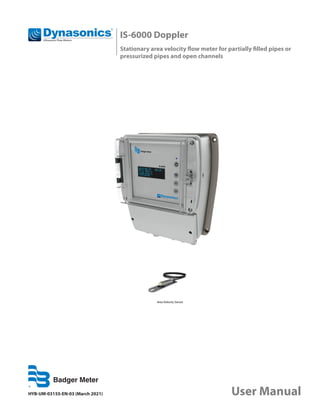
  • 1. Area Velocity Sensor HYB-UM-03155-EN-03 (March 2021) User Manual IS-6000 Doppler Stationary area velocity flow meter for partially filled pipes or pressurized pipes and open channels
  • 2. CONTENTS 1. General information . . . . . . . . . . . . . . . . . . . . . . . . . . . . . . . . . . . . . . . . . . . . . . . . . . . . . . . . . . . . . . . . . vii 1.1. Copyright . . . . . . . . . . . . . . . . . . . . . . . . . . . . . . . . . . . . . . . . . . . . . . . . . . . . . . . . . . . . . . . . . . . . vii 1.2. Data Protection and Security . . . . . . . . . . . . . . . . . . . . . . . . . . . . . . . . . . . . . . . . . . . . . . . . . . . . . . . vii 1.3. Liability . . . . . . . . . . . . . . . . . . . . . . . . . . . . . . . . . . . . . . . . . . . . . . . . . . . . . . . . . . . . . . . . . . . . . vii 1.4. EU Conformity Declaration . . . . . . . . . . . . . . . . . . . . . . . . . . . . . . . . . . . . . . . . . . . . . . . . . . . . . . . . . vii 1.5. Warnings and Safety Symbols . . . . . . . . . . . . . . . . . . . . . . . . . . . . . . . . . . . . . . . . . . . . . . . . . . . . . . . vii 2. General Safety Instructions . . . . . . . . . . . . . . . . . . . . . . . . . . . . . . . . . . . . . . . . . . . . . . . . . . . . . . . . . . . . . 8 2.1. Requirements for Personnel . . . . . . . . . . . . . . . . . . . . . . . . . . . . . . . . . . . . . . . . . . . . . . . . . . . . . . . . . 8 2.2. Intended Use . . . . . . . . . . . . . . . . . . . . . . . . . . . . . . . . . . . . . . . . . . . . . . . . . . . . . . . . . . . . . . . . . . 8 2.3. Workplace Safety . . . . . . . . . . . . . . . . . . . . . . . . . . . . . . . . . . . . . . . . . . . . . . . . . . . . . . . . . . . . . . . . 8 2.4. Operational Safety . . . . . . . . . . . . . . . . . . . . . . . . . . . . . . . . . . . . . . . . . . . . . . . . . . . . . . . . . . . . . . . 9 2.5. Product Safety . . . . . . . . . . . . . . . . . . . . . . . . . . . . . . . . . . . . . . . . . . . . . . . . . . . . . . . . . . . . . . . . . 9 2.6. Elecrtrical Safety . . . . . . . . . . . . . . . . . . . . . . . . . . . . . . . . . . . . . . . . . . . . . . . . . . . . . . . . . . . . . . . . 9 3. Product Description . . . . . . . . . . . . . . . . . . . . . . . . . . . . . . . . . . . . . . . . . . . . . . . . . . . . . . . . . . . . . . . . . 10 3.1. Scope of Delivery . . . . . . . . . . . . . . . . . . . . . . . . . . . . . . . . . . . . . . . . . . . . . . . . . . . . . . . . . . . . . . . 11 3.2. Storage . . . . . . . . . . . . . . . . . . . . . . . . . . . . . . . . . . . . . . . . . . . . . . . . . . . . . . . . . . . . . . . . . . . . . 11 3.3. Nameplate . . . . . . . . . . . . . . . . . . . . . . . . . . . . . . . . . . . . . . . . . . . . . . . . . . . . . . . . . . . . . . . . . . . 11 3.4. Measuring System . . . . . . . . . . . . . . . . . . . . . . . . . . . . . . . . . . . . . . . . . . . . . . . . . . . . . . . . . . . . . . 11 3.4.1. Transmitter . . . . . . . . . . . . . . . . . . . . . . . . . . . . . . . . . . . . . . . . . . . . . . . . . . . . . . . . . . . . . . 11 3.4.2. Software . . . . . . . . . . . . . . . . . . . . . . . . . . . . . . . . . . . . . . . . . . . . . . . . . . . . . . . . . . . . . . . . 13 3.4.2.1. System requirements . . . . . . . . . . . . . . . . . . . . . . . . . . . . . . . . . . . . . . . . . . . . . . . . . . . 13 3.4.3. Sensors . . . . . . . . . . . . . . . . . . . . . . . . . . . . . . . . . . . . . . . . . . . . . . . . . . . . . . . . . . . . . . . . . 14 3.4.3.1. Area Velocity Sensors . . . . . . . . . . . . . . . . . . . . . . . . . . . . . . . . . . . . . . . . . . . . . . . . . . 14 3.4.4. Sensor Mounting Systems . . . . . . . . . . . . . . . . . . . . . . . . . . . . . . . . . . . . . . . . . . . . . . . . . . . . . 15 4. Installation . . . . . . . . . . . . . . . . . . . . . . . . . . . . . . . . . . . . . . . . . . . . . . . . . . . . . . . . . . . . . . . . . . . . . . . 16 4.1. Installation Location . . . . . . . . . . . . . . . . . . . . . . . . . . . . . . . . . . . . . . . . . . . . . . . . . . . . . . . . . . . . . 16 4.2. Mounting the Transmitter . . . . . . . . . . . . . . . . . . . . . . . . . . . . . . . . . . . . . . . . . . . . . . . . . . . . . . . . . 16 4.3. Mounting the Sensors . . . . . . . . . . . . . . . . . . . . . . . . . . . . . . . . . . . . . . . . . . . . . . . . . . . . . . . . . . . . 17 4.3.1. Installating an Area Velocity Sensor . . . . . . . . . . . . . . . . . . . . . . . . . . . . . . . . . . . . . . . . . . . . . . . 17 4.4. Calibration . . . . . . . . . . . . . . . . . . . . . . . . . . . . . . . . . . . . . . . . . . . . . . . . . . . . . . . . . . . . . . . . . . . 17 5. Electrical Connection . . . . . . . . . . . . . . . . . . . . . . . . . . . . . . . . . . . . . . . . . . . . . . . . . . . . . . . . . . . . . . . . 18 5.1. Terminal Compartment . . . . . . . . . . . . . . . . . . . . . . . . . . . . . . . . . . . . . . . . . . . . . . . . . . . . . . . . . . . 18 5.1.1. Pin Assignments . . . . . . . . . . . . . . . . . . . . . . . . . . . . . . . . . . . . . . . . . . . . . . . . . . . . . . . . . . . 20 5.2. Connecting the Sensors . . . . . . . . . . . . . . . . . . . . . . . . . . . . . . . . . . . . . . . . . . . . . . . . . . . . . . . . . . . 22 Ultrasonic Flow Meters, IS-6000 Doppler Page ii March 2021 HYB-UM-03155-EN-03
  • 3. User Manual 5.2.1. Connecting Area Velocity Sensor . . . . . . . . . . . . . . . . . . . . . . . . . . . . . . . . . . . . . . . . . . . . . . . . 23 5.2.1.1. Connecting Multiple Area Velocity Sensors . . . . . . . . . . . . . . . . . . . . . . . . . . . . . . . . . . . . . 23 5.2.2. RS-485 /RS-232 Modbus Configuration . . . . . . . . . . . . . . . . . . . . . . . . . . . . . . . . . . . . . . . . . . . . . 23 5.3. Final Check of Electrical Connections . . . . . . . . . . . . . . . . . . . . . . . . . . . . . . . . . . . . . . . . . . . . . . . . . . 24 6. Communication with Transmitter . . . . . . . . . . . . . . . . . . . . . . . . . . . . . . . . . . . . . . . . . . . . . . . . . . . . . . . . . 25 6.1. Control Panel and LC-Display . . . . . . . . . . . . . . . . . . . . . . . . . . . . . . . . . . . . . . . . . . . . . . . . . . . . . . . 25 6.2. Wireless Communication WiFi . . . . . . . . . . . . . . . . . . . . . . . . . . . . . . . . . . . . . . . . . . . . . . . . . . . . . . . 26 6.3. Communication to the Transmitter via Ethernet LAN . . . . . . . . . . . . . . . . . . . . . . . . . . . . . . . . . . . . . . . . 27 7. Programming . . . . . . . . . . . . . . . . . . . . . . . . . . . . . . . . . . . . . . . . . . . . . . . . . . . . . . . . . . . . . . . . . . . . . 28 7.1. Login . . . . . . . . . . . . . . . . . . . . . . . . . . . . . . . . . . . . . . . . . . . . . . . . . . . . . . . . . . . . . . . . . . . . . . . 28 7.1.1. User Groups and Access Rights . . . . . . . . . . . . . . . . . . . . . . . . . . . . . . . . . . . . . . . . . . . . . . . . . . 29 7.2. Menu Structure . . . . . . . . . . . . . . . . . . . . . . . . . . . . . . . . . . . . . . . . . . . . . . . . . . . . . . . . . . . . . . . . 30 7.2.1. Overview of Main Menu Items and Function of Corresponding Submenus . . . . . . . . . . . . . . . . . . . . . . 31 7.3. Settings for Language and Location . . . . . . . . . . . . . . . . . . . . . . . . . . . . . . . . . . . . . . . . . . . . . . . . . . . 32 7.4. Home - Overview . . . . . . . . . . . . . . . . . . . . . . . . . . . . . . . . . . . . . . . . . . . . . . . . . . . . . . . . . . . . . . . 33 7.5. Graph - Data Visualization . . . . . . . . . . . . . . . . . . . . . . . . . . . . . . . . . . . . . . . . . . . . . . . . . . . . . . . . . 34 7.5.1. Three-Day Display . . . . . . . . . . . . . . . . . . . . . . . . . . . . . . . . . . . . . . . . . . . . . . . . . . . . . . . . . . 34 7.5.2. Current . . . . . . . . . . . . . . . . . . . . . . . . . . . . . . . . . . . . . . . . . . . . . . . . . . . . . . . . . . . . . . . . . 35 7.5.3. History . . . . . . . . . . . . . . . . . . . . . . . . . . . . . . . . . . . . . . . . . . . . . . . . . . . . . . . . . . . . . . . . . 36 7.5.4. Velocity Profile . . . . . . . . . . . . . . . . . . . . . . . . . . . . . . . . . . . . . . . . . . . . . . . . . . . . . . . . . . . . 37 7.5.5. Settings . . . . . . . . . . . . . . . . . . . . . . . . . . . . . . . . . . . . . . . . . . . . . . . . . . . . . . . . . . . . . . . . 38 7.6. Download, Data Transfer . . . . . . . . . . . . . . . . . . . . . . . . . . . . . . . . . . . . . . . . . . . . . . . . . . . . . . . . . . 39 7.6.1. Download . . . . . . . . . . . . . . . . . . . . . . . . . . . . . . . . . . . . . . . . . . . . . . . . . . . . . . . . . . . . . . . 39 7.6.2. Setting . . . . . . . . . . . . . . . . . . . . . . . . . . . . . . . . . . . . . . . . . . . . . . . . . . . . . . . . . . . . . . . . . 41 7.7. Parameter - Parameterization . . . . . . . . . . . . . . . . . . . . . . . . . . . . . . . . . . . . . . . . . . . . . . . . . . . . . . . 41 7.7.1. Geometry . . . . . . . . . . . . . . . . . . . . . . . . . . . . . . . . . . . . . . . . . . . . . . . . . . . . . . . . . . . . . . . 42 7.7.1.1. Sludge Level . . . . . . . . . . . . . . . . . . . . . . . . . . . . . . . . . . . . . . . . . . . . . . . . . . . . . . . . 47 7.7.2. Water Level . . . . . . . . . . . . . . . . . . . . . . . . . . . . . . . . . . . . . . . . . . . . . . . . . . . . . . . . . . . . . . 47 7.7.3. Measurement Range . . . . . . . . . . . . . . . . . . . . . . . . . . . . . . . . . . . . . . . . . . . . . . . . . . . . . . . . 51 7.7.4. Calibration . . . . . . . . . . . . . . . . . . . . . . . . . . . . . . . . . . . . . . . . . . . . . . . . . . . . . . . . . . . . . . . 55 7.7.5. Replacement . . . . . . . . . . . . . . . . . . . . . . . . . . . . . . . . . . . . . . . . . . . . . . . . . . . . . . . . . . . . . 57 7.7.6. Temperature . . . . . . . . . . . . . . . . . . . . . . . . . . . . . . . . . . . . . . . . . . . . . . . . . . . . . . . . . . . . . 62 7.8. I/Os – Digital and analog inputs and outputs . . . . . . . . . . . . . . . . . . . . . . . . . . . . . . . . . . . . . . . . . . . . . 62 Page iii March 2021 HYB-UM-03155-EN-03
  • 4. Ultrasonic Flow Meters, IS-6000 Doppler 7.8.1. Analog Input . . . . . . . . . . . . . . . . . . . . . . . . . . . . . . . . . . . . . . . . . . . . . . . . . . . . . . . . . . . . . 62 7.8.2. Analog Output . . . . . . . . . . . . . . . . . . . . . . . . . . . . . . . . . . . . . . . . . . . . . . . . . . . . . . . . . . . . 65 7.8.3. Digital Input . . . . . . . . . . . . . . . . . . . . . . . . . . . . . . . . . . . . . . . . . . . . . . . . . . . . . . . . . . . . . 66 7.8.4. Digital Output . . . . . . . . . . . . . . . . . . . . . . . . . . . . . . . . . . . . . . . . . . . . . . . . . . . . . . . . . . . . 66 7.8.5. Users Values . . . . . . . . . . . . . . . . . . . . . . . . . . . . . . . . . . . . . . . . . . . . . . . . . . . . . . . . . . . . . . 70 7.9. Settings – Data Logging and Display . . . . . . . . . . . . . . . . . . . . . . . . . . . . . . . . . . . . . . . . . . . . . . . . . . . 70 7.9.1. Logging . . . . . . . . . . . . . . . . . . . . . . . . . . . . . . . . . . . . . . . . . . . . . . . . . . . . . . . . . . . . . . . . 71 7.9.2. Units . . . . . . . . . . . . . . . . . . . . . . . . . . . . . . . . . . . . . . . . . . . . . . . . . . . . . . . . . . . . . . . . . . 72 7.9.3. Displayed Units . . . . . . . . . . . . . . . . . . . . . . . . . . . . . . . . . . . . . . . . . . . . . . . . . . . . . . . . . . . . 74 7.9.4. Totalizer . . . . . . . . . . . . . . . . . . . . . . . . . . . . . . . . . . . . . . . . . . . . . . . . . . . . . . . . . . . . . . . . 75 7.10. Communication – Network Settings . . . . . . . . . . . . . . . . . . . . . . . . . . . . . . . . . . . . . . . . . . . . . . . . . . . 76 7.10.1. Network . . . . . . . . . . . . . . . . . . . . . . . . . . . . . . . . . . . . . . . . . . . . . . . . . . . . . . . . . . . . . . . . 77 7.10.1.1 Manual Input and Changing the IP Address . . . . . . . . . . . . . . . . . . . . . . . . . . . . . . . . . . . . 78 7.10.2. SMS . . . . . . . . . . . . . . . . . . . . . . . . . . . . . . . . . . . . . . . . . . . . . . . . . . . . . . . . . . . . . . . . . . . 85 7.10.3. FTP . . . . . . . . . . . . . . . . . . . . . . . . . . . . . . . . . . . . . . . . . . . . . . . . . . . . . . . . . . . . . . . . . . . 86 7.10.4. Modbus . . . . . . . . . . . . . . . . . . . . . . . . . . . . . . . . . . . . . . . . . . . . . . . . . . . . . . . . . . . . . . . . 87 7.10.5. Serial . . . . . . . . . . . . . . . . . . . . . . . . . . . . . . . . . . . . . . . . . . . . . . . . . . . . . . . . . . . . . . . . . . 89 7.11. Diagnosis . . . . . . . . . . . . . . . . . . . . . . . . . . . . . . . . . . . . . . . . . . . . . . . . . . . . . . . . . . . . . . . . . . . . 91 7.11.1. Log Files . . . . . . . . . . . . . . . . . . . . . . . . . . . . . . . . . . . . . . . . . . . . . . . . . . . . . . . . . . . . . . . . 91 7.11.2. Data . . . . . . . . . . . . . . . . . . . . . . . . . . . . . . . . . . . . . . . . . . . . . . . . . . . . . . . . . . . . . . . . . . . 92 7.12. Extras . . . . . . . . . . . . . . . . . . . . . . . . . . . . . . . . . . . . . . . . . . . . . . . . . . . . . . . . . . . . . . . . . . . . . . 92 7.12.1. Language and Location . . . . . . . . . . . . . . . . . . . . . . . . . . . . . . . . . . . . . . . . . . . . . . . . . . . . . . 93 7.12.2. Date Time . . . . . . . . . . . . . . . . . . . . . . . . . . . . . . . . . . . . . . . . . . . . . . . . . . . . . . . . . . . . . . . 95 7.12.3. LC Display . . . . . . . . . . . . . . . . . . . . . . . . . . . . . . . . . . . . . . . . . . . . . . . . . . . . . . . . . . . . . . . 96 7.12.4. Power Management . . . . . . . . . . . . . . . . . . . . . . . . . . . . . . . . . . . . . . . . . . . . . . . . . . . . . . . . . 97 7.12.5. Backup & Update . . . . . . . . . . . . . . . . . . . . . . . . . . . . . . . . . . . . . . . . . . . . . . . . . . . . . . . . . . . 98 7.13. Abbreviations . . . . . . . . . . . . . . . . . . . . . . . . . . . . . . . . . . . . . . . . . . . . . . . . . . . . . . . . . . . . . . . . 100 8. Service . . . . . . . . . . . . . . . . . . . . . . . . . . . . . . . . . . . . . . . . . . . . . . . . . . . . . . . . . . . . . . . . . . . . . . . . 101 8.1. Cleaning, Maintenance and Care . . . . . . . . . . . . . . . . . . . . . . . . . . . . . . . . . . . . . . . . . . . . . . . . . . . . 101 8.2. Troubleshooting . . . . . . . . . . . . . . . . . . . . . . . . . . . . . . . . . . . . . . . . . . . . . . . . . . . . . . . . . . . . . . 101 8.2.1. Error Codes . . . . . . . . . . . . . . . . . . . . . . . . . . . . . . . . . . . . . . . . . . . . . . . . . . . . . . . . . . . . . 101 8.2.2. Reset to Factory Settings . . . . . . . . . . . . . . . . . . . . . . . . . . . . . . . . . . . . . . . . . . . . . . . . . . . . . 102 8.3. Return / Repair . . . . . . . . . . . . . . . . . . . . . . . . . . . . . . . . . . . . . . . . . . . . . . . . . . . . . . . . . . . . . . . 104 8.4. Disposal . . . . . . . . . . . . . . . . . . . . . . . . . . . . . . . . . . . . . . . . . . . . . . . . . . . . . . . . . . . . . . . . . . . . 104 9. Operating Principle . . . . . . . . . . . . . . . . . . . . . . . . . . . . . . . . . . . . . . . . . . . . . . . . . . . . . . . . . . . . . . . . . 105 9.1. Doppler Flow Meter . . . . . . . . . . . . . . . . . . . . . . . . . . . . . . . . . . . . . . . . . . . . . . . . . . . . . . . . . . . . 105 9.2. Pulse Wave Doppler (PW) . . . . . . . . . . . . . . . . . . . . . . . . . . . . . . . . . . . . . . . . . . . . . . . . . . . . . . . . . 106 Page iv March 2021 HYB-UM-03155-EN-03
  • 5. LIST OF TABLES Table 1: Error codes (depending on the configuration of the measuring system) . . . . . . . . . . . . . . . . . . . . . . . . . . . . 100 Table 2: Specific roughness coefficients (Manning & Strickler coefficients) for closed conduit, partly full metal pipesl . . . . . 109 Table 3: Specific roughness coefficients (Manning & Strickler coefficients) for closed conduit, partly full non-metal pipesl . 110 Table 4: Specific roughness coefficients (Manning & Strickler coefficients) for lined or built-up metal channels . . . . . . . . . 110 Table 5: Specific roughness coefficients (Manning & Strickler coefficients) for lined or built-up non-metal channels . . . . . . 111 Table 6: Specific roughness coefficients (Manning & Strickler coefficients) for excavated or dredged channels . . . . . . . . . 111 Table 7: Specific roughness coefficients (Manning & Strickler coefficients) for regular/irregular sections . . . . . . . . . . . . . 111 User Manual 9.3. Ultrasonic Signal Diagnostics . . . . . . . . . . . . . . . . . . . . . . . . . . . . . . . . . . . . . . . . . . . . . . . . . . . . . . 106 10. Technical Data . . . . . . . . . . . . . . . . . . . . . . . . . . . . . . . . . . . . . . . . . . . . . . . . . . . . . . . . . . . . . . . . . . . . 107 10.1. Transmitter . . . . . . . . . . . . . . . . . . . . . . . . . . . . . . . . . . . . . . . . . . . . . . . . . . . . . . . . . . . . . . . . . . 107 10.2. Area Velocity Sensor . . . . . . . . . . . . . . . . . . . . . . . . . . . . . . . . . . . . . . . . . . . . . . . . . . . . . . . . . . . . 108 11. Annex . . . . . . . . . . . . . . . . . . . . . . . . . . . . . . . . . . . . . . . . . . . . . . . . . . . . . . . . . . . . . . . . . . . . . . . . . 109 11.1. Roughness Coefficients . . . . . . . . . . . . . . . . . . . . . . . . . . . . . . . . . . . . . . . . . . . . . . . . . . . . . . . . . . 109 11.1.1. Closed conduit, Partly Full Metal Pipes . . . . . . . . . . . . . . . . . . . . . . . . . . . . . . . . . . . . . . . . . . . . 109 11.1.2. Closed Conduit, Partly Full Non-Metal Pipes . . . . . . . . . . . . . . . . . . . . . . . . . . . . . . . . . . . . . . . . 110 11.1.3. Lined or Built-Up Metal Channels . . . . . . . . . . . . . . . . . . . . . . . . . . . . . . . . . . . . . . . . . . . . . . . 110 11.1.4. Lined or Built-Up Non-Metal Channels . . . . . . . . . . . . . . . . . . . . . . . . . . . . . . . . . . . . . . . . . . . . 111 11.1.5. Excavated or Dredged Channels . . . . . . . . . . . . . . . . . . . . . . . . . . . . . . . . . . . . . . . . . . . . . . . . 111 11.1.6. Natural Channels . . . . . . . . . . . . . . . . . . . . . . . . . . . . . . . . . . . . . . . . . . . . . . . . . . . . . . . . . . 111 11.2. Bibliography . . . . . . . . . . . . . . . . . . . . . . . . . . . . . . . . . . . . . . . . . . . . . . . . . . . . . . . . . . . . . . . . . 111 Page v March 2021 HYB-UM-03155-EN-03
  • 6. LIST OF FIGURES Figure 1: Combined ultrasonic velocity and water level measurement with an area velocity sensor (combination sensor) . . 10 Figure 2: Nameplate (example) . . . . . . . . . . . . . . . . . . . . . . . . . . . . . . . . . . . . . . . . . . . . . . . . . . . . . . . . . . . . 11 Figure 3: a),b) Front view of transmitter housing for wall installation, enclosure dimensions (in mm) c),d) top view and side view, dimensions (in mm) e) bottom view . . . . . . . . . . . . . . . . . . . . . . . . . . . . . . . . . . . . . . . . . . . . . . . . . . . . . . . . . . . . . . . . . . . . . . . 12 Figure 4: a) Scheme for combined ultrasonic velocity (v) and water level (h) measurement b) Area velocity sensor incl. mounting plate c) Dimensions (length, depth in mm), top view d) Dimensions (height in mm), side view . . . . . . . . . . . . . . . . . . . . . . . . . . . . . . . . . . . . . . . . . . . . . . . . . . . . . . 14 Figure 5: Example for sensor mounting system (tension ring) in a pipe . . . . . . . . . . . . . . . . . . . . . . . . . . . . . . . . . . . 15 Figure 6: Installation of sensors against flow direction (1) and in flow direction (2) . . . . . . . . . . . . . . . . . . . . . . . . . . . . 17 Figure 7: Overview terminal compartment . . . . . . . . . . . . . . . . . . . . . . . . . . . . . . . . . . . . . . . . . . . . . . . . . . . . . 19 Figure 8: Overview pin assignment . . . . . . . . . . . . . . . . . . . . . . . . . . . . . . . . . . . . . . . . . . . . . . . . . . . . . . . . . 20 Figure 9: Pin assignment (# 71-78) for the connection of area velocity sensor . . . . . . . . . . . . . . . . . . . . . . . . . . . . . . . 23 Figure 10: Pin assignments # 21-26 for connection on RS-485 2-wire / 4-wire and RS-232 (pin assignment for aluminium enclosure – integrated 4G/3G/2G modem) . . . . . . . . . . . . . . . . . . . . . . . . . . . . . . . . . 23 Figure 11: Control panel and display functions . . . . . . . . . . . . . . . . . . . . . . . . . . . . . . . . . . . . . . . . . . . . . . . . . . 25 Figure 12: Height of sediment layer in a cross section (sludge level) . . . . . . . . . . . . . . . . . . . . . . . . . . . . . . . . . . . . . 47 Figure 13: Doppler Principle . . . . . . . . . . . . . . . . . . . . . . . . . . . . . . . . . . . . . . . . . . . . . . . . . . . . . . . . . . . . . 104 Ultrasonic Flow Meters, IS-6000 Doppler Page vi March 2021 HYB-UM-03155-EN-03
  • 7. 1. GENERAL INFORMATION This user manual provides all necessary information for the operation and the efficient and safe use of the IS-6000 Doppler flow meter. It contains important information on product identification, storage, installation, commissioning, operation, maintenance and disposal of the device. Before putting the device into operation, read this user manual carefully. To prevent possible injuries to the user and damage, use the device only for the intended use described below. Always keep this document handy in the vicinity of the device! If you do not understand the contents of this document, contact the manufacturer. In no case may the manufacturer be held reliable for any damage or injury caused by misunderstanding of the information. 1.1. Copyright All rights reserved. The contents and works in this document are subject to German copyright. Contributions from third parties are identified as such. No part of this documentation may be reproduced in any form, stored or transferred, neither electronically, mechanically, photo-technically, by recording on data media or otherwise, as long as no expressly written authorization from the publisher is present. 1.2. Data Protection and Security All data should be backed-up prior to the installation of any peripheral storage device. The manufacturer will not be responsible for any loss of data resulting from the use or misuse of this or any other product from the manufacturer. Data security is given by personated login with username and password. Data will be saved on the server with appropriate security measures for protection against data loss, data abuse and unauthorized data modifications. There are inherent security risks in transmitting data via the internet. It is not possible to safeguard completely against unauthorized access by third parties. The use of contact data published within the framework of the imprint obligation by third parties for the transmission of not expressly requested advertising and information material is hereby expressly rejected. 1.3. Liability In case of inappropriate or unintended use, no liability for the proper function of the device can be assumed. Improper installation and operation of the device will void the warranty. The manufacturer has made every effort to assure the accuracy of the contents of this manual and the software. However, the manufacturer can offer no guarantee that the information provided is accurate and/or free of error. The information provided in this manual is subject to change without notice at any time. The manufacturer reserves the right to alter designs, layouts or software without prior notification and will not be liable in any way for possible consequences of such changes. 1.4. EU Conformity Declaration The manufacturer hereby declares that this product complies with Directive 2014/30/EU, 2014/35/EU, 014/53/EU, 2014/65/EU. 1.5. Warnings and Safety Symbols Depending on the hazard level, warnings are displayed as follows. Immediate danger. Indicates a potentially or imminently hazardous situation which, if not avoided, will result in death or serious injury. Medium risk. Indicates a potentially or imminently hazardous situation which, if not avoided, could result in death or serious injury. Minor risk. Indicates a potentially hazardous situation that may result in minor or moderate injury or damage. MPORTANT I Important handling instruction. Indicates a situation which, if not avoided, may cause damage to the device. Information that requires special emphasis. OTE: N This symbol indicates helpful notes and information for handling the device. User Manual Page vii March 2021 HYB-UM-03155-EN-03
  • 8. 2. GENERAL SAFETY INSTRUCTIONS 2.1. Requirements for Personnel Installation, electrical connections, commissioning, operation, and maintenance of the device must be carried out by qualified, specially trained and authorized personnel. Personal injuries and serious damage to the device are caused by insufficiently qualified personnel. Qualified personnel: • Are persons who, through their professional training and education, are familiar with the safety guidelines of electrical and automation engineering. • Are persons who, as project, commissioning, and installation personnel, are authorized to commission, ground and label circuits and devices/systems in accordance with the standards of safety engineering. • Must be able to safely assess the results of their work and must be familiar with the contents of these operating instructions. Special trained personnel: • Are persons, for example fitters or electricians, who can perform various tasks such as transport, assembly and installation of the product under the supervision of an authorized person. The persons must have experience in handling the product. Authorized personnel: • Are persons who are indented to work on the basis of legal regulations or have been approved by the manufacturer for certain activities. The following requirements must be met: • The user manual must be read carefully and fully understood by qualified personnel. Instructions must be followed. • Qualified personnel must be trained and authorized by the plant operator. • During work on and with the device, the required personal protective equipment must always be worn. • All applicable national standards, safety requirements and accident prevention regulation have to be observed. 2.2. Intended Use IMPROPER USE CAN SERIOUSLY COMPROMISE THE SAFETY OF THE DEVICE. THE DEVICE IS EXCLUSIVELY DESIGNED TO BE USED FOR PURPOSES AS DESCRIBED BELOW. KEEP WITHIN THE SPECIFIED PRESSURE AND TEMPERATURE RANGE WHILE USING THE DEVICE. RESISTANCE OF ALL FLUID-WETTED PARTS OF THE DEVICE AGAINST THE MEASURED FLUID MUST BE MADE SURE IN ORDER TO AVOID CORROSION AND ABRASION. OTE: N The manufacturer is not liable for any damage resulting from improper use or use for other than the intended purpose. The IS-6000 Doppler stationary pulse-Doppler System is a permanent velocity area flow meter that measures flow in full and partially full pipes with 4…80 in. (100…2000 mm) in diameter, and in open channels with water depths from 1.5…80 in. (0.04…2 m) . 2.3. Workplace Safety During work on and with the device the required personal protective equipment must always be worn. All applicable national standards, safety requirements and accident prevention regulation must be observed. General Safety Instructions Page 8 March 2021 HYB-UM-03155-EN-03
  • 9. 2.4. Operational Safety Operate the device in proper technical condition and fail-safe condition only. The operator is responsible for interference-free operation of the device. 2.5. Product Safety This measuring device is designed in accordance with good engineering practice to meet state-of-the-art safety requirements. It has been tested and left the factory in a condition in which it is safe to operate. It meets general safety standards and legal requirements. It also complies with the EU directives listed in the device-specific EU Declaration of Conformity. 2.6. Elecrtrical Safety DISCONNECT DEVICE SINCE THE DEVICE CANNOT BE SWITCHED OFF AT THE HOUSING, IT IS ABSOLUTELY NECESSARY TO CONNECT THE SYSTEM TO AN EXTERNAL DISCONNECTING DEVICE. DANGEROUS CONTACT VOLTAGES • THE FUNCTIONAL EARTHING IS NOT IDENTICAL TO THE PROTECTIVE EARTHING ACCORDING TO DIN VDE 0100! • EMC GROUND CONNECTORS ONLY FULFIL SECONDARY MEASURES FOR PROTECTION AGAINST DANGEROUS CONTACT VOLTAGES. • THE GREEN-YELLOW WIRES OF THE PROTECTIVE CONDUCTOR (PE) FULFIL THE MEASURES FOR PROTECTION AGAINST DANGEROUS CONTACT VOLTAGES, BUT NOT THE REQUIREMENTS OF EMC DIRECTIVE 2014/30/EU. • WHEN EARTHING A SYSTEM, TAKE APPROPRIATE PROTECTIVE AND FUNCTIONAL MEASURES IN ACCORDANCE WITH DIN VDE 0100 AND EMC DIRECTIVE 2014/30/EU. ! PROTECTIVE GROUNDING SUITABLE MEASURES FOR ERROR PROTECTION MUST BE CARRIED OUT. THE CONDUCTIVE SYSTEM PARTS TO BE PROTECTED MUST BE CONNECTED TO A SUITABLE EARTHING CONDUCTOR VIA THE PE CONDUCTOR, SO THAT THE SYSTEM PARTS WITH A FAULT ARE SWITCHED OFF BY OVERCURRENT PROTECTION DEVICES. Symbols Description Protective conductor connection This symbol refers to the protective conductor connection of the device. Depending on the type of installation, the device may only be operated with a suitable protective conductor connection in accordance with the applicable laws and regulations L Phase conductor N Neutral conductor General Safety Instructions Page 9 March 2021 HYB-UM-03155-EN-03
  • 10. 3. PRODUCT DESCRIPTION The IS-6000 Doppler stationary ultrasonic flow meter continuously measures the flow of water and wastewater in pressurized and partially filled pipes and in open channels with water depths from 1.5…80 in. (0.04…2 m). As a standard, the flow meter consists of a transmitter and an ultrasonic area velocity sensor for combined velocity and water level measurement (see Figure 1). Discharge is then calculated by multiplication of the average flow velocity and the wetted cross-sectional area. The transmitter allows connection of up to 3 ultrasonic area velocity sensors for simultaneous measurement at up to 3 different measurement spots in one cross-section. Alternatively, additional external water level sensors (for example, a hydrostatic level sensor or an ultrasonic down-looking level sensor) can be connected to the system depending on specific site conditions, providing accurate water level measurement in case of water level fluctuations. For discharge measurement in pressurized and partially filled pipes, insertion sensors are used. Insertion sensors are installed into the existing pipe work through ball valves allowing the installation and removal of the entire sensor for repair, replacement, or cleaning without dewatering the pipe. Figure 1: Combined ultrasonic velocity and water level measurement with an area velocity sensor (combination sensor) The IS-6000 Doppler transmitter incorporates all the required algorithms and software for measurement accuracy and repeatability. Parameterization of the measurement site, data logging, visualization and data transfer is possible by using the browser-based control and management user interface, which can be run in any standard web browser via PC, notebook, tablet or smart phone, regardless of location, time and operating system. Applications: Based on the pulsed wave Doppler principle, the flow measurement of IS-6000 Doppler meter requires suspended particles or gas bubbles in the flowing liquid as reflectors of the acoustic signals. Therefore, the meter is ideally suited for continuous flow monitoring in slightly to heavily polluted media. • Wastewater treatment plants (influent measurement, real-time process control, effluent measurement) • Wastewater collection systems (infiltration studies, hydraulic model calibration, event notification, long term trend analysis) • Urban drainage Product Description Page 10 March 2021 HYB-UM-03155-EN-03
  • 11. 3.1. Scope of Delivery MPORTANT I Check the packaging and the contents for damage. Check that delivery is complete and agrees with the shipping documents and your order. If damages occurred or any items are missing, please contact the manufacturer. The scope of delivery • IS-6000 Doppler transmitter • Area velocity sensor or insertion sensor including cable • User manual Optional Accessories • External hydrostatic level sensor or external ultrasonic level sensor • Integrated LTE/HSPA+/GPRS (4G/3G/2G) modem incl. 4G/LTE dipole antenna • Mounting systems (sensor mounting plates, in-pipe tension rings, scissors rings) 3.2. Storage Store the equipment in a dry and dust-free place. Avoid durable exposure to direct sunlight. Store the device ideally in its original packaging. Storage temperature: -4…158° F (-20…70° C), ideally 68° F(20° C). 3.3. Nameplate OTE: N Check the device nameplate to make sure that the device is delivered according to your order. The nameplate (see Figure 2) indicates important data for identification and use of the measuring system. 1 2 3 4 5 6 7 8 9 Manufacturer name Product name Serial number transmitter (S/N) Power supply data Ambient temperature range Manufacturing date mm/yyyy Network number IP protection class CE mark Figure 2: Nameplate (example) 3.4. Measuring System 3.4.1. Transmitter The transmitter (see Figure 3 on page 12) is designed to operate ultrasonic velocity sensors and to calculate the flow rate. The flow computer incorporates all of the required algorithms and software to ensure accuracy and repeatability of the measurements. The IP66 (NEMA 4) compact flow display computer has a 4 lines × 20 characters alphanumeric LC display and a 4-button keypad. All configuration data, measurement data, and calculated data are stored on a 16GB Micro-SD card. It controls the measurements, calculates the flow rate and provides freely programmable current outputs, status alarm, frequency outputs and totalizer readings. . Product Description Page 11 March 2021 HYB-UM-03155-EN-03
  • 12. OTE: N For use and installation of IS-6000 Doppler meter in potentially explosive atmospheres, the transmitter is connected to an explosion-proofed stationary Ex-flow rate module (according to ATEX Directive 2014/34/EU). The Ex-flow rate module comes with an area velocity sensor with an explosion-proof connection cable. For detailed description of the Ex-flow rate module and the connection to the IS-6000 Doppler transmitter, an additional user manual is provided by the manufacturer. a) b) c) d) 139 139 e) Figure 3: a),b) Front view of transmitter housing for wall installation, enclosure dimensions (in mm) c),d) top view and side view, dimensions (in mm) e) bottom view Product Description Page 12 March 2021 HYB-UM-03155-EN-03
  • 13. 3.4.2. Software The IS-6000 Doppler flow meter is programmed and operated by a browser-based user interface that simply can be run via WiFi or LAN connection in any standard web browser via PC, notebook, tablet or smart phone, regardless of location, time and operating system. The graphical user interface is menu-driven for rapid commissioning, easy parameterization of the measurement site and data visualization and management. Main features are: • Intuitive menu-driven user interface • Direct communication (WiFi) with measuring system • Automatic identification of measuring system via system-specific IP address • Status information of measuring system, alarm functions • Simple parameterization and commissioning of measuring system • Flexible graphical data visualization (for example real-time zoomable data and time series, data history, velocity profiles) • Data logging of incoming data and easy data transfer • Remote system diagnostics, service and maintenance • Protection from unauthorized access through individual access authorization 3.4.2.1. System requirements • Network connection (WiFi, LAN) • Standard latest web browser, for example: Internet Explorer, Firefox, Chrome, Safari, Opera, Android Browser. Product Description Page 13 March 2021 HYB-UM-03155-EN-03
  • 14. 3.4.3. Sensors As a standard, the IS-6000 Doppler meter comes with an area velocity sensor for ultrasonic flow velocity and water level measurement. Depending on the measurement task and site conditions external sensors for example for water level measurement such as a pressure sensor or a non-contact ultrasonic level sensor can be connected via 4…20 mA interfaces. 3.4.3.1. Area Velocity Sensors The mouse-type area velocity sensor measures flow velocity and water level based on the pulse (echo) coherent method corrected by an embedded temperature sensor. The small sensor dimensions mean less interference resulting in more accurate velocity measurements, especially under low flow conditions. a) b) c) d) Figure 4: a) Scheme for combined ultrasonic velocity (v) and water level (h) measurement b) Area velocity sensor incl. mounting plate c) Dimensions (length, depth in mm), top view d) Dimensions (height in mm), side view Product Description Page 14 March 2021 HYB-UM-03155-EN-03
  • 15. 3.4.4. Sensor Mounting Systems All sensors can be attached to a mounting plate, spring or scissors rings. The sensor is first attached to a carrier to be slid onto any of the compatible mounting systems. This maintains a height suitable for measuring flow rates and velocities at very low water levels. To install the sensors in rectangular, trapezoidal or earthen channels, use the sensor mounting plate. Stainless steel spring rings simplify sensor installation in cylindrical pipes. Six standard diameter sizes from 8…24 in. (200…600 mm) are available. Before entering the manhole, the sensor and the cable can be fastened in place to the downstream edge of the ring. The self-expanding device sits tight by expanding the band for a friction fit inside the pipe. The adjustable scissors ring is installed in large diameter pipes from 20…57 in. (500…1450 mm). It consists of a base section and one or more pairs of extensions to fit the size of the pipe and a scissors mechanism.      Pipe  Tension ring with pre-drilled holes to fasten sensor cable to the ring  Area velocity sensor on sensor mounting plate Figure 5: Example for sensor mounting system (tension ring) in a pipe Product Description Page 15 March 2021 HYB-UM-03155-EN-03
  • 16. 4. INSTALLATION MPORTANT I Be advised that possible mounting and connection errors and their effects are beyond our control. Therefore, the manufacturer cannot be held responsible for damages as a result of incorrect handling, installation and maintenance of the equipment. 4.1. Installation Location For reliable, continuous stability and accuracy of the device, follow the instructions below: • Choose a measuring site with a steady distribution of flow velocity over the cross-section, avoiding highly turbulent flow conditions. • Avoid measuring sites with sediment accumulation or deposits. • Always observe ambient temperature at the installation site. Avoid exposure to heat, frost, extreme temperature fluctuations and direct sunlight. • Make sure that the device is protected from mechanical impacts and vibration. • If using the device under corrosive or aggressive atmospheric conditions, make sure the location is well ventilated. • Protect the transmitter from flooding. 4.2. Mounting the Transmitter OTE: N Mount the transmitter in a position that is protected against direct sunlight and rainfall. 1. Select a proper position on a flat wall surface. Make sure to have a sufficient power supply in the vicinity of the transmitter. Make sure the cabling is safe. 2. Mark the upper drill hole at the positions of the upper hanger in the middle on top of the transmitter enclosure. 3. Drill a hole for corresponding wall plug for fixing screw at the marked point. 4. Mount the transmitter with fixing screw on the wall. Use suitable screws and plugs depending on the wall construction and installation conditions. Make sure the enclosure is aligned horizontally. 5. Then mark the holes for the last two drillings on the left and right site on the bottom of the enclosure and follow the procedure described above. 6. Be sure to tighten the screws firmly. Temperature Strip For monitoring ambient temperatures higher than 104° F (40° C), view the yellow self-adhesive temperature strip inside the transmitter enclosure. An increase in temperature in the range of 104…160° F (40…71° C) will cause an irreversible change of color of the specific segment from light grey to dark grey. The dark color will remain even after subsequent cooling, indicating the maximum temperature that has been reached. Indicated temperature segments: 104° F (40° C), 109.4° F (43° C), 114.8° F (46° C), 120.2° F (49° C), 129.2° F (54° C), 140° F (60° C), 150.8° F (66° C), 159.8° F (71° C). OTE: N Always check temperature strip when opening the enclosure. The temperature strip is for quality assurance and warranty demands. Removal of the strip invalidates the warranty. Installation Page 16 March 2021 HYB-UM-03155-EN-03
  • 17. 4.3. Mounting the Sensors SENSORS IN USE MUST BE PROTECTED FROM MECHANICAL DAMAGE DUE TO IMPACTS OR ABRASION (FOR EXAMPLE FROM COARSE SEDIMENT LOAD OR ABRASIVE SEDIMENT MATERIAL). Special mounting systems are available to make sensor installation easier and reduce installation time. Sensors are first mounted to carriers that can be easily attached to any of the compatible mounting system. The signal cable is already fixed at the sensor. The cable length has to be adapted to site conditions. Always make sure that sensor cables connected to the transmitter are mounted firmly to the wall as tripping on the cables can cause both serious personal injury and permanent damage to cables and connectors. Check again, that the measuring window is not affected by the cables. ANY ADJUSTMENTS OF CABLE LENGTHS MUST BE CARRIED OUT SOLELY BY THE MANUFACTURER. PLEASE CONTACT OUR SERVICE TECHNICIANS. 4.3.1. Installating an Area Velocity Sensor Normally, flow velocity is measured against the flow direction due to possible turbulences caused by the sensor itself and the cable that might affect the measurement. However, the sensor measures flow velocity regardless of the flow direction (see Figure 6). Readings measured with sensors installed against the flow direction are registered as positive values (+v) and vice versa (-v).   Figure 6: Installation of sensors against flow direction (1) and in flow direction (2) 4.4. Calibration For all flow velocity measuring systems for partially filled cross-sections that are installed in existing pipelines, a calibration of the measuring site (measurement of network, tracer measurement) is recommended in order to receive an optimum measuring accuracy. During calibration, the water level at the measuring site should be at least 4 in. (10 cm). For instructions for calibration of measuring sites, see DIN EN ISO 748 [2]. OTE: N The calculation for calibration is performed via software in the calibration menu of user interface ( Parameter  Calibration). Installation Page 17 March 2021 HYB-UM-03155-EN-03
  • 18. 5. ELECTRICAL CONNECTION • Improper connection can cause injury or death. The electrical connection must be carried out by a certified electrician. • Observe the national regulations for electrical installations! By handling products that are supplied by electrical voltage, you must observe the valid IEC instructions, especially IEC 60364, IEC 61558, IEC 60335, IEC 60598-1 and IEC 60065. • Before opening an instrument, pull off the main plug and make sure that the instrument is without power supply. Parts, construction groups or instruments must only be set into operation if they are built into a housing and protected against touching. During installation they must be without power. Only use tools at the instruments, parts or construction groups the devices are disconnected from the supply voltage and the electric loads stored in the construction groups inside the instrument are unloaded. Conducting cables or conductors that are connected to the instrument, part or construction group must be checked continuously for isolation faults or sites of fractures. If a fault is found in the supply line, the instrument must be switched off immediately until the defective line has been replaced. • By using construction elements or groups please make sure that the features for electrical sizes are observed according to the respective description. In case it is not possible to clarify clearly for a non-commercial end-user which electrical variables are valid for a part or a construction group, how external wiring is to be undertaken, which external components or additional devices can be connected and which connection values these external components may have, always contact an expert for respective information. • Before operation, generally check if the instrument or construction group is suitable for the field of application. If there is any doubt, you must confer with a technical expert or the manufacturer of the used construction group. • Compare specifications on the nameplate and check for the correct supply voltage on the nameplate. • Feed the power supply cable and signal cables through the appropriate cable entries. 5.1. Terminal Compartment RISK OF ELECTRIC SHOCK! SWITCH OFF POWER SUPPLY BEFORE OPENING THE DEVICE. DO NOT INSTALL OR WIRE THE DEVICE WHILE IT IS CONNECTED TO THE POWER SUPPLY. DISREGARDING COMPLIANCE WITH THIS PRECAUTION MAY RESULT IN IRREPARABLE DAMAGE TO THE ELECTRONICS. MPORTANT I • Protective grounding: Suitable measures for error protection must be carried out. The conductive system parts to be protected must be connected to a suitable earthing conductor via the PE conductor, so that the system parts with a fault are switched off by overcurrent protection devices • Electronic Discharge: Electronic components can be destroyed by electrostatic discharge during in-stallation. Avoid high electrostatic charges by using suitable grounding measures. • Disconnecting device: The device must be connected and disconnected to the mains by means of a disconnecting device. • Power / connection cable: Upon delivery, the transmitter power cable is already connected. If necessary, use a strain relief for the connected cable to prevent accidental disconnection. • The system has no on / off switch. It is therefore imperative to attach the system to an additional circuit breaker (at least 2A) to disconnect the system from the power supply in the event of a fault or repair. The circuit breaker should be within easy reach. • It is necessary to connect the system to an external overvoltage protection device (for example, a circuit breaker). Electrical Connection Page 18 March 2021 HYB-UM-03155-EN-03
  • 19. The terminal configurations have been set by the manufacturer depending on the specifications ordered. For individual wiring of additional components, see “5.1.1. Pin Assignments” on page 20. To open the terminal compartment, unscrew the enclosure cover. A Power supply (AC/DC) B Connectors I/Os, relay outputs C Sensor connection block D MODBUS (RS-485, RS-232) E LAN, RJ45, SIM Card F Fuse G Cable entries blocks H LTE/4G antenna socket I WiFi antenna socket Figure 7: Overview terminal compartment OTE: N The 4G/LTE dipole antenna is connected via the antenna connector on the enclosure bottom next to the cable entry blocks. MPORTANT I Specification for cables for wiring: • Use copper cable only • Temperature: min. 158° F (70° C) • Cable diameter: 0.04 in.2 (1 mm2) Electrical Connection Page 19 March 2021 HYB-UM-03155-EN-03
  • 20. 5.1.1. Pin Assignments (1) Pins # 1-2 Power supply (AC / DC) (2) Pins # 3-6 Relays outputs (3) Pins # 7-10 Digital inputs /outputs (4) Pins # 11-12 Service interface (RS-485) (5) Pins # 13-16 Analog outputs (6) Pins # 17-20 Analog inputs (e.g. for connection of level sensor) (7) Pins # 21-26 MODBUS (RS-485, RS-232) (8) Pins # 36-42 Connector block area velocity sensor OTE: N Upon delivery, the enclosure cover is grounded with a green-yellow grounding cable. Figure 8: Overview pin assignment Block No. (row) (no.) Name Description Cable Color (1) AC Power Supply (100…240V AC) (I) (1) L Phase* Power supply Brown or Black (II) (1) PE Protective earth; grounding terminal Green/Yellow (I) (2) N Neutral* Power supply Blue (II) (2) PE Protective earth; grounding terminal Green/Yellow (1) DC Power Supply (9…36V DC) (I) (1) + DC In Power supply Red (II) (1) PE Protective earth; grounding terminal Green/Yellow (I) (2) - DC In Power supply Black (II) (2) PE Protective earth; grounding terminal Green/Yellow * L = external conductor, N = neutral conductor Electrical Connection Page 20 March 2021 HYB-UM-03155-EN-03
  • 21. Block No. (row) (no.) Name Description (2) AC/DC Relay Outputs (I) (3) NO1 Relay 1 (II) (3) COM1 normally closed (NC) or normally open (NO) contact available (III) (3) NC1 max. 40V / 1A AC, max. 60V / 1A DC (I) (4) NO2 Relay 2 (II) (4) COM2 normally closed (NC) or normally open (NO) contact available (III) (4) NC2 max. 40V / 1A AC, max. 60V / 1A DC (I) (5) NO3 Relay 3 (II) (5) COM3 normally closed (NC) or normally open (NO) contact available (III) (5) NC3 max. 40V / 1A AC, max. 60V / 1A DC (I) (6) NO4 Relay 4 (II) (6) COM4 normally closed (NC) or normally open (NO) contact available (III) (6) NC4 max. 40V / 1A AC, max. 60V / 1A DC (3) AC/DC Digital Inputs / Outputs (I) (7) +DO1 pulse output 1 (+) pulse width / frequency adjustable (II) (7) - DO1 pulse output 1 (-) (III) (7) +24V DC* — (I) (8) +DO2 pulse output 2 (+) pulse width / frequency adjustable (II) (8) - DO2 pulse output 2 (-) (III) (8) GND — (I) (9) +DI1 digital input 1 (+) max. 30V (II) (9) - DI1 digital input 1 (-) (III) (9) +24V DC* — (I) (10) +DI2 digital input 2 (+) max. 30V (II) (10) - DI2 digital input 2 (-) (III) (10) GND — (4) AC/DC Service Interface RS-485 (I) (11) A not connected (II) (11) B not connected (III) (11) Y not connected (I) (12) Z not connected (II) (12) not connected (III) (12) not connected (5) AC/DC Analog Outputs (I) (13) +AO1 analog output 1 (+) active, 4…20 mA, load 550 Ω (II) (13) -AO1 analog output 1 (-) (III) (13) +24V DC* — (I) (14) +AO2 analog output 2 (+) active, 4…20 mA, load 550 Ω (II) (14) -AO2 analog output 2 (-) 0/4…20 mA (III) (14) GND — (I) (15) +AO3 analog output 3 (+) active, 4…20 mA, load 550 Ω (II) (15) -AO3 analog output 3 (-) 0/4…20 mA (III) (15) +24V DC* — (I) (16) +AO4 analog output 4 (+) active, 4…20 mA, load 550 Ω (II) (16) -AO4 analog output 4 (-) active, 4…20 mA, load 550 Ω (III) (16) GND — (6) AC/DC Analog Inputs (I) (17) +Al1 analog input 1(+) 4…20 mA (II) (17) -A1 analog input 1(-) (III) (17) +24V DC* — (I) (18) +AI2 analog input 2 (+) 4…20 mA (II) (18) -AI2 analog input 2 (-) (III) (18) GND — (I) (19) +AI3 analog input 3 (+) 4…20 mA (II) (19) -AI3 analog input 3 (-) (III) (19) +24V DC* — (I) (20) +AI4 analog input 4 (+) 4…20 mA (II) (20) -AI4 analog input 4 (-) (III) (20) GND — * max. 200 mA = auxiliary supply (sum) for all connected sensors Electrical Connection Page 21 March 2021 HYB-UM-03155-EN-03
  • 22. Block No. (row) (no.) Name Description Cable Color (7) AC/DC MODBUS RS-485 RS-232 4-wire 2-wire (21) -TX -D TXD (22) +TX +D NA (23) -RX NA NA (24) +RX NA RXD (25) GND GND GND (26) SH SH SH (8) AC/DC Connection area velocity sensor (36) T- Temperature - pink (37) T+ Temperature + grey (38) h- Water level - yellow (39) h+ Water level + green (40) v- Velocity - white (41) v+ Velocity + brown (42) shield MPORTANT I Input/output data (I/O values) are programmed in the software in the I/O main menu. Additional elements SIM card slot Slot for SIM card insertion / removal LAN RJ45 socket for Ethernet connection / local LAN via RJ45 cable LED LED control light flashes during GSM data transfer Fuse AC version: Fuse T2A (slow blow fuse) / 250V 5 × 20 DC version: Fuse T2A (slow blow fuse) / 250V 5 × 20 5.2. Connecting the Sensors Sensors are connected to the connector blocks according to the specific sensor types. The voltage supply of the sensors is provided by the transmitter. • Before connecting or disconnecting the cable, be sure the power is switched off. • Sensor connection must be carried out in accordance to wiring diagram, for instance the cable colors must match with pin assignment. • For connecting the cable sheath should only be removed for a maximum length of 1.6 in. (4 cm). • The stripped length of the cable has to be shorter than 0.3 in. (7 mm). • Stranded ends should be either provided with ferrules or tinned. • Avoid too tight clamping when attaching the cable to the transmitter. Compression of the converter cable might lead to short-circuit between the signal and the shielding and might damage the transmitter. • After connecting the cable, the cable bushing underneath the enclosure should be tightened. • All cables must be installed in order to protect cables from mechanical destruction. Mount the cables firmly to the wall, without any loops and crossovers and in sufficient distance to moving parts to avoid accidents caused by stumbling. Electrical Connection Page 22 March 2021 HYB-UM-03155-EN-03
  • 23. 5.2.1. Connecting Area Velocity Sensor No. Name Cable Color (71) Not used — (72) Not used — (73) Sensor - h - B Yellow (74) Sensor - h - A Green (75) GND — (76) GND Black (77) Sensor – v - B White (78) Sensor – v - A Brown v: velocity (measured by velocity sensor) h: height (water level measured by water level sensor Figure 9: Pin assignment (# 71-78) for the connection of area velocity sensor 5.2.1.1. Connecting Multiple Area Velocity Sensors The IS-6000 Doppler meter allows the connection of up to 3 area velocity sensors for flow velocity measurements at up to 3 measurement spots in one cross-section. For the connection of multiple sensors, additional boards have to be installed. Depending on the transmitter enclosure type, an additional enclosure might be needed. Costumer-specific connection diagrams will be provided regarding the number of sensors and enclosure type. The connected sensors are identified by definition of specific sensor IDs and can be parameterized individually via the software. 5.2.2. RS-485 /RS-232 Modbus Configuration OTE: N The 120-Ohm termination resistor is only needed for the last participant / device on the bus. Upon delivery, the dip switch settings at the MODBUS module are set to RS-485 4-wire (standard setting). For other customer specific settings, please contact our service engineers. No. Name / Description RS-485 4-wire (standard) RS-485 2-wire RS-232 (7) AC/DC MODBUS RS-485 / RS-232 (21) -TX -D TXD (22) +TX +D NA* (23) -RX NA* NA* (24) +RX NA* RXD (25) GND GND GND (26) SH SH SH * NA: not assigned/used Figure 10: Pin assignments # 21-26 for connection on RS-485 2-wire / 4-wire and RS-232 (pin assignment for aluminium enclosure – integrated 4G/3G/2G modem) Electrical Connection Page 23 March 2021 HYB-UM-03155-EN-03
  • 24. 5.3. Final Check of Electrical Connections On completion of the electrical wiring and before connecting the device to the power supply, make sure that the supply voltage matches the specification on the name plate and check the following instructions: MPORTANT I • Visual inspection for damages on transmitter, cables, sensors, and cables glands. • Make sure the enclosure is properly fitted, clean and undamaged. All screws must be firmly tightened. • All cable glands must be installed, tightened, and sealed. • Use blind plugs for unused cable entries. • Lay the cables in a downward hanging loop just before the cable entry so that possible moisture can collect in the loop and does not reach the cable entry. • Adjustment of cables must be carried out by the manufacturer only. • Mounted cables must have adequate strain relief. • Do not bend cables to avoid cable breaks. • Defective cables must be replaced by the manufacturer only. OTE: N For devices with external 3G/2G router or integrated 4G/3G/2G modem, it is recommended to insert the SIM card and connect the 4G/LTE dipole antenna prior to turning on the power supply. AFTER ELECTRICAL CONNECTION CHECK AGAIN: • VISUAL INSPECTION FOR DAMAGES ON TRANSMITTER, CABLES, SENSORS AND CABLES GLANDS. • ENSURE THAT THE ENCLOSURE IS PROPERLY FITTED, CLEAN AND UNDAMAGED. • ALL CABLE GLANDS ARE INSTALLED, TIGHTENED AND SEALED. • USE BLIND PLUGS FOR UNUSED CABLE ENTRIES. • ADJUSTMENT OF CABLES MUST BE CARRIED OUT BY THE MANUFACTURER ONLY. • MOUNTED CABLES MUST BE STRAIN RELIEVED. • DO NOT BEND CABLES TO AVOID CABLE BREAKS. • DEFECT CABLES MUST BE REPLACED BY THE MANUFACTURER ONLY. Electrical Connection Page 24 March 2021 HYB-UM-03155-EN-03
  • 25. 6. COMMUNICATION WITH TRANSMITTER 6.1. Control Panel and LC-Display The transmitter does not have an extra power switch. On connecting the transmitter to a power supply the LC-Display shows the programmed parameters and the control panel can be operated (see Figure 11).  LC-Display Continuous display of flow meter status and current readings. Desired parameters and corresponding units to be displayed are user defined by programming every single lines of the display page via management user interface. Display / Scroll interval is also defined via user interface.  LED control light power on power off  Reset / Restart button Press button for 1 second software controlled shut down.  Reset after 3 seconds Press button for more than 8 seconds hardware controlled power off / switch off  Restart after 3 seconds Only use if system is unresponsive!  WiFi Press to start / stop WiFi.   Navigation keys up / down Press to navigate through single display pages. Figure 11: Control panel and display functions For programming and operation simply connect your PC, notebook, tablet, or smart phone to the flow computer of the transmitter via WiFi or LAN by calling up the graphic user interface (GUI) using a standard web browser. Communication with Transmitter Page 25 March 2021 HYB-UM-03155-EN-03
  • 26. 6.2. Wireless Communication WiFi (1) Switch on power supply for transmitter. The display will show the predefined specific SSID (access point name) of the device: for example B000000600 (corresponding to serial number of device). 2020/05/15 09:15:20 SSID=B000000600 WiFi=192.168.1.100 LAN=192.168.1.16 (2) Start WiFi by pressing WiFi button of transmitter. Press Wait for status message“WIFI on!”.  If WiFi IP address does not display, reboot the meter. (3) Switch on your PC, notebook, tablet or smartphone and establish WiFi connection according to your operating system. (4) Select predefined SSID to connect transmitter with your device. Enter the WiFi password according to the network number printed below the manufactured date on the nameplate (see 9 on nameplate). Enter only numbers without characters or space! Example: number: B131104/1208 password: 1311041208 Then open your web browser and type the following IP address in the address bar: 192.168.1.100 The IP address is also displayed on the transmitter display under WiFi. (5) If your device is connected to the transmitter, the login page of the GUI (graphical user interface) opens. (6) Log in by entering user name and password to start working with the user interface. Username: service Password: badger6000 OTE: N Cookies and JavaScript must be enabled in your browser settings to login. If settings are not activated, the following error messages appear: Communication with Transmitter Page 26 March 2021 HYB-UM-03155-EN-03
  • 27. 6.3. Communication to the Transmitter via Ethernet LAN Use RJ45 cable to connect transmitter with your PC. Then establish connection corresponding to individual network settings or ask your network administrator for assistance. Default setting: Automatic assignment of the IP address via DHCP. The corresponding IP address is displayed on the transmitter display under LAN. Manual IP address assignment (without DHCP): If a static IP address, subnet mask and default gateway are required, the parameters can be assigned manually by deactivating DHCP and enter new IP address and network parameters. The settings are changed in GUI in the main menu  Communication under Network LAN. Communication with Transmitter Page 27 March 2021 HYB-UM-03155-EN-03
  • 28. 7. PROGRAMMING 7.1. Login After connecting to the transmitter, the login page of the GUI will be displayed.  Login  Login Setting Description Username Enter username service Password Enter your password badger6000  Click Login to sign in. A query window appears for saving the password for future logins (browser dependent). Save Password  To save the password in the browser cache of the local computer click Save password. The main page opens: Programming Page 28 March 2021 HYB-UM-03155-EN-03
  • 29. 7.1.1. User Groups and Access Rights The following user groups with different individual user rights are preset by the manufacturer. Username (name of user group) Rights Password User • Read data • Read parameters and settings • Download data files 1234 Service In addition to the rights under the login User: • Set, change and save transmitter settings • Definition of units and user defined measurement parameters • Restart of volume calculation • Software update • Backup and restore settings badger6000 MPORTANT I Passwords are predefined and can only be changed by the manufacturer. The manufacturer has full access to the unit and data for online analysis, troubleshooting and debugging. Programming Page 29 March 2021 HYB-UM-03155-EN-03
  • 30. 7.2. Menu Structure The user interface is clearly structured and shows four function areas:  Main menu,  Submenu,  Language selection,  Log in / Log out  Main menu: The main menu consists of the following 9 main menu items:  Select by clicking on desired submenu button. Selected item will be highlighted in blue.  Submenu: Display of selected main menu item with submenus for editing further specific functions and settings. Example: Main menu item  Parameter Submenus:  Geometry  Water Level  Measurement Range  Calibration  Replacement  Flag symbols Language selection (further languages available under  Extras  Language Location)  Log in / Log out S/N: Right side: • S/N: Display of serial number of connected flow meter • Display of name of site • Log-in information (display of username of current user) • Log-out function to end the session Programming Page 30 March 2021 HYB-UM-03155-EN-03
  • 31. 7.2.1. Overview of Main Menu Items and Function of Corresponding Submenus Home  Overview Overview status of measuring system. (system specification, name measuring site, display current readings, status information, error messages, version no.) Graph  3 Days  Current  History  v-Profile  Settings Data visualization (real time data, customized time series, velocity profile) Download  Download  Setting Data retrieval and customizing settings for data transfer Parameter  Geometry  Water level  Measurement Range  Calibration  Replacement Parameterization of measuring profile, settings for water level measurement, measurement range, calibration, discharge calculation replacement function I/Os  Analog In  Analog Out  Digital In  Digital Out  User values I/Os settings for digital, analog in- and outputs, pulse outputs, user defined outputs Settings  Logging  Units  Displayed Units  Totalizer Customized settings for data logging, units, volume totalizer. Communication  Network  SMS  FTP  Modbus  Serial Selection of communication type (LAN, FTP, Modbus, Serial) / communication interface to sensor, settings for SMS alarm Diagnosis  Log Files  Data Display of log file content for analysis, data summary sheet. Extras  Language  Date Time  LC-Display Power Management  Backup Update Settings for language, data transfer, date and time, time synchronization, settings for power management (during battery operation) and options for backup and software update. HW Configuration  DSP Configuration Settings for DSP (Digital Signal Processing) configuration. This menu is only visible and editable by the manufacturer or authorized users. For the description of the user interface (GUI), the following symbols are used:  Main menu item  Submenu  Mouse click, left mouse button Type, enter, etc.  Select from drop-down list  Checkbox, disabled function not active  Checkbox, enabled function active Update Commands are written in bold Link Link; click on link to activate function Notice, information [1] Literature reference Programming Page 31 March 2021 HYB-UM-03155-EN-03
  • 32. 7.3. Settings for Language and Location Default language at first start is English. To change the displayed language, click main menu item Extras. The corresponding flag symbol of the selected language will be displayed. To change between languages, click the flag symbol.  Extras  Language Location Setting Description Location Site name Enter name of measuring site. Site name is displayed on start page  Home – Overview. Web-Interface System language English Displayed language Spanish… Czech Select language from drop-down list.  Click Apply to save settings. The corresponding flag symbol of the selected language will be displayed.  Click the flag symbol to change between languages. For more settings, see “7.2.1. Overview of Main Menu Items and Function of Corresponding Submenus” on page 31. Programming Page 32 March 2021 HYB-UM-03155-EN-03
  • 33. 7.4. Home - Overview  Home - Overview  Overview General information on measuring system and status.  Overview Parameter Setting Description System Type Display name of connected measuring system. S/N Display of serial number of measuring system; automatically assigned. Site name Display name measuring site. Name entry field under  Extras  Language Location. System time Display system time Version Current version numbers of hard- and software fm: version flow meter ui: version GUI (user interface). Measurement Flow Display of current value discharge. Water level Display of current water level. Volume Display of current value total volume. Signal Display of current signal value. T (combisensor) Display of current water temperature H (combisensor) Display of current water level value Status Status Display device status. Error Display of date, time, error codes (binary code) and error description. Note that on the transmitter LCD the specific error code will not be displayed. Error message displayed on transmitter: ERROR. Refer to user interface for error code. Programming Page 33 March 2021 HYB-UM-03155-EN-03
  • 34. 7.5. Graph - Data Visualization  Graph  3 Days  Current  History  v-Profile  Settings This menu consists of 5 functions and provides flexible options for graphical display of data, for example • online data presentation (Current) • data point information by clicking directly on data curve • data display over a user defined time period, data history (3 Days, History) • velocity profile (v-Profile) • customized parameters, color selection and scaling (Settings) 7.5.1. Three-Day Display Display time series over max. 3 days.  3 Days Setting Description 3 Days Data display of last 3 days.  Click on single data point for display of measurement value. Adjustable time bar Select time span by adjusting the time bar; click with left mouse button on the end of the bar, hold down the left mouse button and drag bar in position for desired date Programming Page 34 March 2021 HYB-UM-03155-EN-03
  • 35. 7.5.2. Current Live / real time data display in customized update interval.  Current Setting Description Update Interval  5…30 seconds Select time for data update interval from drop-down list. Zoom 10M - All Zoom options data display.  Click 10M to display data of last 10 minutes since opening page in selected update interval.  Click All to display all data since opening page in selected update interval. Adjustable time bar: Zoom function for data display in user defined time span by adjusting the time bar. Click with left mouse button on the end of the bar, hold down the left mouse button and drag bar in position for desired time interval for data display.  Click on single data point for display of measurement values. Programming Page 35 March 2021 HYB-UM-03155-EN-03
  • 36. 7.5.3. History Data display over user-defined time span.  History Setting Description From … To Enter start and end date for time series from drop-down calendar  Click Load to get data. Programming Page 36 March 2021 HYB-UM-03155-EN-03
  • 37. 7.5.4. Velocity Profile Display of velocity profile velocity (velocity lower X-axis) / distance from bottom (Y-axis), Signal (upper X-axis) and approximated velocity curve.  v-Profile Setting Description Measurement Table  Click on single data point for display of measurement value.  Click Measurement Table to list data. Programming Page 37 March 2021 HYB-UM-03155-EN-03
  • 38. 7.5.5. Settings Parameter selection of the two Y-axes and display options.  Settings Setting Description Background Color  Dark blue HV Blue (…) Select color for background of graphic. Y-Left  Discharge Velocity Volume (…) Select parameter to be displayed on left Y-axis from drop-down list: Discharge Velocity Volume Waterlevel Area Temperature Signal Voltage Unitless Y-Right  Discharge Velocity Volume (…) Select parameter to be displayed on right Y-axis from drop-down list: Discharge Velocity Volume Waterlevel Area Temperature Signal Voltage Unitless aut. Scale:   Tick checkbox to activate automatic scaling. Min: Enter minimum value to be displayed. (entry only possible if automatic scaling is disabled) Max: Enter maximum value to be displayed. (entry only possible if automatic scaling is disabled) List Name Display of selected parameter. Show   Tick checkbox to show listed parameter. Color  Red Yellow (…) Select display color. Programming Page 38 March 2021 HYB-UM-03155-EN-03
  • 39. 7.6. Download, Data Transfer  Download  Download  Setting Options for data download. 7.6.1. Download Settings for data download options. • Download of entire raw data. • Download of monthly recorded data. • Download of data over a user defined period. Programming Page 39 March 2021 HYB-UM-03155-EN-03
  • 40.  Download Download direct Download of raw data in SI units to a CSV-file. Units are not displayed in raw data file. Setting Description Size database Display data base size. First measurement Display of date and time of first measurement. First measurement Display of date and time of last recorded measurement. Measurements Display of total numbers of measurements.  Click Download to save data file (data.csv). Depending on your browser settings a dialog box opens to open or save the data file. Confirm with OK in the dialog box to start data download or press cancel to abort data transfer. Download monthly Download of monthly recorded data. File name serial no-data_yyyymm.csv will be displayed and can be downloaded directly by clicking  Download. Download selectable Download of user-defined data sets and units for user defined period. For selection of data sets and units go to  Download  Setting. For download formatting see under  Extras  Language Location. From Enter measurement start date from drop-down calendar. To Enter measurement end date from drop-down calendar. Database Display of total numbers of measurements. Prognosis Display of estimated download time.  Click Generate File for download preparation. A dialog box opens to display download progress.  Click Start for download. While downloading data the remaining time is indicated. Or click  Cancel to abort. If download is complete  click Close to return to main window. Then  click highlighted button Download. Depending on your browser settings a dialog box opens to save or open the data file. Select the desired option in the dialog box (for example confirm with OK or cancel to abort data transfer) to complete data download. Default file name: System name_device serial number_start date yyyymmdd – last date yyyymmdd.csv Programming Page 40 March 2021 HYB-UM-03155-EN-03
  • 41. 7.6.2. Setting Settings for selection of parameters and corresponding units (SI units or displayed units) for download-file under Download selectable.  Setting Setting Description Use SI units  Tick checkbox to download data in SI units. Use Display units  Tick checkbox to download data in displayed units. Before you start to choose the data, please check and define the displayed units in the main menu  Settings under  Displayed Units. All Data  Tick checkbox to select all data shown below. Do not tick if you want to select single parameters. Insert Unit in CSV Header  Tick checkbox to display unit in csv-file. In the following list you can also specify single parameters (Length, Time, Time, Q, Velocity, Volume, Temperature, Unitless, Concentration, Signal, Voltage…) for download by ticking the corresponding checkboxes. OTE: N The list comprises and shows all possible parameters that can be set for all measuring systems using the specified transmitter type and not only for the connected system. 7.7. Parameter - Parameterization  Parameter  Geometry  Measurement Range  Calibration  Replacement  Temperature The menu provides further options for • Definition of cross-section parameters • Settings for level measurement • Parameter setting for discharge calculation • Calibration • Replacement function for discharge calculation • Setting a temperature offset to a reference measurement Programming Page 41 March 2021 HYB-UM-03155-EN-03
  • 42. 7.7.1. Geometry Definition of cross-section shapes and dimensions, geometrical values of sewers, drains and pipelines (according to DIN 4263 [1]). Before you start the parameter input, please check and define the displayed units in the main menu u Settings under  Displayed Units. Programming Page 42 March 2021 HYB-UM-03155-EN-03
  • 43.  Geometry Setting Description CrossSection  Circular Diameter Enter pipe diameter (D) Sludge Level Enter thickness of sludge / sediment layer (see Figure 12 on page 47). Reduction area Enter 0 (recommended) or value for cross section area reduction (for example due to installations in the pipe or channel).  Click Apply to save settings for circular cross-section. CrossSection  Rectangular Width Enter width (B) Height Enter height (H) Reduction area Enter 0 (recommended) or value for cross section area reduction (for example due to installations in the pipe or channel). Sludge Level Enter thickness of sludge / sediment layer (see Figure 12 on page 47).  Click Apply to save settings for rectangular cross-section. Programming Page 43 March 2021 HYB-UM-03155-EN-03
  • 44.  Geometry CrossSection  U-Profile Height Enter height (H) of cross-section as shown in drawing above. Radius Enter radius of semi circle. Reduction area Enter 0 (recommended) or value for cross section area reduction (for example due to installations in the pipe or channel). Sludge Level Enter thickness of sludge / sediment layer (see Figure 12 on page 47).  Click Apply to save settings for trapezoid cross-section. CrossSection  Trapezoid Width Enter width (B). Height Enter height (H). Angle_left Enter left angle (α). Angle_right Enter right angle (β). Reduction area Enter 0 (recommended) or value for cross section area reduction (for example due to installations in the pipe or channel). Sludge Level Enter thickness of sludge / sediment layer (see Figure 12 on page 47).  Click Apply to save settings for trapezoid cross-section. Programming Page 44 March 2021 HYB-UM-03155-EN-03
  • 45.  Geometry CrossSection  J Trapezoid Width B Enter upper width (B). Width b Enter lower width (b). Height H Enter upper height H. Height h Enter lower height h. Reduction area Enter 0 (recommended) or value for cross section area reduction (for example due to installations in the pipe or channel). Sludge Level Enter thickness of sludge / sediment layer (see Fi. 22).  Click Apply to save settings for J trapezoid cross-section. CrossSection  Egg Radius Enter radius. Reduction area Enter 0 (recommended) or value for cross section area reduction (for example due to installations in the pipe or channel). Sludge Level Enter thickness of sludge / sediment layer (see Figure 12 on page 47).  Click Apply to save settings for egg cross-section. Programming Page 45 March 2021 HYB-UM-03155-EN-03
  • 46.  Geometry CrossSection  Mouth Radius Enter radius (r). Reduction area Enter 0 (recommended) or value for cross section area reduction (for example due to installations in the pipe or channel). Sludge Level Enter thickness of sludge / sediment layer (see Figure 12 on page 47).  Click Apply to save settings for mouth cross-section. CrossSection  Irregular Polynom x-Axis Enter values for width (x) y-Axis Enter values for cross section height (y) Click + to add row for additional values or – to delete values.  Click Apply to save settings for irregular cross-section. Programming Page 46 March 2021 HYB-UM-03155-EN-03
  • 47. 7.7.1.1. Sludge Level Sludge level Enter thickness of sediment / sludge layer (Height of sediment layer in a cross section (sludge level)) accumulated on the bottom of a pipe or channel or riverbed. The program will calculate the area covered with sediment or sludge; this value will be subtracted from the total wetted hydraulic area for accurate water level and cross-section measurements. Height sediment layer / Sludge level channel Height sediment layer / Sludge level channel Figure 12: Height of sediment layer in a cross section (sludge level) 7.7.2. Water Level Select method for water level measurement depending on sensor type and sensor position in cross-section. • H (Combi sensor): water level measurement with area velocity sensor. • H (Extern 1): water level measurement with additional water level sensor (for example, hydrostatic pressure sensor or non- contact ultrasonic sensor). • H (Fix): fix value for water level.  Water level Setting Description Sensor selection H (Combi sensor) Option for standard use. Measurement of water level from bottom to top of water surface.  Tick checkbox for integrated ultrasonic water level measurement with area velocity sensor installed on the bottom of cross-section. (value equals parameter name“HUS”in database) OTE: N Min. water level 1.6 in. (4 cm).  Click Apply to save settings. Offset Enter offset value for area velocity sensor (sensor specific) (sensor offset = height mounting plate + height sensor housing) = 0.9 in. (22 mm) Calibration H Enter water level value from an external water level measurement (e.g. from water level gauge) if a deviation with the measured water level value from area velocity sensor occurs.  Click Calculate for correction/adoption of measured value.  Click Apply to save settings. Programming Page 47 March 2021 HYB-UM-03155-EN-03
  • 48.  Water level Setting Description H (Extern 1)  Tick checkbox for water level measurement with an additional external water level sensor (e. g. hydrostatic or ultrasonic water level sensor). (value equals parameter name“HWater”or“HAir”in database)  Click Apply to save settings. H (Fix) This option is used for measurements in full pipes where no level measurements are required or in case of sensor failure.  Tick checkbox to manually enter a fix value for water level.  Click Apply to save settings. Programming Page 48 March 2021 HYB-UM-03155-EN-03
  • 49.  Water level Setting Description H (Combi sensor) H (Extern 1) Option for combination of 2 level measurements with area velocity sensor and additional water level sensor. This combination is used for discharge measurements for fluctuating water levels from very low levels to overflow conditions.  Tick checkboxes for combination of Area velocity sensor (Combi sensor) and additional water level sensor (e. g. hydrostatic or ultrasonic down-looking level sensor). Water level calculation (in case of sensor combination) Averaging  Activate function for averaging the 2 level values. Switching Activate function for switching between the 2 sensors. Switching level Enter water level value to activate switching between the 2 water level sensors. Each time the defined value is reached, the level measurement switches from area velocity sensor (H (Combi sensor)) to additional water level sensor and vice versa. Hysteresis The specification of a hysteresis increases the system stability. The hysteresis-value is required for situations with a water level that oscillates around the defined switching level causing to switch constantly between the 2 sensors. Enter hysteresis value to define upper and lower limits which have to be exceeded to switch sensors. Programming Page 49 March 2021 HYB-UM-03155-EN-03
  • 50.  Water level Setting Description Switching (continued) There are two possible situations depending of the direction to which the water level changes. Situation A The water level is higher than value of Switching level + (0.5 × Hysteresis). Water level of additional water level sensor will be used. Not before the water level falls below the value Switching level – (0.5 × Hysteresis) software is switching automatically, and water level of area velocity sensor will be used. Situation B The water level is lower than value Switching level – (0.5 × Hysteresis)). Water level of area velocity sensor will be used. Not before the water level rises above the value of Switching value + (0.5 × Hysteresis) software is switching automatically, and water level of additional water level sensor will be used.  Click Apply to save settings. Programming Page 50 March 2021 HYB-UM-03155-EN-03
  • 51. 7.7.3. Measurement Range Settings for discharge calculation.  Measurement Range / Discharge calculation Setting Description Limits Range V min V max Enter minimum and / or maximum for velocity value V for plausibility check. If no range is set, all V-values of the measurement are used for Q calculation. V- values from 30 cm/s are used for Q calculation. (V 30 cm/s) V-values lower than 1000 cm/s are used for Q calculation. (V 1000 cm/s) V-values 30 cm/s and 1200 cm/ are used for Q calculation. (30 cm/s V 1200 cm/s) Programming Page 51 March 2021 HYB-UM-03155-EN-03
  • 52.  Measurement Range / Discharge calculation Setting Description Low flow cut off Values defined in the range of the low flow cut off are set to 0. Enter range of very low and therefore often unsteady discharge (Q) or velocity (v) values. Measurement values below or within the adjustable range will be set to zero and will also be displayed as zero on the transmitter display. Verify on Q / V  Tick checkbox to choose option for Q- or V- values Q min / Q max Enter minimum and / or maximum for discharge value. V min / V max Enter minimum and / or maximum for velocity value. Sensor parametrization (option for connection of up to 3 area velocity sensors) Note that sensor names (IDs #1, #2, #3) are preset by manufacturer. Alignment horizontal  Checkbox not activated. Choose this option if measurement direction of area velocity sensor is vertical (default setting). Alignment horizontal  Tick checkbox, if measurement direction of area velocity sensor is not vertically. For accurate water level measurement an external water level sensor is required (see 7.7.2). Approximation   Tick checkbox for approximation of velocity curve. Offset Sensor If the area velocity sensor must be installed laterally on the pipe or channel wall due to sediment layers on the bottom the measured water level has to be adjusted (see Figure below). Enter difference of water level value measured by area velocity sensor and reference water level. This value will be added to the measurement value. Programming Page 52 March 2021 HYB-UM-03155-EN-03
  • 53.  Measurement Range / Discharge calculation Setting Description Offset Sensor (continued) Blanking bottom Enter value for adjustable distance above channel- or riverbed that will be excluded in measurement of velocity profile to eliminate measuring inaccuracies due to interference of irregular currents or turbulences around sensor housing. Blanking top Enter distance value for adjustable zone below water surface that will not be considered for measuring depending on water level. Threshold Only applicable for horizontal orientation. Flow velocity measurement only starts if minimum water level + 0.5 × hysteresis value is exceeded. Enter value for minimum water level value. Hysteresis The specification of a hysteresis increases the system stability. The hysteresis-value is required for situations with a water level that oscillates around the defined threshold causing the velocity measurement constantly being switched off and on. Enter hysteresis value to define upper and lower limits which have to be exceeded to start/ stop velocity measurement. Threshold and hysteresis are values used by the software to determine if velocity measurement depending on the current water level is active or not. There are two possible situations depending of the direction to which the water level changes. Situation A The water level is higher than value of Threshold + (0.5 × Hysteresis). The velocity measurement will be activated. If the water level falls below the value Threshold – (0.5 × Hysteresis). The velocity measurement will be stopped. Situation B The water level is lower than value Threshold – (0.5 × Hysteresis). The velocity measurement will be stopped. If the water level is rising, the measurement will only start if the value of the water level is greater than Threshold + (0.5 × Hysteresis). If the water level rises above the value of Threshold + (0.5 × Hysteresis) the velocity measurement will be activated. Angle Beam Default setting: 45 ° (angle beam for vertical measurement direction of area velocity sensor) If angle beam deviates from 45° due to installation condition (measurement direction is not vertically), the deviation has to be measured manually and recalculated. Min Signal Enter value for minimal signal strength from which measurement is activated. Example: 50 dB = measurement values with signal strengths 50 dB are considered for discharge calculation. If no value is entered, signal strengths lower than 35 dB are considered to be no signal at all. Programming Page 53 March 2021 HYB-UM-03155-EN-03
  • 54.  Measurement Range / Discharge calculation Setting Description Min. water cover- Enter height above the channel/pipe floor, above which flow measurement is activated. No measurement values will be recorded if the water level falls below this threshold. Default value: 0.000 m. Roughness  Rock, Stone, Sand, (…) PE Select the material of channel surface to define specific roughness values of channel-, riverbed or pipe: Rock Stone Sand Earth Concrete Cement PVC PE The empirical values for different materials are included in approximation formula for the velocity curve. Smoother surfaces have generally lower roughness coefficient values and rougher surfaces have higher values.  Click Apply to save settings. Programming Page 54 March 2021 HYB-UM-03155-EN-03
  • 55. 7.7.4. Calibration Settings for calibration through comparative measurement with reference device. Example for 5 measurements: Programming Page 55 March 2021 HYB-UM-03155-EN-03
  • 56.  Calibration Before you start to enter values, please check and define the displayed units in the main menu  Settings under  Displayed Units. Enter values for Q meas (IS-6000 Doppler) and Q ref (reference device) in table of values: Setting Description Date Enter date. W Enter water level. Q meas Enter measured Q value. Q ref Enter reference Q value (from reference device).  active /  delete Tick checkbox to activate or delete value pair for calibration curve.  Click Apply to save settings. Values are displayed in the list above.  Click Add new measurement to enter additional values. Definition and graph of regression for calibration curve within discharge range (Q min / Q max): Active  /   Tick checkbox to enable curve fitting. Fit  linear polynomial 2nd polynomial 3rd polynomial 4th Select curve fitting options from drop-down menu. Q max Enter maximum for discharge value. Q min Enter minimum for discharge value. R-Coefficient Shows calculated regression coefficient. Programming Page 56 March 2021 HYB-UM-03155-EN-03
  • 57. 7.7.5. Replacement The replacement function provides different methods to calculate flow (Q). This option is applied in case of sensor failure or if calculation of Q is required below or above preset min. and max. limit values for velocity, water level or signal strength.  Replacement Behavior of replacement function Setting Description  Waterlevel below sensor  Tick checkbox if no measurement is possible due to too low water level for proper measurement.  Sensor failure  Tick checkbox in case of sensor failure.  Velocity  Tick checkbox to activate replacement function, if current measurement value exceeds or falls below the defined limit for flow velocity. Enter velocity limit value. less = replacement function is activated if current measurement value falls below the defined limit value. greater = replacement function is activated if current measurement value exceeds the defined limit value.  Waterlevel  Tick checkbox to activate replacement function if current measurement value exceeds or falls below the defined limit for water level. Enter water level limit value. less = replacement function is activated if current measurement value falls below the defined limit value. greater = replacement function is activated if current measurement value exceeds the defined limit value. Programming Page 57 March 2021 HYB-UM-03155-EN-03
  • 58.  Replacement Behavior of replacement function Setting Description  Signal  Tick checkbox to activate replacement function if current measurement value exceeds or falls below the defined limit for signal strength. Enter signal limit in dB less = replacement function is activated if current measurement value falls below the defined limit value. greater = replacement function is activated if current measurement value exceeds the defined limit value. Value for waterlevel  H HWater Hair Select which water level parameter will be used for checking if replacement function will be applied. Replacement function calculation  none  Tick checkbox if no replacement function shall be used for discharge calculation.  from measurements  Tick checkbox to calculate Q from W/Q (water level / discharge) relation. Programming Page 58 March 2021 HYB-UM-03155-EN-03
  • 59.  Replacement Behavior of replacement function Setting Description  from measurements (continued) W-Q measurements Then enter values for date and measuring values for W and corresponding Q in table below  active / delete  Tick checkbox to activate or delete value pair for W/Q curve.  Click Add new measurement to add new line to enter additional values.  Click Redraw to save settings. Values are displayed in the list above. Curve fitting options The pairs of value are plotted in W/Q graph for rating curve according to approximation settings. Fit:  linear polynomial 2nd (…) The values and the discharge rating curve are plotted in a W/Q diagram. For curve fitting choose linear or polynomials up to 6 degrees. Select reasonable curve fitting options from drop-down list. W min / W max Enter minimum / maximum value for water level. Q min / Q max Enter minimum / maximum value for discharge.  Click Apply to redraw graph. Programming Page 59 March 2021 HYB-UM-03155-EN-03