SlideShare ist ein Scribd-Unternehmen logo
1 von 30
Downloaden Sie, um offline zu lesen
Electrical & computer engineering department
ECEG-3203: Introduction to Electrical Machines
Addendum questions
From Assignment 2
1. Given a flux function in a transformer; what would be the primary peak
terminal voltage that is needed to create the flux. The transformer has a 100 primary turn
winding with a 3Ω resistance and 5Ω leakage reactance at the given frequency.
From Assignment 3
3. A 6-pole, 3-phase induction motor develops a power of 22.38kW, including mechanical losses
which is total of 1.492 kW at a speed of 950 rpm on 550-V, 50-Hz mains. The power factor is
0.88. Calculate for this load;
a. The slip
b. The rotor copper loss
c. The total input if the stator losses are 2000 w
d. The efficiency
e. The line current
f. The number of complete cycles of the rotor electromotive force per minute.
g. The rotor efficiency
4. A dc test is performed on a 460-V Δ-connected 100-hp
induction motor. If VDC= 21 V and IDC= 72 A, what is the
stator resistance R1?
What will be the stator resistance if the stator of an induction
motor is replaced by Y winding?
=============================================================================
1. The open circuit and short circuit tests on 300/600V,50Hz,single phase transformer gave
the following results
OC test (lv side):300V, 0.8A, 70W
SC test (hv side):20V, 12A, 90W; where lv and hv are the low and high voltage
respectively.
Find the equivalent circuit of the transformer referred to the lv side and also
calculate the secondary voltage when delivering 6KW at 0.8 p.f (power factor)
lagging.
2. A single-phase, 300 kVA, 11 kV/2.2 kV, 60 Hz transformer has the following equivalent circuit
parameters referred to the high-voltage side:
Rc(HV) = 57.6 k Ω Req(HV) = 2.784 Ω Xm(HV) = 16.34 k Ω Xeq(HV) = 8.45 Ω
i. Determine
a. No-load current as a percentage of full-load current.
b. No-load power loss (i.e., core loss).
c. No-load power factor.
d. Full-load copper loss.
ii. If the load impedance on the low-voltage side is Zload = 1 6<60°Ω, determine the voltage
regulation using the approximate equivalent circuit.
3. A single-phase, 100 kVA, 1000/100 V transformer gave the following test results:
Open-circuit test (HV side open): 100 V, 6.0 A, 400 W
Short-circuit test: 50 V, 100 A, 1800 W
a. Determine the rated voltage and rated current for the high-voltage and low- voltage sides.
b. Derive an approximate equivalent circuit referred to the HV side.
c. Determine the voltage regulation at full load, 0.6 PF leading.
d. Draw the phasor diagram for condition (c).
4. A 480V, 60 Hz, 6-pole, three-phase, delta-connected induction motor has the following
parameters: R1=0.461 Ω, R2=0.258 Ω, X1=0.507 Ω, X2=0.309 Ω, Xm=30.74 Ω
Rotational losses are 2450W. The motor drives a mechanical load at a speed of 1170 rpm.
Calculate the following information:
a) Synchronous speed in rpm
b) slip
c) Line Current
d) Input Power
e) Airgap Power
f) Torque Developed
g) Output Power in watts
h) Efficiency
School of Electrical and Computer Engineering
ECEG-3151: Introduction to Electrical Machines
Assignment 4
Deadline: 21 January, 2015
5. A 25 HP,400V,50Hz,4 pole, star connected induction motor has the following
impedances per phase in ohm referred to the stator side:
R1=0.641; R2=0.332; X1=1.106; X2=0.464 and Xmag =26.30
Rotational losses are assumed to be constant and are 1.1KW and core losses are
assumed to be of negligible order (Rc be very large).If the slip 2.2% at rated voltage
and frequency. Find
i. Speed iii.Power factor v.Effiecency of motor
ii. Stator current iv.Output and input power
6. A 3 phase, 25 hp, 460 V, 60 Hz, 1760 rpm, wound-rotor induction motor has the following
equivalent circuit parameters:R1= 0.25 Ω, X1 = 1.2 Ω, X2’ = 1.1 Ω, R2’= 0.2Ω, Xm = 35 Ω
The motor is connected to a 3 phase, 460 V, 60 Hz, supply.
a. Determine the number of poles of the machine.
b. Determine the starting torque.
c. Determine the value of the external resistance required in each phase of the rotor circuit
such that the maximum torque occurs at starting.
7. The armature current of a series DC motor is 60 A when on full-load. If the load is adjusted
to that this current decreases to 40-A, find the new torque expressed as a percentage of
the full-load torque. The flux for a current of 40 A is 70% of that when current is 60 A.
8. A 100-kW, 250-V, 400-A, 1200-r/min dc shunt generator has the magnetization curves
(including armature-reaction effects) of Fig. 1. The armature-circuit resistance, including
brushes, is 0.025 . The generator is driven at a constant speed of 1200 r/min,
and the excitation is adjusted (by varying the shunt-field rheostat) to give rated
voltage at no load.
(a) Determine the terminal voltage at an armature current of 400 A.
(b) A series field of four turns per pole having a resistance of 0.005  is to be
added. There are 1000 turns per pole in the shunt field. The generator is to be flat-
compounded so that the full-load voltage is 250 V when the shunt-field rheostat is
adjusted to give a no-load voltage of 250 V. Show how a resistance across the series
field (referred to as a series-field diverter) can be adjusted to produce the desired
performance.
9. A dc series motor runs at 500r.p.m on 220V supply drawing a current of 50A.The total
resistance of the machine (Ra and Rse) is 0.15 ohm, calculate the value of the extra
resistance to be connected in series with the motor circuit that will reduce the speed to
300r.p.m.The load torque being then half of the previous value. Assume flux is
proportional to current.
10. A 60 –KVA,220 V, 50Hz, 1- alternator has effective armature resistance of 0.016 ohm and
an armature leakage reactance of 0.07 ohm. Compute the voltage induced in the
armature when the alternator is delivering rated current at a load power factor of
a. Unity b. 0.7 lagging, and c. 0.7 leading.
11. A 1000KVA, 6.6KV, 3-phase star connected synchronous generator has a synchronous
reactance of 25 ohm per phase with negligible resistance. It supplies full load current of
0.8 p.f lagging and at rated terminal voltage. Compute the terminal voltage for the same
excitation when the generator supplies full load current at 0.8p.f leading.
12. A 3 -phase, 2300 V, 60 Hz, 12-pole, Y-connected synchronous motor has 4.5 ohms per phase
synchronous reactance and negligible stator winding resistance. The motor is connected to an
infinite bus and draws 250 amperes at 0.8 power factor lagging. Neglect rotational losses.
a. Determine the output power.
b. Determine the power to which the motor can be loaded slowly without losing synchronism.
Determine the torque, stator current, and supply power factor for this condition
Fig 1.
Assignment & solution (selected)

Weitere ähnliche Inhalte

Was ist angesagt?

Unit 1 Power System Stability
Unit 1 Power System Stability Unit 1 Power System Stability
Unit 1 Power System Stability SANTOSH GADEKAR
 
Inverters (DC-AC)
Inverters (DC-AC)Inverters (DC-AC)
Inverters (DC-AC)Taimur Ijaz
 
Speed Control of Synchronous Motor
Speed Control of Synchronous Motor Speed Control of Synchronous Motor
Speed Control of Synchronous Motor Ashutosh Jha
 
Symmetrical Fault Analysis
Symmetrical Fault AnalysisSymmetrical Fault Analysis
Symmetrical Fault AnalysisSANTOSH GADEKAR
 
Self control of synchronous motor drives
Self control of synchronous motor drivesSelf control of synchronous motor drives
Self control of synchronous motor drivesvishalgohel12195
 
Economic load dispatch(with and without losses)
Economic load dispatch(with and without losses)Economic load dispatch(with and without losses)
Economic load dispatch(with and without losses)Asha Anu Kurian
 
CSI and vSI fed induction motor drives
CSI and vSI fed induction motor drivesCSI and vSI fed induction motor drives
CSI and vSI fed induction motor drivesraviarmugam
 
Unit-2 Three Phase controlled converter
Unit-2 Three Phase controlled converter Unit-2 Three Phase controlled converter
Unit-2 Three Phase controlled converter johny renoald
 
Transfer function of Electrical system
Transfer function of Electrical system Transfer function of Electrical system
Transfer function of Electrical system KALPANA K
 
3 phase Induction Motor Torque-slip characteristics and Related problems
3 phase Induction Motor Torque-slip characteristics and Related problems3 phase Induction Motor Torque-slip characteristics and Related problems
3 phase Induction Motor Torque-slip characteristics and Related problemskarthi1017
 
Speed control of Three phase Induction motor using AC voltage regulator
Speed control of Three phase Induction motor using AC voltage regulatorSpeed control of Three phase Induction motor using AC voltage regulator
Speed control of Three phase Induction motor using AC voltage regulatorShivagee Raj
 
Presentation on induction motor
Presentation on induction motorPresentation on induction motor
Presentation on induction motorWaqar Muhammad
 
Power system stability
Power system stabilityPower system stability
Power system stabilityBalaram Das
 

Was ist angesagt? (20)

Unit 1 Power System Stability
Unit 1 Power System Stability Unit 1 Power System Stability
Unit 1 Power System Stability
 
EXCITATION SYSTEMS
EXCITATION SYSTEMSEXCITATION SYSTEMS
EXCITATION SYSTEMS
 
Inverters (DC-AC)
Inverters (DC-AC)Inverters (DC-AC)
Inverters (DC-AC)
 
Speed Control of Synchronous Motor
Speed Control of Synchronous Motor Speed Control of Synchronous Motor
Speed Control of Synchronous Motor
 
Symmetrical Fault Analysis
Symmetrical Fault AnalysisSymmetrical Fault Analysis
Symmetrical Fault Analysis
 
Self control of synchronous motor drives
Self control of synchronous motor drivesSelf control of synchronous motor drives
Self control of synchronous motor drives
 
Universal motor
Universal motor Universal motor
Universal motor
 
Economic load dispatch(with and without losses)
Economic load dispatch(with and without losses)Economic load dispatch(with and without losses)
Economic load dispatch(with and without losses)
 
CSI and vSI fed induction motor drives
CSI and vSI fed induction motor drivesCSI and vSI fed induction motor drives
CSI and vSI fed induction motor drives
 
Two Quadrant chopper
Two Quadrant chopperTwo Quadrant chopper
Two Quadrant chopper
 
Unit-2 Three Phase controlled converter
Unit-2 Three Phase controlled converter Unit-2 Three Phase controlled converter
Unit-2 Three Phase controlled converter
 
Transfer function of Electrical system
Transfer function of Electrical system Transfer function of Electrical system
Transfer function of Electrical system
 
FACTS Devices and Recent Trends
FACTS Devices and  Recent TrendsFACTS Devices and  Recent Trends
FACTS Devices and Recent Trends
 
3 phase Induction Motor Torque-slip characteristics and Related problems
3 phase Induction Motor Torque-slip characteristics and Related problems3 phase Induction Motor Torque-slip characteristics and Related problems
3 phase Induction Motor Torque-slip characteristics and Related problems
 
Speed control of Three phase Induction motor using AC voltage regulator
Speed control of Three phase Induction motor using AC voltage regulatorSpeed control of Three phase Induction motor using AC voltage regulator
Speed control of Three phase Induction motor using AC voltage regulator
 
Power System Stability Introduction
Power System Stability IntroductionPower System Stability Introduction
Power System Stability Introduction
 
Presentation on induction motor
Presentation on induction motorPresentation on induction motor
Presentation on induction motor
 
Solutions -unit4
Solutions  -unit4Solutions  -unit4
Solutions -unit4
 
Power system stability
Power system stabilityPower system stability
Power system stability
 
induction generator
induction generatorinduction generator
induction generator
 

Andere mochten auch

Chapter 3 induction machine
Chapter 3 induction machineChapter 3 induction machine
Chapter 3 induction machinemkazree
 
3 ph induction motor ppt
3 ph induction motor ppt3 ph induction motor ppt
3 ph induction motor pptAjay Balar
 
Synchronous machines
Synchronous machinesSynchronous machines
Synchronous machinesAnu71
 
Alternators - Machines
Alternators - MachinesAlternators - Machines
Alternators - MachinesDonalduo
 
14+synchronous+motors
14+synchronous+motors14+synchronous+motors
14+synchronous+motorshuseyin28
 
DETERMINATION OF VOLTAGE REGULATION METHOD OF SYNCHRONOUS MACHINE
DETERMINATION OF VOLTAGE REGULATION METHOD OF SYNCHRONOUS MACHINEDETERMINATION OF VOLTAGE REGULATION METHOD OF SYNCHRONOUS MACHINE
DETERMINATION OF VOLTAGE REGULATION METHOD OF SYNCHRONOUS MACHINEvishalgohel12195
 
synchronos machines
synchronos machinessynchronos machines
synchronos machinesAjay Balar
 
Induction Synchronous Motor
Induction Synchronous MotorInduction Synchronous Motor
Induction Synchronous MotorShahzad Khalil
 
3phase induction motor
3phase induction motor3phase induction motor
3phase induction motorNaveen Sihag
 
SAINS KEJURUTERAAN 4 KERTAS TUGASAN
SAINS KEJURUTERAAN 4 KERTAS TUGASANSAINS KEJURUTERAAN 4 KERTAS TUGASAN
SAINS KEJURUTERAAN 4 KERTAS TUGASANEdy Le Blanc
 
Electric machinery
Electric machineryElectric machinery
Electric machineryFelipe Gomes
 
Duurzame energie In Noord-Holland
Duurzame energie In Noord-HollandDuurzame energie In Noord-Holland
Duurzame energie In Noord-HollandChris Westra
 

Andere mochten auch (18)

Chapter 3 induction machine
Chapter 3 induction machineChapter 3 induction machine
Chapter 3 induction machine
 
Induction machines
Induction machinesInduction machines
Induction machines
 
3 ph induction motor ppt
3 ph induction motor ppt3 ph induction motor ppt
3 ph induction motor ppt
 
Synchronous machines
Synchronous machinesSynchronous machines
Synchronous machines
 
Induction motor
Induction motorInduction motor
Induction motor
 
Alternators - Machines
Alternators - MachinesAlternators - Machines
Alternators - Machines
 
14+synchronous+motors
14+synchronous+motors14+synchronous+motors
14+synchronous+motors
 
DETERMINATION OF VOLTAGE REGULATION METHOD OF SYNCHRONOUS MACHINE
DETERMINATION OF VOLTAGE REGULATION METHOD OF SYNCHRONOUS MACHINEDETERMINATION OF VOLTAGE REGULATION METHOD OF SYNCHRONOUS MACHINE
DETERMINATION OF VOLTAGE REGULATION METHOD OF SYNCHRONOUS MACHINE
 
synchronos machines
synchronos machinessynchronos machines
synchronos machines
 
Alternator
AlternatorAlternator
Alternator
 
AC MOTORS
AC MOTORSAC MOTORS
AC MOTORS
 
Induction Synchronous Motor
Induction Synchronous MotorInduction Synchronous Motor
Induction Synchronous Motor
 
3phase induction motor
3phase induction motor3phase induction motor
3phase induction motor
 
Electricity
ElectricityElectricity
Electricity
 
SAINS KEJURUTERAAN 4 KERTAS TUGASAN
SAINS KEJURUTERAAN 4 KERTAS TUGASANSAINS KEJURUTERAAN 4 KERTAS TUGASAN
SAINS KEJURUTERAAN 4 KERTAS TUGASAN
 
238 iit conf 238
238 iit conf  238238 iit conf  238
238 iit conf 238
 
Electric machinery
Electric machineryElectric machinery
Electric machinery
 
Duurzame energie In Noord-Holland
Duurzame energie In Noord-HollandDuurzame energie In Noord-Holland
Duurzame energie In Noord-Holland
 

Ähnlich wie Assignment & solution (selected)

Emec 1 bank nee 301
Emec 1 bank nee 301Emec 1 bank nee 301
Emec 1 bank nee 301Ravi Anand
 
Electrical Power Systems Synchronous Generator
Electrical Power Systems Synchronous GeneratorElectrical Power Systems Synchronous Generator
Electrical Power Systems Synchronous GeneratorMubarek Kurt
 
Power system Stability, Equal area criteria
Power system Stability, Equal area criteriaPower system Stability, Equal area criteria
Power system Stability, Equal area criteriaAbha Tripathi
 
Chapter1 Questions
Chapter1 QuestionsChapter1 Questions
Chapter1 Questionsguest4ca222
 
Gate question 2020
Gate question 2020Gate question 2020
Gate question 2020Souvik Dutta
 
Three phase balanced load circuits and synchronous generators
Three phase balanced load circuits and synchronous generatorsThree phase balanced load circuits and synchronous generators
Three phase balanced load circuits and synchronous generatorsIsham Rashik
 
Objective Electrical Electronics Engineering Questions and Answers
Objective Electrical Electronics Engineering Questions and AnswersObjective Electrical Electronics Engineering Questions and Answers
Objective Electrical Electronics Engineering Questions and AnswersMostafizur Rahman
 
Lectures synchronous machines(1)
Lectures synchronous machines(1)Lectures synchronous machines(1)
Lectures synchronous machines(1)Leela Marigowda
 
Electrical machines solved objective
Electrical machines solved objectiveElectrical machines solved objective
Electrical machines solved objectivemaheshwareshwar
 
Principles of Power Systems V.K Mehta Complete Book - Chapter 6
Principles of Power Systems V.K Mehta Complete Book - Chapter 6Principles of Power Systems V.K Mehta Complete Book - Chapter 6
Principles of Power Systems V.K Mehta Complete Book - Chapter 6Power System Operation
 
Power Electronics Lab Manual Spring 2017
Power Electronics Lab Manual Spring 2017Power Electronics Lab Manual Spring 2017
Power Electronics Lab Manual Spring 2017Zeeshan Ahmed
 

Ähnlich wie Assignment & solution (selected) (20)

Emec 1 bank nee 301
Emec 1 bank nee 301Emec 1 bank nee 301
Emec 1 bank nee 301
 
Pre engineering model question papers
Pre engineering model question papersPre engineering model question papers
Pre engineering model question papers
 
Electrical Power Systems Synchronous Generator
Electrical Power Systems Synchronous GeneratorElectrical Power Systems Synchronous Generator
Electrical Power Systems Synchronous Generator
 
Chapter 5 solution
Chapter 5 solutionChapter 5 solution
Chapter 5 solution
 
Eso203 a ha10
Eso203 a ha10Eso203 a ha10
Eso203 a ha10
 
Power system Stability, Equal area criteria
Power system Stability, Equal area criteriaPower system Stability, Equal area criteria
Power system Stability, Equal area criteria
 
Chapter1 Questions
Chapter1 QuestionsChapter1 Questions
Chapter1 Questions
 
Gate question 2020
Gate question 2020Gate question 2020
Gate question 2020
 
Three phase balanced load circuits and synchronous generators
Three phase balanced load circuits and synchronous generatorsThree phase balanced load circuits and synchronous generators
Three phase balanced load circuits and synchronous generators
 
EMEC-II, unit 1
EMEC-II, unit 1EMEC-II, unit 1
EMEC-II, unit 1
 
electrical objective
electrical objectiveelectrical objective
electrical objective
 
Objective Electrical Electronics Engineering Questions and Answers
Objective Electrical Electronics Engineering Questions and AnswersObjective Electrical Electronics Engineering Questions and Answers
Objective Electrical Electronics Engineering Questions and Answers
 
machine Lecture 6
machine Lecture 6machine Lecture 6
machine Lecture 6
 
Lectures synchronous machines(1)
Lectures synchronous machines(1)Lectures synchronous machines(1)
Lectures synchronous machines(1)
 
Electrical machines solved objective
Electrical machines solved objectiveElectrical machines solved objective
Electrical machines solved objective
 
Unit v
Unit vUnit v
Unit v
 
PEQPAU.pdf
PEQPAU.pdfPEQPAU.pdf
PEQPAU.pdf
 
Principles of Power Systems V.K Mehta Complete Book - Chapter 6
Principles of Power Systems V.K Mehta Complete Book - Chapter 6Principles of Power Systems V.K Mehta Complete Book - Chapter 6
Principles of Power Systems V.K Mehta Complete Book - Chapter 6
 
Practice questions
Practice questionsPractice questions
Practice questions
 
Power Electronics Lab Manual Spring 2017
Power Electronics Lab Manual Spring 2017Power Electronics Lab Manual Spring 2017
Power Electronics Lab Manual Spring 2017
 

Assignment & solution (selected)

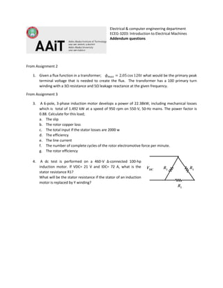
  • 1. Electrical & computer engineering department ECEG-3203: Introduction to Electrical Machines Addendum questions From Assignment 2 1. Given a flux function in a transformer; what would be the primary peak terminal voltage that is needed to create the flux. The transformer has a 100 primary turn winding with a 3Ω resistance and 5Ω leakage reactance at the given frequency. From Assignment 3 3. A 6-pole, 3-phase induction motor develops a power of 22.38kW, including mechanical losses which is total of 1.492 kW at a speed of 950 rpm on 550-V, 50-Hz mains. The power factor is 0.88. Calculate for this load; a. The slip b. The rotor copper loss c. The total input if the stator losses are 2000 w d. The efficiency e. The line current f. The number of complete cycles of the rotor electromotive force per minute. g. The rotor efficiency 4. A dc test is performed on a 460-V Δ-connected 100-hp induction motor. If VDC= 21 V and IDC= 72 A, what is the stator resistance R1? What will be the stator resistance if the stator of an induction motor is replaced by Y winding?
  • 2. ============================================================================= 1. The open circuit and short circuit tests on 300/600V,50Hz,single phase transformer gave the following results OC test (lv side):300V, 0.8A, 70W SC test (hv side):20V, 12A, 90W; where lv and hv are the low and high voltage respectively. Find the equivalent circuit of the transformer referred to the lv side and also calculate the secondary voltage when delivering 6KW at 0.8 p.f (power factor) lagging. 2. A single-phase, 300 kVA, 11 kV/2.2 kV, 60 Hz transformer has the following equivalent circuit parameters referred to the high-voltage side: Rc(HV) = 57.6 k Ω Req(HV) = 2.784 Ω Xm(HV) = 16.34 k Ω Xeq(HV) = 8.45 Ω i. Determine a. No-load current as a percentage of full-load current. b. No-load power loss (i.e., core loss). c. No-load power factor. d. Full-load copper loss. ii. If the load impedance on the low-voltage side is Zload = 1 6<60°Ω, determine the voltage regulation using the approximate equivalent circuit. 3. A single-phase, 100 kVA, 1000/100 V transformer gave the following test results: Open-circuit test (HV side open): 100 V, 6.0 A, 400 W Short-circuit test: 50 V, 100 A, 1800 W a. Determine the rated voltage and rated current for the high-voltage and low- voltage sides. b. Derive an approximate equivalent circuit referred to the HV side. c. Determine the voltage regulation at full load, 0.6 PF leading. d. Draw the phasor diagram for condition (c). 4. A 480V, 60 Hz, 6-pole, three-phase, delta-connected induction motor has the following parameters: R1=0.461 Ω, R2=0.258 Ω, X1=0.507 Ω, X2=0.309 Ω, Xm=30.74 Ω Rotational losses are 2450W. The motor drives a mechanical load at a speed of 1170 rpm. Calculate the following information: a) Synchronous speed in rpm b) slip c) Line Current d) Input Power e) Airgap Power f) Torque Developed g) Output Power in watts h) Efficiency School of Electrical and Computer Engineering ECEG-3151: Introduction to Electrical Machines Assignment 4 Deadline: 21 January, 2015
  • 3. 5. A 25 HP,400V,50Hz,4 pole, star connected induction motor has the following impedances per phase in ohm referred to the stator side: R1=0.641; R2=0.332; X1=1.106; X2=0.464 and Xmag =26.30 Rotational losses are assumed to be constant and are 1.1KW and core losses are assumed to be of negligible order (Rc be very large).If the slip 2.2% at rated voltage and frequency. Find i. Speed iii.Power factor v.Effiecency of motor ii. Stator current iv.Output and input power 6. A 3 phase, 25 hp, 460 V, 60 Hz, 1760 rpm, wound-rotor induction motor has the following equivalent circuit parameters:R1= 0.25 Ω, X1 = 1.2 Ω, X2’ = 1.1 Ω, R2’= 0.2Ω, Xm = 35 Ω The motor is connected to a 3 phase, 460 V, 60 Hz, supply. a. Determine the number of poles of the machine. b. Determine the starting torque. c. Determine the value of the external resistance required in each phase of the rotor circuit such that the maximum torque occurs at starting. 7. The armature current of a series DC motor is 60 A when on full-load. If the load is adjusted to that this current decreases to 40-A, find the new torque expressed as a percentage of the full-load torque. The flux for a current of 40 A is 70% of that when current is 60 A. 8. A 100-kW, 250-V, 400-A, 1200-r/min dc shunt generator has the magnetization curves (including armature-reaction effects) of Fig. 1. The armature-circuit resistance, including brushes, is 0.025 . The generator is driven at a constant speed of 1200 r/min, and the excitation is adjusted (by varying the shunt-field rheostat) to give rated voltage at no load. (a) Determine the terminal voltage at an armature current of 400 A. (b) A series field of four turns per pole having a resistance of 0.005  is to be added. There are 1000 turns per pole in the shunt field. The generator is to be flat- compounded so that the full-load voltage is 250 V when the shunt-field rheostat is adjusted to give a no-load voltage of 250 V. Show how a resistance across the series field (referred to as a series-field diverter) can be adjusted to produce the desired performance. 9. A dc series motor runs at 500r.p.m on 220V supply drawing a current of 50A.The total resistance of the machine (Ra and Rse) is 0.15 ohm, calculate the value of the extra resistance to be connected in series with the motor circuit that will reduce the speed to 300r.p.m.The load torque being then half of the previous value. Assume flux is proportional to current. 10. A 60 –KVA,220 V, 50Hz, 1- alternator has effective armature resistance of 0.016 ohm and an armature leakage reactance of 0.07 ohm. Compute the voltage induced in the armature when the alternator is delivering rated current at a load power factor of a. Unity b. 0.7 lagging, and c. 0.7 leading.
  • 4. 11. A 1000KVA, 6.6KV, 3-phase star connected synchronous generator has a synchronous reactance of 25 ohm per phase with negligible resistance. It supplies full load current of 0.8 p.f lagging and at rated terminal voltage. Compute the terminal voltage for the same excitation when the generator supplies full load current at 0.8p.f leading. 12. A 3 -phase, 2300 V, 60 Hz, 12-pole, Y-connected synchronous motor has 4.5 ohms per phase synchronous reactance and negligible stator winding resistance. The motor is connected to an infinite bus and draws 250 amperes at 0.8 power factor lagging. Neglect rotational losses. a. Determine the output power. b. Determine the power to which the motor can be loaded slowly without losing synchronism. Determine the torque, stator current, and supply power factor for this condition Fig 1.