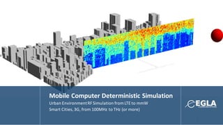
Mobile CDS - mmW / LTE Simulator - Mobile CAD
•
1 like•623 views

Wireless Fading, Simulation and RMS Delay from Cellular to mmW/THz bandwidth

Recommended
Recommended
More Related Content
What's hot
What's hot (20)
Viewers also liked
Viewers also liked (20)
Similar to Mobile CDS - mmW / LTE Simulator - Mobile CAD
Similar to Mobile CDS - mmW / LTE Simulator - Mobile CAD (20)
More from Dr. Edwin Hernandez
More from Dr. Edwin Hernandez (20)
Recently uploaded
Recently uploaded (20)
Mobile CDS - mmW / LTE Simulator - Mobile CAD
- 2. 2 OUR BACKGROUND Mobile CDS or Mobile Computer Deterministic Simulator is an RF Propagation and Simulation Environment that was created after many years of R&D in the areas of electromagnetics and mobile communications. Mobile CDS is a copyright software package created by S.O.L Wireless, LLC and now represented by EGLA COMMUNICATIONS. This tools is the result of several years of R&D conducted by S.O.L Engineers. EGLA COMMUNICATIONS uses Mobile CDS, provides hosting in its cloud environment, and integrates its simulation RF paremeters with MobileCAD. MobileCAD is a wireless emulation patented tool (7231330) that generates LTE / Smart Cities Simulation environments with base stations and mobile phones with RF Characterization created byMobileCDS
- 3. 3 OUR TEAM Salvador Sibecas, Highly innovative with a strong background in RF signal propagation, RF circuits design/testing and digital communications protocols (MAC/PHY layers). Hold twenty-seven issued patents and several other applications have been submitted to the USPTO. Worked at Motorola and Blackberry/RIM Dr. Edwin Hernandez, Owner at EGLA COMMUNICATIONS with patents in wireless simulation and emulation licensed by major mobile phone manufacturers and 10 issued patents worked for Microsoft and Motorola, PhD in Computer Enginieering Rafael Reyes. Electrical engineer with MS in Comp Science with broad experience in government projects, Motorola and Blackberry in wireless systems.
- 4. 4 TABLE OF CONTENTS q Introductionto Mobile-CDS q Tool components diagram q Computational engine description q Protocols Toolbox q 3D databases Toolbox q Material properties q Antenna toolbox q Analysis/post-processingtoolbox. q Simulation results. o LTE data rate analysis. o mmW / Radar Analysis
- 5. 5 INTRODUCTION Mobile-CDS is a 3D deterministic propagation tool with unlimited potential in areas such as; RF characterization of specific regions, wireless protocol evaluation and military applications. Its internal engine is based on ray-tracing technology and the code is fully parallelized. From the comfort of his or her office, using Mobile-CDS the wireless system engineer is able to change several simulation parameters (i.e., the TX and RX antenna height and gain patterns, the carrier frequency, material properties, propagation environment, etc.) and determine their impact on the received signal. Product design cycle time is greatly reduced and money is saved by avoiding expensive and time consuming field data collection campaigns. Field data is only gathered at the end of the design cycle for verification purposes. During the next hour detailed characteristics of the tool and some of its capabilities will be presented. We hope that during this time you all enjoy the presentation and if there are questions, feel free to ask. INTRODUCTION mobile CDS
- 6. Mobile CDS – The Software Software and Source Code in C/C++ - Visual Studio Ray Tracing and Simulation Models. 6 -PTX 1 watt (+30 dBm) -Fc 5.0 GHz -TX ants. Half-wave dipole -HTXd 0.75 meters (on the roof of the vehicle) -RX ant. Half wave dipole -HRX 0.5 meters -Area Outdoor/indoor PRX (dBm)
- 7. Features 7 q Simple to use GUI supporting the following functionalities: Ø Protocol generation. Ø 3D databases (importing, exporting, cloning, cropping, etc.). Ø Propagation analysis (received power, delay spread, co-channel, etc.). Ø Computational engine settings. Ø Materialmedia library. Ø Graphics. q Algorithms supporting LOS (line of site) reflection and transmissions and diffraction propagating modes are build in the original code. Geometrical optics is used to approximate the reflected and transmitted fields. UTD is used to estimate the over the roof and side walls diffracted fields. q In addition to the original facet format, the tool is able to handle other 3D databases formats such as .kml. Both, flat and undulated terrains can be incorporated into the analysis as well as any objects like building, trees and vehicles. q No limitation on the type of environment used in the simulation; urban, suburban or rural. q Able to incorporate in the analysis complex antenna patterns represented by their Eq and Efcomponents. The antenna patterns can be generatedusing an electromagneticsolver (XFDTD), anechoic chamber measurements or data provided by a vendor. q Throughout the ray-tracing process, the program tracks both the magnitude and the phase of the electromagnetic wave. Complex reflection and transmission coefficients are computed at each incident point. This feature allows the system engineer to analyzed not only SISO (single input single output) but also any diversity scheme and MIMO (multiple input multiple output) channels.
- 8. 8 Simulation of LTE and Smart Cities 3G/4G LTE ad 4G are used in modern communication systems for mobile devices in cities and towns around the globle. 3G – 5G uses high frequencies rangingin 500 MHz to 5 GHz. MobileCDS is capable of simulating LTE/iOT Systems and we present a use case with LTE
- 9. 9 Simulation of Multi-millimiter Wave / Radar mmW is used in modern communication systems for RF Backhaul for Multi-Gigabit links as well as characterization ofimages both in civil as militaryapplications. mmW uses ultra-high frequencies rangingin 10’s to 100’s of GHz. The advantage of millimeter wave radiation is that, in addition to clear weather day and night operation, it can also be used in low visibility conditions such as in smoke, fog, clouds and even sandstorms. In this way, millimeter wave imaging expands our vision bylettingus “see” things under poor visibilitycondition MobileCDS is capable of ultra-high frequency simulation and we will present a use case at 6 and 28 GHz.
- 11. COMPUTATIONAL ENGINE The computational window is used to initialize some of the propagation parameters needed to run the program. These include: o The number of transmitted wavefronts. o The number of bounces before a wavefront is terminated. o The propagation modes (LOS, reflection and transmissions and diffraction). o Outdoors only (faster) or both outdoor and indoor. Computation Engine
- 12. Mobile-CDS includes a state of the art 3D databases toolbox. It allows the user to perform the following operations: o Import 3D databases in one of the following formats; Facet, KML and TIN. o Combine terrain and 3D objects (buildings, vehicles, trees, etc.). o Crop a section of the 3D databases. o Assign different electrical properties to different objects included in the databases. o Delete specific objects. o Duplicate databases 3D Databases
- 13. Cars Included 3D Databases : KML, Facet, TIN Selected Buildings Loading Urban Terrains and Buildingsfor RF/mmW Simulations
- 14. Propagation in 3D Database 14 Vehicles on the street Propagating rays
- 17. Importedhead and hand measurements at 1.8 GHz Ideal half-wave dipole Antenna Toolbox
- 18. Antenna Toolbox Mobile-CDS uses 3D antenna patterns in all of its simulations. The patterns are specified in term of their complex Eqand Efelectric field components. This allows the program to track both, the magnitude and the phase of the signal as it propagates through the environment. Patterns generated by antenna manufacturers, measured in an anechoic chamber or generated using an electromagnetic solver such as XFDTD, can easily by converted into .ant format and use in the simulation in order to produce more accurate results.18.0 dBi TX antenna pattern. Both, TX and RX patterns are represented by their complex Etheta and Ephi electric fields components.
- 19. Analysis and Post Processing Mobile-CDS includes an analysis engine, which allow it to carry out several post-processing functions on the simulation data generated. These are just a few: o RF coverage. o RMS-Delay estimates. o Throughput calculations. o Interference analysis. In addition, the program outputs the results in an enhanced file format, which allows the system engineer to post-process the data using one of several scripting languages such as Matlab or Python. Receivers Along High Resolution Linear Path Receivers On Horizontal Plane
- 21. Parameter Value Wireless Protocol LTE TX frequency (MHz) 2110 TX total average power (dBm) 44.8 Htx (meters) 15 TX antenna pattern 18.0 dBi, 4-sectorS 60 degrees pattern TX Losses 6.0 dB Hrx (meters) 2.0 RX antenna pattern Ideal half-wave dipole RX antenna efficiency (%) 50 Diversity gain (dB) 3 Propagation Environment Heavily populated urban LTE Throughput Simulation Parameters Note: The simulation is representative of the coverage generated by a single base station. Co-Channel interference is not included in the simulation results.Receivers On Horizontal Plane 3D Buildings LTE Protocol Specifications LTE Simulation Sample
- 24. 64-QAM 16-QAM QPSK Sector 221 Sector 220 Sector 218 Sector 216 LTE SIMULATION RESULTS (DATA RATE ANALYSIS)
- 25. Parameter Value TX Signal Sinusoid TX frequency (MHz) 2110 TX average power (dBm) 0 Htx (meters) 2000 TX antenna pattern 18.0 dBi, 1-sector 60 degrees pattern TX antenna vertical tilt (deg) 45 Hrx (meters) 2000 RX antenna pattern 18.0 dBi, 1-sector 60 degrees pattern RX antenna vertical tilt (deg) 45 Propagation Environment Outdoor, heavily populated urban Speed (mph) 200 25 Radar Simulation Parameters TX Antenna ReceiversFigure 13 MONO-STATIC RADAR SIMULATION RESULTS
- 26. Parameter Value Delay Spread (ns) 1185.0 Coherence BW (MHz) 0.84 Doppler Spread (Hz) 98 Coherence Time (ms) 10.3 26 Radar Simulation Parameters Note: Results in the Value column represent the 50%. MONO-STATIC RADAR SIMULATION RESULTS
- 27. 27 3D Buildings Databases Isotropic Antenna Highly Directional Antenna Simulation Results Parameter Value TX antenna heights (meters) 5, 40 and 100 Carrier frequencies (GHz) 0.9, 6.0 and 28.0 TX antenna Isotropic RX antenna height (meters) 1.7 RX antenna Isotropic Propagation environment Highly populated urban Propagation mode Outdoor only Computationalmodes LOS, reflections and diffractions Analysis type Path loss and delay spread Coverage region radius (meters) 800 Propagation model Deterministic TX direction Downlink Simulation Parameters Values. PATH LOSS RMS DELAY
- 33. CONCLUDING REMARKS We believe the material presented would have an impact in your product design cycle. The simulations included gives an indication of just some of the capabilities available in Mobile-CDS. The power of the tool is greatly enhanced by post-processing the data stored in an extended file format made available to the system engineer after each run. Complex studies of diversity schemes (switch, time, frequency, gain, MRC), MIMO channels and generation of empirical models for specific environments are readily available. Additionally, MobileCDS is suitable for testing at high GHz bands or even THz depending on computing power, memory, and level of detail required. However, it should be emphasize the capability this state of the art program has to lower production cycle time and cost by avoiding costly and time consuming data collection in the field.
- 35. Our Emulator enables • Load results from MobileCDS • Software reference for the MobileCADPlatform using 2G/UMTS/3G/4G • Software reference for the Mobile IP Proxy protocol implemented using Mobile IP • Test cases and reference implementation using Wi-Fi for emulation • Implementation efforts for 3 nodes with several sectors and multiple devices for emulation • Support and license to software tools and algorithms The fastest way to test your mobile devices and location-based handover! Simulation to Emulation 35
- 36. Emulation Process 36 ! • Covers a system with the EPC (Core Network) and faders • Changes to AWGN, RSSI, BER, others • Playback from a storage medium (File) • Automated Testing (Controller) RSSI Drive Test: -120dBm To -60dBm !
- 37. Emulation Process 37 • Emulation of software and infrastructure in 3G/4G Systems and any packet-based communications network • Drive Test performance characterization • Validation of Media streaming • Validation of Inter-RAT Handovers and UE Performance • Testing mobile phone firmware
- 38. CONCLUDING REMARKS MobileCAD and MobileCDS can work in conjunction and used to simulate many scenarios by creating a simulation environment and regenerating it into a real emulated scenario. Design in LTE/Radar networks can be quickly emulated using both tools and technologies. Again, we appreciate the time taken by those of you present
- 39. Patent Portfolio Already Licensed by some phone manufacturers 3 Issued Utilities: #7,231,330 #7,697,508 #8,213,417 Priority Date: All on July 31, 2003 2 Issued Utility: # 9,071,957 # 9,338,629 Pending Utility: WO 2015/054501 Provisionals: July 27, 2012 Feb 25, 2013 Oct 9, 2013 Apr 28, 2015 1 Provisional: Dec 18, 2014 39
- 40. Licensing Opportunities 40 • Software and patents available for licensing • Exclusive or non-Exclusive Rights • Collaboration and technical assistance available • Software as a Service – Cloud-based Access to Simulation Instances • Integration to existing platforms with our experts