SlideShare a Scribd company logo
1 of 6
Download to read offline
International Journal of Engineering Inventions
e-ISSN: 2278-7461, p-ISSN: 2319-6491
Volume 2, Issue 11 (July 2013) PP: 32-37
www.ijeijournal.com Page | 32
Designing Of Time and Power Efficient Model for Controlling Of
Critical Process
T. Menaka1
, S. Vanila2
, F. Agi Lydia Prizzi3
1
M.E Control & Instrumentation SRM Valliammai Engineering College, Kattankulathur
2
Asst. prof (S.G) SRM Valliammai Engineering College, Kattankulathur
3
Asst. prof (O.G) SRM Valliammai Engineering College, Kattankulathur
Abstract: Over the recent years, time analysis and power efficient has become a desirable property in many
critical processes of the industries like chemical industry, petrochemical industry etc. in the time analysis
concept, we deal about priorities for critical and noncritical parameters based upon time scheduling and
controlling the parameters under the pre-set values stipulated for the processes example: even a low priority
parameter is given the highest priority some time due to drastic change in the outputs value against the set point.
Power efficient factor allows us to lower the power consumption of the instruments for continuous operation. In
this paper, we have used many critical parameters namely temperature sensor, level sensor, current sensor,
viscosity sensor, pressure sensor for time-analysis, controlling and as an input for the serial interface protocol.
Here power efficient is calculated using three different serial interface protocols namely I2
C, UART, and SPI
between two microcontrollers
Index Terms: digital serial interface; embedded systems; power efficiency; time analysis
I. INTRODUCION
Power minimization is an important design criteria for embedded system used in many applications
because due to less power consumed by the instruments, it’s life time increase and energy minimizes .Here we
have evaluated the most power efficient serial protocol by comparing the three different protocols namely
UART,SPI and I2C which are interfaced between two microcontroller . The power efficient is calculated based
upon on the rate of Data been transmitted. The serial interface protocol has been used instead of parallel protocol
because of following advantages that are serial interface uses only one input and output pin for the data transfers
but parallel protocol needs eight or more pins, serial interface supports all kind of embedded peripheral but not
parallel protocol and others. The time analysis concept is based on time scheduling of critical and non -critical
parameter and controlling the values of the parameter against the stipulated set points. The controlling of the
parameters is done with the help of microcontroller.
II. SERIAL INTERFACES
A.UART
The interfaces based on universal asynchronous receivers/transmitters (UART) are often used for
implementing such standards as electronic industries alliance (EIA) recommended standards RS-232, RS-422
and RS-485. UART are nowadays one of the most commonly used methods for communication between an
embedded system and an external device. UARTs provide full-duplex asynchronous serial peer-to-peer
communication. The data transmission over UART usually starts with a start bit(s), that alerts the receiver that a
word of data is about to be sent and allows the receiver to synchronize clocks with the transmitter. After the
start-bit, the actual data is transmitted starting with the least-significant bit. Once a data word has been sent,
transmitter may issue the parity bit (PR) to provide a simple error checking and/or a stop bit (p) to signalize the
end of data word transmission in fig 1.
Fig1. UART INTERFACE
Designing Of Time and Power Efficient Model for Controlling Of Critical Process
www.ijeijournal.com Page | 33
b. SPI
The serial peripheral interface (SPI) that has been popularized by Motorola is a synchronous serial
interface that operates in full duplex mode the typical method for connecting several SPI slave devices to a
master is presented in fig. 2. As the figure re shows, SPI bus utilizes three common lines for all slave devices:
clock (SCLK); master output, slave input (MOSI); master input, slave output (MISO); and a separate chip select
(CS) line for each slave device. Therefore, before starting the communication, the SPI master device pulls down
CS line of the required slave device to select it in The SPI specification does not define neither any maximum
data rate nor any particular addressing scheme or acknowledgment mechanism
Fig 2. SPI INTERFACE
c. I2
C
The developed by Philips inter-integrated circuit (I2
C) interface and its data format are presented in fig.
3 as this figure reveals, the i2c interface uses two common physical lines for clock (SCLK) and data (SDA),
which are pulled-up with resistors (Rp). The I2C interface supports multiple slave and master devices; therefore,
the master device starts the communication by sending the start bit(s) and the device address. Together with the
slave device’s address, the master transmits the 1-bit read/write (r/w) for defining the communication direction,
which would be used until the stop bit (p) closes the current session. The i2c communication protocol
implements per-byte acknowledgments (a/a). the standardized data rates for i2c devices are 10 k-bit/s, 100kbit/s
and 400 k-bit/s, although most recent i2c revision also supports the rates of 1 m-bit/s and 3.4 m-bit/s.
Fig3. I2
C
III. CRITICAL PARAMETER
A.Temperature sensor
The LM35 series are precision integrated-circuit temperature sensors, whose output voltage is linearly
proportional to the Celsius (centigrade) temperature .the LM35 thus has an advantage over linear temperature
sensors calibrated in ° kelvin, as the user is not required to subtract a large constant voltage from its output to
obtain convenient centigrade scaling in fig.4
Fig 4. Temperature sensor
Designing Of Time and Power Efficient Model for Controlling Of Critical Process
www.ijeijournal.com Page | 34
The lm35 does not require any external calibration or trimming to provide typical accuracies of ±1⁄4°c
at room temperature and ±3⁄4° cover a full −55 to+150°temperature range. It can be used with single power
supplies.
B. PRESSURE SENSOR
The sensor used in my project is hand pressure /force/ touch sensor . Pressure is an expression of the
force required to stop a fluid from expanding, and is usually stated in terms of force per unit area. Pressure, P, is
defined as force, F, per unit area, A:
P = F/A
When external force is applied onto the sensor, the resistive element is deformed against the substrate.
Air from the spacer opening is pushed through the air vent in the tail, and the conductive material on the
substrate comes into contact with parts of the active area. The more of the active area that touches the conductive
element, the lower the resistance. All FSRs exhibit a “switch like response”, meaning some amount of force is
necessary to break the sensor's resistance at rest and push it into the measurement range. It can be used to
provide a 0-5vdc output that is proportional to the amount of force applied in it.
Fig 4. Pressure sensor
C. IR TRANSMITTER AND RECEIVER SENSOR
An IR transmitter and receiver is a device that can both emit and receive infrared signals. This sensor
consists of LED, Variable resistor IR photodiode, LM 358 IC and resistor. The infra-red rays ranges from 30 to
250 kHz.This kit transmits a 38 KHz modulated IR signal to a distance of 6 to 8 feet.
Fig 5 I.R sensor Diagram
Place the transmitter on one side and the receiver on the other side to see if an object passes through.
When any obstacle in between during the transmission of the IR radiation, the radiation gets deviated. The
amount of IR radiation which gets deviated is received by the receiver. From the deviations, we can come to
know the distances at which the obstacle is present and how much of the rays have been deviated.
In this project, IR sensor is present in the master microcontroller. As soon as the obstacle comes in front of IR
rays, the LCD of the master microcontroller displays that “IR DETECTED”. The same sentence format is
transmitted to slave microcontroller’s LCD display. It can be also used as a remote switch to turn objects OFF
and ON by infrared radiations.
IV. EXPERIMENTAL SETUP
For evaluating the power consumption for I2C, SPI and UART interfaces in real-life conditions we
have used the test-bed build around two pick it 3 development boards from microchip with pic16F788A
microcontrollers on-board.The microcontroller of the first board was programmed to transmit the data over the
Designing Of Time and Power Efficient Model for Controlling Of Critical Process
www.ijeijournal.com Page | 35
serial interface, while the microcontroller of the second board was used to receive the data. the pins of the
microcontrollers that were required for implementing the serial interfaces have been connected together using 10
cm long wires in fig.9.the input values were of various parameters which are critically important including
temperature, pressure and IR sensor etc. For evaluating the power consumptions for I2
C, SPI and UART in real
time conditions, we used PIC16F877A microcontroller on board .In the first (TX) board of the microcontroller,
known as master was programed to transmit the data and the second board (RX) i.e. slave was used to receive
the data.
FIG 9. Experimental setup
For both the transmitting and receiving of the data, all the three protocol have been used. The digitally
converted data received from various sensors through ADC is transmitted to slave microcontroller and the
analog values are displayed in the LCD
The power consumption measurement was done in three stages. First of all, power consumption for
TX and RX boards were measured when the serial interfaces on both boards were initialized, but no transmission
was on-going. The second measurements were made when the transmission was on- going: during the second
measurement the RX board was selected as data target, during the third measurement - RX board was not
selected as target .The power consumption during the second and third stages was measured for two cases: single
byte transmission and transmission of eight data bytes in single packet. This is how the power efficient was
calculated in real time in my project with the help of suitable hardware kit.
For time analysis, different type of sensors are used in which prioritises are given depending upon
process been done at that point of time .But sometimes even a low priority parameter is given the highest priority
some time due to drastic change in the outputs value against the set point value. The output of the sensors is in
the analog form which has to convert into a digital form. For the conversion, we use analog to digital converter.
The digitalized output is sent to the microcontroller for controlling each and every parameter in case of large
variation in the parameter value or sends the data as an input for serial protocol.
V. RESULTS
A.SIMULATION RESULT
1. UART AND I2
C
Designing Of Time and Power Efficient Model for Controlling Of Critical Process
www.ijeijournal.com Page | 36
2.SPI
B. HARDWARE RESULT
This is result is for 1 bytes and 8 bytes datum
1. Pressure sensor
CURRENT RATING POWER CONSUMED
I2
C SPI UART I2
C SPI UART
A A A mV mV mV
0.08 0.09 0.10 0.4 0.45 0.5
0.12 0.14 0.15 0.6 0.7 0.75
2. I.R SENSOR
CURRENT RATING POWER CONSUMED
I2
C SPI UART I2
C SPI UART
A A A mV mV mV
0.09 0.12 0.13 0.45 0.6 0.65
0.16 0.17 0.18 0.8 0.85 0.9
3. TEMPERATURE SENSOR
CURRENT RATING POWER CONSUMED
I2
C SPI UART I2
C SPI UART
A A A mV mV mV
0.07 0.09 0.11 0.35 0.45 0.55
0.13 0.14 0.16 0.65 0.7 0.8
VI. DISCUSSION AND CONCLUSION
We have discussed and evaluated the most digital serial interfacing protocols that are to be used by
different embedded systems namely SPI, UART and I2
C . Ideally among all three interfaces used here , I2
C had
the lowest power consumption during data exchanges for the same data rate .
The interface based on UART consumed 22 to 23 % more power for transferring the same amount of
data compare to I2
C. However, using SPI interface consumed more than 2 times more energy comparing to I2
C at
single byte transmission and for packet over 8 bytes so it rated as more efficient than UART.
Although the implementation of the serial interface in software requires same amount of resource as
implementation in hardware .In our experiment, we used only one hardware platform that is PIC microcontroller
with assumption that the result can be expanded to the same extent for other platform of hardwares. In our
project, we evaluated the serial interface for one particular data rate and estimated that maximum data rates can
be achieved at next implementation stage.
Additionally, we explored the way and means for time-scheduling of the data of critical parameter.
Nevertheless, all the three protocols used here are having certain advantages over each other, for the
transmission of data pretending to the critical parameters I2
C is rated to be the most ideally one.
Designing Of Time and Power Efficient Model for Controlling Of Critical Process
www.ijeijournal.com Page | 37
References
[1] D. Johnson, “Implementing serial bus interfaces using general purpose digital instrumentation,” IEEEInstrumentation
Measurement Magazine,vol. 13, no. 4, pp. 8 –13, August 2010
[2] M. Dewey and D. Johnson, “Applying High Performance Digital Instrumentation for Video Test Applications”, in Proc. IEEE
AUTOTESTCON 2008, 2008
[3] “Serial Peripheral Interface Bus”, Wikipedia, [Online] Available:http://en.wikipedia.org/wiki/Serial_Peripheral_Interface_BUS
[4] “I2C”, Wikipedia, [Online] Available: http://en.wikipedia.org/wiki/I2c.
[5] “Joint Test Action Group”, Wikipedia, [Online] Available: http://en.wikipedia.org/wiki/JTAG
[6] SPI Block Guide v. 03.06, Motorola Semiconductor Products Inc. Std.S12SPIV3/D, 2003.
[7] I2C - bus specification and user manual rev.03, NXP Semiconductors Std. UM10 204, 2007.

More Related Content

What's hot

RESUME__SUMER SAILI
RESUME__SUMER SAILIRESUME__SUMER SAILI
RESUME__SUMER SAILI
Sumer Saili
 
RAJPRASAD PAPER NO-127
RAJPRASAD PAPER NO-127RAJPRASAD PAPER NO-127
RAJPRASAD PAPER NO-127
RAJPRASAD RS
 

What's hot (17)

E033021025
E033021025E033021025
E033021025
 
510 277-283
510 277-283510 277-283
510 277-283
 
IRJET- Transformer Monitoring and Protection System using AVR Atmega16 Mi...
IRJET-  	  Transformer Monitoring and Protection System using AVR Atmega16 Mi...IRJET-  	  Transformer Monitoring and Protection System using AVR Atmega16 Mi...
IRJET- Transformer Monitoring and Protection System using AVR Atmega16 Mi...
 
D041121722
D041121722D041121722
D041121722
 
Ups battery monitoring system over gsm by humayun kobir
Ups battery monitoring system over gsm by humayun kobirUps battery monitoring system over gsm by humayun kobir
Ups battery monitoring system over gsm by humayun kobir
 
Design and Implementation of Low Power 3-Bit Flash ADC Using 180nm CMOS Techn...
Design and Implementation of Low Power 3-Bit Flash ADC Using 180nm CMOS Techn...Design and Implementation of Low Power 3-Bit Flash ADC Using 180nm CMOS Techn...
Design and Implementation of Low Power 3-Bit Flash ADC Using 180nm CMOS Techn...
 
Implementation of the can bus in the vehicle based on arm 7
Implementation of the can bus in the vehicle based on arm 7Implementation of the can bus in the vehicle based on arm 7
Implementation of the can bus in the vehicle based on arm 7
 
Mobile robotic platform to gathering real time sensory data in wireless perso...
Mobile robotic platform to gathering real time sensory data in wireless perso...Mobile robotic platform to gathering real time sensory data in wireless perso...
Mobile robotic platform to gathering real time sensory data in wireless perso...
 
Implementation of an Improved Microcontroller Based Moving Message Display Sy...
Implementation of an Improved Microcontroller Based Moving Message Display Sy...Implementation of an Improved Microcontroller Based Moving Message Display Sy...
Implementation of an Improved Microcontroller Based Moving Message Display Sy...
 
DESIGN AND DEVELOPMENT OF A LOW-COST MICROCONTROLLER BASED SINGLE PHASE WATER...
DESIGN AND DEVELOPMENT OF A LOW-COST MICROCONTROLLER BASED SINGLE PHASE WATER...DESIGN AND DEVELOPMENT OF A LOW-COST MICROCONTROLLER BASED SINGLE PHASE WATER...
DESIGN AND DEVELOPMENT OF A LOW-COST MICROCONTROLLER BASED SINGLE PHASE WATER...
 
Network Based Data Acquisition and Logging System using PIC Microcontroller
Network Based Data Acquisition and Logging System using PIC MicrocontrollerNetwork Based Data Acquisition and Logging System using PIC Microcontroller
Network Based Data Acquisition and Logging System using PIC Microcontroller
 
RESUME__SUMER SAILI
RESUME__SUMER SAILIRESUME__SUMER SAILI
RESUME__SUMER SAILI
 
RAJPRASAD PAPER NO-127
RAJPRASAD PAPER NO-127RAJPRASAD PAPER NO-127
RAJPRASAD PAPER NO-127
 
International Journal of Computational Engineering Research(IJCER)
International Journal of Computational Engineering Research(IJCER)International Journal of Computational Engineering Research(IJCER)
International Journal of Computational Engineering Research(IJCER)
 
Fpga based heart rate monitoring system using gsm
Fpga based heart rate monitoring system using gsmFpga based heart rate monitoring system using gsm
Fpga based heart rate monitoring system using gsm
 
Zigbee based parameter monitoring and controlling system for induction machine
Zigbee based parameter monitoring and controlling system for induction machineZigbee based parameter monitoring and controlling system for induction machine
Zigbee based parameter monitoring and controlling system for induction machine
 
Application of Microcontroller in Transmitter Section of Wireless System
Application of Microcontroller in Transmitter Section of Wireless SystemApplication of Microcontroller in Transmitter Section of Wireless System
Application of Microcontroller in Transmitter Section of Wireless System
 

Viewers also liked (8)

ADAWY CV 2015
ADAWY CV 2015ADAWY CV 2015
ADAWY CV 2015
 
A04120105
A04120105A04120105
A04120105
 
B04120610
B04120610B04120610
B04120610
 
E04122330
E04122330E04122330
E04122330
 
G04123844
G04123844G04123844
G04123844
 
F04123137
F04123137F04123137
F04123137
 
C04121115
C04121115C04121115
C04121115
 
H04124548
H04124548H04124548
H04124548
 

Similar to Designing Of Time and Power Efficient Model for Controlling Of Critical Process

A remote monitoring system for a three phase 10-kva switchable distribution t...
A remote monitoring system for a three phase 10-kva switchable distribution t...A remote monitoring system for a three phase 10-kva switchable distribution t...
A remote monitoring system for a three phase 10-kva switchable distribution t...
eSAT Journals
 

Similar to Designing Of Time and Power Efficient Model for Controlling Of Critical Process (20)

B41012015
B41012015B41012015
B41012015
 
TRANSFORMER FAULT DETECTION AND MONITORING
TRANSFORMER FAULT DETECTION AND MONITORINGTRANSFORMER FAULT DETECTION AND MONITORING
TRANSFORMER FAULT DETECTION AND MONITORING
 
Real-Time Monitoring and Control System for Industry
Real-Time Monitoring and Control System for IndustryReal-Time Monitoring and Control System for Industry
Real-Time Monitoring and Control System for Industry
 
Design and development of programmable controller for air sampling machine
Design and development of programmable controller for air sampling machineDesign and development of programmable controller for air sampling machine
Design and development of programmable controller for air sampling machine
 
Industrial Process Management Using LabVIEW
Industrial Process Management Using LabVIEWIndustrial Process Management Using LabVIEW
Industrial Process Management Using LabVIEW
 
Industrial Process Management Using LabVIEW
Industrial Process Management Using LabVIEWIndustrial Process Management Using LabVIEW
Industrial Process Management Using LabVIEW
 
Design and Implementation of Low Cost Smart Web Sensors for Electric Power Qu...
Design and Implementation of Low Cost Smart Web Sensors for Electric Power Qu...Design and Implementation of Low Cost Smart Web Sensors for Electric Power Qu...
Design and Implementation of Low Cost Smart Web Sensors for Electric Power Qu...
 
IRJET- Solar Powered Transmission Line Inspection Robot
IRJET- Solar Powered Transmission Line Inspection RobotIRJET- Solar Powered Transmission Line Inspection Robot
IRJET- Solar Powered Transmission Line Inspection Robot
 
Implementation of an Improved Microcontroller Based Moving Message Display Sy...
Implementation of an Improved Microcontroller Based Moving Message Display Sy...Implementation of an Improved Microcontroller Based Moving Message Display Sy...
Implementation of an Improved Microcontroller Based Moving Message Display Sy...
 
Implementation of an Improved Microcontroller Based Moving Message Display Sy...
Implementation of an Improved Microcontroller Based Moving Message Display Sy...Implementation of an Improved Microcontroller Based Moving Message Display Sy...
Implementation of an Improved Microcontroller Based Moving Message Display Sy...
 
E010132736
E010132736E010132736
E010132736
 
IRJET- Monitoring and Protection of Distribution Transformer using GSM Module
IRJET- Monitoring and Protection of Distribution Transformer using GSM ModuleIRJET- Monitoring and Protection of Distribution Transformer using GSM Module
IRJET- Monitoring and Protection of Distribution Transformer using GSM Module
 
IRJET - Monitoring and Protection of Distribution Transformer using GSM Module
IRJET - Monitoring and Protection of Distribution Transformer using GSM ModuleIRJET - Monitoring and Protection of Distribution Transformer using GSM Module
IRJET - Monitoring and Protection of Distribution Transformer using GSM Module
 
IRJET- Data Acquisition using Tensile Strength Testing Machine
IRJET- Data Acquisition using Tensile Strength Testing MachineIRJET- Data Acquisition using Tensile Strength Testing Machine
IRJET- Data Acquisition using Tensile Strength Testing Machine
 
A remote monitoring system for a three phase 10-kva switchable distribution t...
A remote monitoring system for a three phase 10-kva switchable distribution t...A remote monitoring system for a three phase 10-kva switchable distribution t...
A remote monitoring system for a three phase 10-kva switchable distribution t...
 
A remote monitoring system for a three phase 10-kva switchable distribution t...
A remote monitoring system for a three phase 10-kva switchable distribution t...A remote monitoring system for a three phase 10-kva switchable distribution t...
A remote monitoring system for a three phase 10-kva switchable distribution t...
 
A010610109
A010610109A010610109
A010610109
 
Development of Distributed Mains Monitoring and Switching System for Indus Co...
Development of Distributed Mains Monitoring and Switching System for Indus Co...Development of Distributed Mains Monitoring and Switching System for Indus Co...
Development of Distributed Mains Monitoring and Switching System for Indus Co...
 
Designing and Controlling of Motor by Interfacing RS232 with Microcontroller
Designing and Controlling of Motor by Interfacing RS232 with MicrocontrollerDesigning and Controlling of Motor by Interfacing RS232 with Microcontroller
Designing and Controlling of Motor by Interfacing RS232 with Microcontroller
 

More from International Journal of Engineering Inventions www.ijeijournal.com

More from International Journal of Engineering Inventions www.ijeijournal.com (20)

F04113640
F04113640F04113640
F04113640
 
E04112135
E04112135E04112135
E04112135
 
D04111520
D04111520D04111520
D04111520
 
C04111114
C04111114C04111114
C04111114
 
B04110710
B04110710B04110710
B04110710
 
A04110106
A04110106A04110106
A04110106
 
I04105358
I04105358I04105358
I04105358
 
H04104952
H04104952H04104952
H04104952
 
G04103948
G04103948G04103948
G04103948
 
F04103138
F04103138F04103138
F04103138
 
E04102330
E04102330E04102330
E04102330
 
D04101822
D04101822D04101822
D04101822
 
C04101217
C04101217C04101217
C04101217
 
B04100611
B04100611B04100611
B04100611
 
A04100105
A04100105A04100105
A04100105
 
D0494146
D0494146D0494146
D0494146
 
C0491740
C0491740C0491740
C0491740
 
B0490716
B0490716B0490716
B0490716
 
A0490106
A0490106A0490106
A0490106
 
F0483340
F0483340F0483340
F0483340
 

Recently uploaded

Histor y of HAM Radio presentation slide
Histor y of HAM Radio presentation slideHistor y of HAM Radio presentation slide
Histor y of HAM Radio presentation slide
vu2urc
 
+971581248768>> SAFE AND ORIGINAL ABORTION PILLS FOR SALE IN DUBAI AND ABUDHA...
+971581248768>> SAFE AND ORIGINAL ABORTION PILLS FOR SALE IN DUBAI AND ABUDHA...+971581248768>> SAFE AND ORIGINAL ABORTION PILLS FOR SALE IN DUBAI AND ABUDHA...
+971581248768>> SAFE AND ORIGINAL ABORTION PILLS FOR SALE IN DUBAI AND ABUDHA...
?#DUbAI#??##{{(☎️+971_581248768%)**%*]'#abortion pills for sale in dubai@
 

Recently uploaded (20)

GenAI Risks & Security Meetup 01052024.pdf
GenAI Risks & Security Meetup 01052024.pdfGenAI Risks & Security Meetup 01052024.pdf
GenAI Risks & Security Meetup 01052024.pdf
 
How to Troubleshoot Apps for the Modern Connected Worker
How to Troubleshoot Apps for the Modern Connected WorkerHow to Troubleshoot Apps for the Modern Connected Worker
How to Troubleshoot Apps for the Modern Connected Worker
 
Advantages of Hiring UIUX Design Service Providers for Your Business
Advantages of Hiring UIUX Design Service Providers for Your BusinessAdvantages of Hiring UIUX Design Service Providers for Your Business
Advantages of Hiring UIUX Design Service Providers for Your Business
 
Axa Assurance Maroc - Insurer Innovation Award 2024
Axa Assurance Maroc - Insurer Innovation Award 2024Axa Assurance Maroc - Insurer Innovation Award 2024
Axa Assurance Maroc - Insurer Innovation Award 2024
 
A Year of the Servo Reboot: Where Are We Now?
A Year of the Servo Reboot: Where Are We Now?A Year of the Servo Reboot: Where Are We Now?
A Year of the Servo Reboot: Where Are We Now?
 
Boost Fertility New Invention Ups Success Rates.pdf
Boost Fertility New Invention Ups Success Rates.pdfBoost Fertility New Invention Ups Success Rates.pdf
Boost Fertility New Invention Ups Success Rates.pdf
 
Apidays New York 2024 - Scaling API-first by Ian Reasor and Radu Cotescu, Adobe
Apidays New York 2024 - Scaling API-first by Ian Reasor and Radu Cotescu, AdobeApidays New York 2024 - Scaling API-first by Ian Reasor and Radu Cotescu, Adobe
Apidays New York 2024 - Scaling API-first by Ian Reasor and Radu Cotescu, Adobe
 
TrustArc Webinar - Stay Ahead of US State Data Privacy Law Developments
TrustArc Webinar - Stay Ahead of US State Data Privacy Law DevelopmentsTrustArc Webinar - Stay Ahead of US State Data Privacy Law Developments
TrustArc Webinar - Stay Ahead of US State Data Privacy Law Developments
 
Histor y of HAM Radio presentation slide
Histor y of HAM Radio presentation slideHistor y of HAM Radio presentation slide
Histor y of HAM Radio presentation slide
 
GenCyber Cyber Security Day Presentation
GenCyber Cyber Security Day PresentationGenCyber Cyber Security Day Presentation
GenCyber Cyber Security Day Presentation
 
Developing An App To Navigate The Roads of Brazil
Developing An App To Navigate The Roads of BrazilDeveloping An App To Navigate The Roads of Brazil
Developing An App To Navigate The Roads of Brazil
 
Scaling API-first – The story of a global engineering organization
Scaling API-first – The story of a global engineering organizationScaling API-first – The story of a global engineering organization
Scaling API-first – The story of a global engineering organization
 
What Are The Drone Anti-jamming Systems Technology?
What Are The Drone Anti-jamming Systems Technology?What Are The Drone Anti-jamming Systems Technology?
What Are The Drone Anti-jamming Systems Technology?
 
Automating Google Workspace (GWS) & more with Apps Script
Automating Google Workspace (GWS) & more with Apps ScriptAutomating Google Workspace (GWS) & more with Apps Script
Automating Google Workspace (GWS) & more with Apps Script
 
The 7 Things I Know About Cyber Security After 25 Years | April 2024
The 7 Things I Know About Cyber Security After 25 Years | April 2024The 7 Things I Know About Cyber Security After 25 Years | April 2024
The 7 Things I Know About Cyber Security After 25 Years | April 2024
 
Workshop - Best of Both Worlds_ Combine KG and Vector search for enhanced R...
Workshop - Best of Both Worlds_ Combine  KG and Vector search for  enhanced R...Workshop - Best of Both Worlds_ Combine  KG and Vector search for  enhanced R...
Workshop - Best of Both Worlds_ Combine KG and Vector search for enhanced R...
 
Driving Behavioral Change for Information Management through Data-Driven Gree...
Driving Behavioral Change for Information Management through Data-Driven Gree...Driving Behavioral Change for Information Management through Data-Driven Gree...
Driving Behavioral Change for Information Management through Data-Driven Gree...
 
+971581248768>> SAFE AND ORIGINAL ABORTION PILLS FOR SALE IN DUBAI AND ABUDHA...
+971581248768>> SAFE AND ORIGINAL ABORTION PILLS FOR SALE IN DUBAI AND ABUDHA...+971581248768>> SAFE AND ORIGINAL ABORTION PILLS FOR SALE IN DUBAI AND ABUDHA...
+971581248768>> SAFE AND ORIGINAL ABORTION PILLS FOR SALE IN DUBAI AND ABUDHA...
 
Mastering MySQL Database Architecture: Deep Dive into MySQL Shell and MySQL R...
Mastering MySQL Database Architecture: Deep Dive into MySQL Shell and MySQL R...Mastering MySQL Database Architecture: Deep Dive into MySQL Shell and MySQL R...
Mastering MySQL Database Architecture: Deep Dive into MySQL Shell and MySQL R...
 
2024: Domino Containers - The Next Step. News from the Domino Container commu...
2024: Domino Containers - The Next Step. News from the Domino Container commu...2024: Domino Containers - The Next Step. News from the Domino Container commu...
2024: Domino Containers - The Next Step. News from the Domino Container commu...
 

Designing Of Time and Power Efficient Model for Controlling Of Critical Process

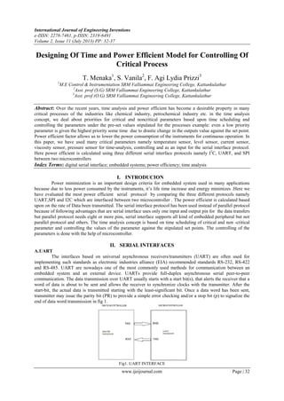
  • 1. International Journal of Engineering Inventions e-ISSN: 2278-7461, p-ISSN: 2319-6491 Volume 2, Issue 11 (July 2013) PP: 32-37 www.ijeijournal.com Page | 32 Designing Of Time and Power Efficient Model for Controlling Of Critical Process T. Menaka1 , S. Vanila2 , F. Agi Lydia Prizzi3 1 M.E Control & Instrumentation SRM Valliammai Engineering College, Kattankulathur 2 Asst. prof (S.G) SRM Valliammai Engineering College, Kattankulathur 3 Asst. prof (O.G) SRM Valliammai Engineering College, Kattankulathur Abstract: Over the recent years, time analysis and power efficient has become a desirable property in many critical processes of the industries like chemical industry, petrochemical industry etc. in the time analysis concept, we deal about priorities for critical and noncritical parameters based upon time scheduling and controlling the parameters under the pre-set values stipulated for the processes example: even a low priority parameter is given the highest priority some time due to drastic change in the outputs value against the set point. Power efficient factor allows us to lower the power consumption of the instruments for continuous operation. In this paper, we have used many critical parameters namely temperature sensor, level sensor, current sensor, viscosity sensor, pressure sensor for time-analysis, controlling and as an input for the serial interface protocol. Here power efficient is calculated using three different serial interface protocols namely I2 C, UART, and SPI between two microcontrollers Index Terms: digital serial interface; embedded systems; power efficiency; time analysis I. INTRODUCION Power minimization is an important design criteria for embedded system used in many applications because due to less power consumed by the instruments, it’s life time increase and energy minimizes .Here we have evaluated the most power efficient serial protocol by comparing the three different protocols namely UART,SPI and I2C which are interfaced between two microcontroller . The power efficient is calculated based upon on the rate of Data been transmitted. The serial interface protocol has been used instead of parallel protocol because of following advantages that are serial interface uses only one input and output pin for the data transfers but parallel protocol needs eight or more pins, serial interface supports all kind of embedded peripheral but not parallel protocol and others. The time analysis concept is based on time scheduling of critical and non -critical parameter and controlling the values of the parameter against the stipulated set points. The controlling of the parameters is done with the help of microcontroller. II. SERIAL INTERFACES A.UART The interfaces based on universal asynchronous receivers/transmitters (UART) are often used for implementing such standards as electronic industries alliance (EIA) recommended standards RS-232, RS-422 and RS-485. UART are nowadays one of the most commonly used methods for communication between an embedded system and an external device. UARTs provide full-duplex asynchronous serial peer-to-peer communication. The data transmission over UART usually starts with a start bit(s), that alerts the receiver that a word of data is about to be sent and allows the receiver to synchronize clocks with the transmitter. After the start-bit, the actual data is transmitted starting with the least-significant bit. Once a data word has been sent, transmitter may issue the parity bit (PR) to provide a simple error checking and/or a stop bit (p) to signalize the end of data word transmission in fig 1. Fig1. UART INTERFACE
  • 2. Designing Of Time and Power Efficient Model for Controlling Of Critical Process www.ijeijournal.com Page | 33 b. SPI The serial peripheral interface (SPI) that has been popularized by Motorola is a synchronous serial interface that operates in full duplex mode the typical method for connecting several SPI slave devices to a master is presented in fig. 2. As the figure re shows, SPI bus utilizes three common lines for all slave devices: clock (SCLK); master output, slave input (MOSI); master input, slave output (MISO); and a separate chip select (CS) line for each slave device. Therefore, before starting the communication, the SPI master device pulls down CS line of the required slave device to select it in The SPI specification does not define neither any maximum data rate nor any particular addressing scheme or acknowledgment mechanism Fig 2. SPI INTERFACE c. I2 C The developed by Philips inter-integrated circuit (I2 C) interface and its data format are presented in fig. 3 as this figure reveals, the i2c interface uses two common physical lines for clock (SCLK) and data (SDA), which are pulled-up with resistors (Rp). The I2C interface supports multiple slave and master devices; therefore, the master device starts the communication by sending the start bit(s) and the device address. Together with the slave device’s address, the master transmits the 1-bit read/write (r/w) for defining the communication direction, which would be used until the stop bit (p) closes the current session. The i2c communication protocol implements per-byte acknowledgments (a/a). the standardized data rates for i2c devices are 10 k-bit/s, 100kbit/s and 400 k-bit/s, although most recent i2c revision also supports the rates of 1 m-bit/s and 3.4 m-bit/s. Fig3. I2 C III. CRITICAL PARAMETER A.Temperature sensor The LM35 series are precision integrated-circuit temperature sensors, whose output voltage is linearly proportional to the Celsius (centigrade) temperature .the LM35 thus has an advantage over linear temperature sensors calibrated in ° kelvin, as the user is not required to subtract a large constant voltage from its output to obtain convenient centigrade scaling in fig.4 Fig 4. Temperature sensor
  • 3. Designing Of Time and Power Efficient Model for Controlling Of Critical Process www.ijeijournal.com Page | 34 The lm35 does not require any external calibration or trimming to provide typical accuracies of ±1⁄4°c at room temperature and ±3⁄4° cover a full −55 to+150°temperature range. It can be used with single power supplies. B. PRESSURE SENSOR The sensor used in my project is hand pressure /force/ touch sensor . Pressure is an expression of the force required to stop a fluid from expanding, and is usually stated in terms of force per unit area. Pressure, P, is defined as force, F, per unit area, A: P = F/A When external force is applied onto the sensor, the resistive element is deformed against the substrate. Air from the spacer opening is pushed through the air vent in the tail, and the conductive material on the substrate comes into contact with parts of the active area. The more of the active area that touches the conductive element, the lower the resistance. All FSRs exhibit a “switch like response”, meaning some amount of force is necessary to break the sensor's resistance at rest and push it into the measurement range. It can be used to provide a 0-5vdc output that is proportional to the amount of force applied in it. Fig 4. Pressure sensor C. IR TRANSMITTER AND RECEIVER SENSOR An IR transmitter and receiver is a device that can both emit and receive infrared signals. This sensor consists of LED, Variable resistor IR photodiode, LM 358 IC and resistor. The infra-red rays ranges from 30 to 250 kHz.This kit transmits a 38 KHz modulated IR signal to a distance of 6 to 8 feet. Fig 5 I.R sensor Diagram Place the transmitter on one side and the receiver on the other side to see if an object passes through. When any obstacle in between during the transmission of the IR radiation, the radiation gets deviated. The amount of IR radiation which gets deviated is received by the receiver. From the deviations, we can come to know the distances at which the obstacle is present and how much of the rays have been deviated. In this project, IR sensor is present in the master microcontroller. As soon as the obstacle comes in front of IR rays, the LCD of the master microcontroller displays that “IR DETECTED”. The same sentence format is transmitted to slave microcontroller’s LCD display. It can be also used as a remote switch to turn objects OFF and ON by infrared radiations. IV. EXPERIMENTAL SETUP For evaluating the power consumption for I2C, SPI and UART interfaces in real-life conditions we have used the test-bed build around two pick it 3 development boards from microchip with pic16F788A microcontrollers on-board.The microcontroller of the first board was programmed to transmit the data over the
  • 4. Designing Of Time and Power Efficient Model for Controlling Of Critical Process www.ijeijournal.com Page | 35 serial interface, while the microcontroller of the second board was used to receive the data. the pins of the microcontrollers that were required for implementing the serial interfaces have been connected together using 10 cm long wires in fig.9.the input values were of various parameters which are critically important including temperature, pressure and IR sensor etc. For evaluating the power consumptions for I2 C, SPI and UART in real time conditions, we used PIC16F877A microcontroller on board .In the first (TX) board of the microcontroller, known as master was programed to transmit the data and the second board (RX) i.e. slave was used to receive the data. FIG 9. Experimental setup For both the transmitting and receiving of the data, all the three protocol have been used. The digitally converted data received from various sensors through ADC is transmitted to slave microcontroller and the analog values are displayed in the LCD The power consumption measurement was done in three stages. First of all, power consumption for TX and RX boards were measured when the serial interfaces on both boards were initialized, but no transmission was on-going. The second measurements were made when the transmission was on- going: during the second measurement the RX board was selected as data target, during the third measurement - RX board was not selected as target .The power consumption during the second and third stages was measured for two cases: single byte transmission and transmission of eight data bytes in single packet. This is how the power efficient was calculated in real time in my project with the help of suitable hardware kit. For time analysis, different type of sensors are used in which prioritises are given depending upon process been done at that point of time .But sometimes even a low priority parameter is given the highest priority some time due to drastic change in the outputs value against the set point value. The output of the sensors is in the analog form which has to convert into a digital form. For the conversion, we use analog to digital converter. The digitalized output is sent to the microcontroller for controlling each and every parameter in case of large variation in the parameter value or sends the data as an input for serial protocol. V. RESULTS A.SIMULATION RESULT 1. UART AND I2 C
  • 5. Designing Of Time and Power Efficient Model for Controlling Of Critical Process www.ijeijournal.com Page | 36 2.SPI B. HARDWARE RESULT This is result is for 1 bytes and 8 bytes datum 1. Pressure sensor CURRENT RATING POWER CONSUMED I2 C SPI UART I2 C SPI UART A A A mV mV mV 0.08 0.09 0.10 0.4 0.45 0.5 0.12 0.14 0.15 0.6 0.7 0.75 2. I.R SENSOR CURRENT RATING POWER CONSUMED I2 C SPI UART I2 C SPI UART A A A mV mV mV 0.09 0.12 0.13 0.45 0.6 0.65 0.16 0.17 0.18 0.8 0.85 0.9 3. TEMPERATURE SENSOR CURRENT RATING POWER CONSUMED I2 C SPI UART I2 C SPI UART A A A mV mV mV 0.07 0.09 0.11 0.35 0.45 0.55 0.13 0.14 0.16 0.65 0.7 0.8 VI. DISCUSSION AND CONCLUSION We have discussed and evaluated the most digital serial interfacing protocols that are to be used by different embedded systems namely SPI, UART and I2 C . Ideally among all three interfaces used here , I2 C had the lowest power consumption during data exchanges for the same data rate . The interface based on UART consumed 22 to 23 % more power for transferring the same amount of data compare to I2 C. However, using SPI interface consumed more than 2 times more energy comparing to I2 C at single byte transmission and for packet over 8 bytes so it rated as more efficient than UART. Although the implementation of the serial interface in software requires same amount of resource as implementation in hardware .In our experiment, we used only one hardware platform that is PIC microcontroller with assumption that the result can be expanded to the same extent for other platform of hardwares. In our project, we evaluated the serial interface for one particular data rate and estimated that maximum data rates can be achieved at next implementation stage. Additionally, we explored the way and means for time-scheduling of the data of critical parameter. Nevertheless, all the three protocols used here are having certain advantages over each other, for the transmission of data pretending to the critical parameters I2 C is rated to be the most ideally one.
  • 6. Designing Of Time and Power Efficient Model for Controlling Of Critical Process www.ijeijournal.com Page | 37 References [1] D. Johnson, “Implementing serial bus interfaces using general purpose digital instrumentation,” IEEEInstrumentation Measurement Magazine,vol. 13, no. 4, pp. 8 –13, August 2010 [2] M. Dewey and D. Johnson, “Applying High Performance Digital Instrumentation for Video Test Applications”, in Proc. IEEE AUTOTESTCON 2008, 2008 [3] “Serial Peripheral Interface Bus”, Wikipedia, [Online] Available:http://en.wikipedia.org/wiki/Serial_Peripheral_Interface_BUS [4] “I2C”, Wikipedia, [Online] Available: http://en.wikipedia.org/wiki/I2c. [5] “Joint Test Action Group”, Wikipedia, [Online] Available: http://en.wikipedia.org/wiki/JTAG [6] SPI Block Guide v. 03.06, Motorola Semiconductor Products Inc. Std.S12SPIV3/D, 2003. [7] I2C - bus specification and user manual rev.03, NXP Semiconductors Std. UM10 204, 2007.