SlideShare ist ein Scribd-Unternehmen logo
1 von 8
Downloaden Sie, um offline zu lesen
International Journal of Engineering Inventions
ISSN: 2278-7461, www.ijeijournal.com
Volume 1, Issue 1(August 2012) PP: 24-31


           Optimization of Process Parameters in Eli-Twist Yarn
                                 P.Mageshkumar1, Dr.T.Ramachandran2
       1
        Assistant Professor, Department of Textile Technology, K.S.Rangasamy College of Technology, Tiruchencode.
                                2
                                  Principal, Karpagam Institute of Technology, Coimbatore.


Abstract––Eli-Twist yarn, produced by Suessen Elite compact spinning technology has superior in technically and
economically in the recent days compared to the two-ply yarns. The quality of this Eli-twist yarn is governed by many
parameters. The distance between roving strands and the negative pressure applied in the suction has substantial
effects on the quality aspect of this yarn. The feed roving distance and negative pressure were varied in such a way
that ten different combinations are produced. The effects of these two parameters on yarns fineness, Rkm, Elongation
%, U %, Hariness were studied. To assess the yarn quality the concept of Cpk (Process Capability Index) could be
used effectively. An attempt has been made to implement the concept of Cpk in the analysis of the properties of Eli-
twist yarn.

Keywords: Eli-Twist, Compact, Hariness, U%, Cpk,

                                              I.          INTRODUCTION
          Eli-Twist is a patented process which produces economically a compact spin-twisted yarn with the EliTe Compact Set
directly on the ring spinning frame. The Eli-Twist Process permits to reduce the twisting triangle to a degree that it has
practically no influence on spinning stability. In this process, two rovings pass through the twin condensers at the entrance of the
drafting system and they are drafted separately at a certain distance. Further the drafted roving leaves the front roller pair of the
drafting system and passes through the compacting zone. In the condensing zone, the distance between the drafted fibre strands
is reduced to about 5 mm by means of two suction slots in V-shaped arrangement in the compacting zone. This close distance is
possible, as the two yarn components when leaving the delivery roller pair does not produce any fibre ends sticking out and
overlapping each other. On the other hand, this close distance enables the twisting point to come closer to the delivery clamping
line.
          The Eli-Twist Process allows reduction in the twisting triangle to a degree that the restrictions mentioned above are
eliminated. During condensing, both components get closer and reach a minimum distance by means of two suction slots in
the condensing zone in a V shaped arrangement.


                                         Figure 1 - Drafting Zone of Eli-Twist Spinning

          Owing to condensation, the two components after leaving the condensing zone do not form a spinning triangle.
Consequently, no fibres are found to be sticking out, spreading up to the other yarn component or not being embedded in the
yarn. The twist, running into the two yarn legs from the twisting points, need not overcome any resistance and hence easily
reaches the clamping line. As a result, the two fibre strands can be led very closely and the twisting point has a very small
distance from the clamping line of the front roller pair.
          The Eli-twist process yarn has a novel structure combining all advantages of condensing and doubling. Yarn
surface and appearance of Eli-twist are comparable to a single compact yarn.

                                   II.             MATERIALS AND METHODS
          Materials used in the trial are 100% Indian Cotton (Variety: Shankar 6), which is processed under control up to
spinning department. Table 1 shows the details of process path and important process parameters.


                                                                                                                                 24
Optimization of process parameters in Eli-Twist yarn

                                    Table 1 - Spinning Preparatory process parameters
                                 Parameters                                               Details
         Carding                                                                    LC 300 A V3
              a) Delivery Hank                                                          0.120
              b) Delivery Speed in mpm                                                   120
              c) Production Rate (Kg/hr)                                                 35.4
         Pre Comber Draw Frame                                                          LD-2
              a) No of Doubling                                                            5
              b) Delivery Hank                                                          0.120
              c) Delivery Speed in mpm                                                   600
         Uni Lap                                                                         E-5
              a) No of Doubling                                                           22
              b) Lap Weight                                                               75
         Comber                                                                          E-65
              a) Delivery Hank                                                          0.120
              b) Comber Speed (npm)                                                      450
         Finisher Draw Frame                                                             D-40
              a) Delivery Hank                                                          0.120
              b) No of Doublings                                                           8
              c) Delivery Speed in mpm                                                   400
         Simplex                                                                     LFS 1660 V
              a) Delivery Hank                                                            0.9
              b) Spindle Speed (rpm)                                                     980
              c) TPI / TM                                                             1.40 / 1.48
         Ring spinning                                                 LR-6 AX – Elitwist Converted 1660 V
              a)Yarn Count                                                               40/2
              b) Avg. Spindle Speed (rpm)                                               15500
              c) TPI                                                                     18.0


         The process details and parameters given above are common for all the trial samples, whereas the changes have
been made only in the spinning parameters. Levels have been decided for the two factors by considering the raw material,
atmospheric conditions, economic viability, work methods & possibility of the mills.

                                                 Table 2 - Factors & Levels
                                    Factors                                                     Levels

                    Distance between the 2 roving strands                       5 (0mm, 2mm,4mm,6mm,8mm)

                 Negative pressure applied in the suction zone                        2 (22mbar & 24mbar)

          The material from Speed frames have been taken for the trials. All the trials have been run in the identical spindles
in the ring frame at a constant speed. The distance between the roving strands is optimized by means of specially designed
roving guides and the measurement of the distance was taken by using a normal measuring scale. Fig.1 represents both the
normal roving guide and the specially designed roving guide present in the drafting zone.


                                                                                                                           25
Optimization of process parameters in Eli-Twist yarn

                                              Table 3 - Design of experiments
                      Trials             Distance b/w 2 roving strands Suction pressure applied (mbar)
                                                    in mm
                      Trial 1                          0                             22
                      Trial 2                         0                                 24
                      Trial 3                         2                                 22
                      Trial 4                         2                                 24
                      Trial 5                         4                                 22
                      Trial 6                         4                                 24
                      Trial 7                         6                                 22
                      Trial 8                         6                                 24
                      Trial 9                         8                                 22
                     Trial 10                         8                                 24


                                         Figure 2 - Specially designed roving guide


                                      Figure 3 - Measurement of Negative Pressure

                                  III.           TESTING PARAMETERS
           The trial samples have been tested for their count, variation in count, Lea strength, Single yarn strength,
Elongation %, number of imperfections, Hairiness and Classimat faults respectively. All the testing has been done by using
the latest testing instruments under the standard atmospheric conditions. Testing procedures have been followed as per the
testing instrument recommendations.


                                                                                                                       26
Optimization of process parameters in Eli-Twist yarn

                                            Table 4 - Testing Process Parameters


       Test Type                Testing Instruments            No of Samples Tested                       Testing Speed (mpm)


         Count                       Cascade                           30 / Trial                                    NA
      Lea Strength                    Statex                           30 / Trial                                 25 m/min
       Evenness                    Uster Tester 5                      30 / Trial                                800 m/min
   Tensile Properties            Uster Tenso Jet 4                  30 / Trial                               400 m/min
      Hairiness                      Zweigle                        30 / Trial                               500 m/min
      Classimat                   Loepfe Zenit                    100% samples                       1500 mpm (i.e., winding speed)

          Test results of the samples, both at ring frame cops stage and the final cone stage were tabulated. Apart from the
laboratory test results, the online data on the autoconer breakage, online Classimat and the lab data were also included.
Laboratory testing has been conducted in the recently developed Uster testing instruments.
          All the testing has been conducted at standard atmospheric conditions i.e. at 65% relative humidity with dry
temperature of 74°F and wet temperature of 66°F respectively.
          Test Results have been analysed statistically by means of using the concept of CpK (Process Capability Index).
The quality of yarn has been assessed by comparing the test results with the specifications/variations. Each parameter has
been given certain amount of weightage and the CpK values have been calculated for each trial.

                                    IV.             RESULTS & DISCUSSION
                                           Table 6 - Test results of trail 1, 2 , 3, 4, 5
                          Requireme
 Process Parameters          nt               Trial 1               Trial 2            Trial 3              Trial 4               Trial 5
 Count                                            40/2                  40/2                40/2                40/2                40/2
 Set TPI / TM                                18.2 / 4.06           18.2 / 4.06        18.2 / 4.06          18.2 / 4.06        18.2 / 4.06
 Twist Direction                                    S                    S                   S                   S                   S
 Package Tested                                   Cone                 Cone               Cone                 Cone                 Cone
 Distance b/w 2
 Roving Strands mm                                  0                    2                   4                   6                   8
 Negative Pressure
 applied in Suction
 Zone (m bar)                                      22                    22                 22                   22                  22
                          Mea               Mea                   Me                                      Mea                Mea
 Test Results              n        Cvb      n          Cvb        an         Cvb    Mean          Cvb     n          Cvb     n           Cvb
 Avg Count                20.0      1.3     20.7        0.5       20.6        0.7    20.5          0.6    20.5        0.8    20.5         0.7
 Avg Rkm                  20.5      7.5     21.9         6.5      21.0         5.3   21.0          5.5    20.7         5.5   21.2          5.4
 Elongation %              5.4      7.5     5.5          6.8      5.4          6.0    5.9          6.0    5.7          7.1   5.7           5.5
 U%                        6.8      2.5     7.4          3.9      7.0          2      7.0           2.8   6.9          1.2   6.9           2.0
                                                                                                   316.
                                              0          4.0       0           0      1                    0           0.0    0            0.0
 Thin -50%                                                                                           0
 Thick +50%                 5       35.0      8         57.0       4           85     5            65.0    3          84.0    2           77.0
 Neps +200%                 8       35.0      8         44.0       4           96     5            85.0    4          58.0    5           63.0
 Total Imp / Km            13                16                    8                  11                   7                  7
 Thin -30%                                   71         30.0      49           34     45           38.0    24         22.0   27           33.0
 Thick +35%                25       35.0     31         30.0      29           31     25           46.0    18         31.0   20           46.0
 Neps +140%                25       35.0     29         22.0      26           34     24           34.0    21         36.0   20           35.0
 Total Imp / Km            50               131                   104                 94                   63                67
 Hairiness                 4.8      4.0     4.7         12.1      4.6          4.7    4.6          5.2    4.7          3.9   4.9           3.9
                                           1457                   570.                                    710.               652.
                          750       35.0                 7.3                  14.7   543.0         7.3                 7.3                 7.3
 S3                                          .0                    0                                       0                  0
 Total CMT Faults         20.0      1.5    38.0          1.5      13.0         1.5   20.0          1.5    33.0         1.5   33.0          1.5
 Over all Cpk                                     0.813                1.106              1.099                1.345                1.261


                                                                                                                                                 27
Optimization of process parameters in Eli-Twist yarn

                                  Table 7 - Test results of trail 6,7,8,9,10


Process                Require
Parameters              ment          Trial 6           Trial 7            Trial 8            Trial 9           Trial 10

Count                                     40/2              40/2               40/2              40/2               40/2

Set TPI / TM                         18.2 / 4.06      18.2 / 4.06        18.2 / 4.06        18.2 / 4.06        18.2 / 4.06

Twist Direction                             S                S                  S                  S                 S

Package Tested                            Cone             Cone               Cone               Cone               Cone
Distance b/w 2
Roving Strands
mm                                          0                2                  4                  6                 8
Negative Pressure
applied in Suction
Zone (m bar)                               24                24                 24                 24                24
                     Mea    Cv      Mea         Cv    Mea                Me                 Mea         Cv    Mea
Test Results                                                      Cvb                Cvb
                      n     b        n          b      n                 an                  n          b      n          Cvb

Avg Count            20.0   1.3     20.7        1.2   20.3         0.5   20.7        1.3    20.7        1.2   20.4
                                                                                                                           0.5

Avg Rkm              20.5   7.5     20.3        7.1   20.5         7.1   19.7        7.2    21.3        5.3   21.3
                                                                                                                           5.5

Elongation %         5.4    7.5      6.0        7.7   5.7          7.0   5.6         7.5    5.6         6.4   5.5
                                                                                                                           6.4

U%                   6.8    2.5      7.3        2.3   7.0          2.3   7.1         1.0    6.7         1.3   6.9
                                                                                                                           1.3

Thin -50%                             0         0.0    0           0.0    0          0.0     0          0.0    0
                                                                                                                           0.0
                            35.                 52.                                  103.               89.
Thick +50%            5               6                7          84.0    5                  2                 1
                             0                   0                                    0                  0               137.0
                            35.                 80.                                                     52.
Neps +200%            8               4                7          59.0    9          71.0    5                 2
                             0                   0                                                       0                37.0

Total Imp / Km       13              10               14                 14                  7                 3

                                                23.                                                     27.
Thin -30%                            67               41          26.0   45          16.0   12                23
                                                 0                                                       0                37.0
                            35.                 23.                                                     46.
Thick +35%           25              26               22          55.0   29          31.0    9                17
                             0                   0                                                       0                22.0
                            35.                 34.
Neps +140%           25              25               27          39.0   28          16.0   17          9.0   20
                             0                   0                                                                        23.0

Total Imp / Km       50             118               90                 102                38                60

Hairiness            4.8    4.0      4.7        8.9   4.3          4.7   4.5         8.6    4.9         3.9   4.9
                                                                                                                           5.3
                            35.     819.              718.               454.               667.              819.
S3                   750                        7.3                7.3               7.3                7.3
                             0       0                 0                  0                  0                 0           7.3

Total CMT Faults     20.0   1.5     26.0        1.5   24.0         1.5   25.0        1.5    38.0        1.5   16.0
                                                                                                                           1.5

Over all Cpk                              0.944            0.930              0.813              1.410              1.620


                                                                                                                                 28
Optimization of process parameters in Eli-Twist yarn

                                       V.                            EFFECT ON HAIRINESS
                                   Surface Plot of Hairiness vs Negative Pressure, Roving Distance


                                                   5.0


                                                   4.8

                                       Hariness
                                                   4.6


                                                   4.4
                                                                                                                 24
                                                                                                         23
                                                            0.0                                                Negative Pressure
                                                                         2.5                       22
                                                                                     5.0     7.5
                                                                  Roving Distance


       Figure 4 - Surface plot of distance between two roving strands & Suction Pressure on Uster Hairiness index

          In both the levels of the suction pressure, the distance between two roving stands of 2 mm and 4 mm give less
hairiness whereas too higher and lower distances leads to higher hairiness. From the surface plot figure 4, we can understand
that the effect of Roving distance and Negative Pressure on Hariness is very linear. In very low distance, the fibre web
cannot spread out evenly during drafting, also in higher distances the protruding end cannot be controlled effectively by the
suction pressure. This may be the main reason for higher hairiness in both extremes.

                                             VI.                               EFFECT ON RKM
                                    Surface Plot of Rkm vs Negative Pressure, Roving Distance


                                                  22


                                                  21
                                          Rkm


                                                  20
                                                                                                                   24
                                                                                                          23
                                                           0.0                                                  Negative Pressure
                                                                       2.5                          22
                                                                                   5.0       7.5
                                                                 Roving Distance


    Figure 5 - Surface plot of distance between two roving strands & suction pressure on Rkm (Single yarn strength)

           Rkm value does not change much for the distance between roving strand and negative pressure applied. But the co-
efficient of variation between values are higher for higher negative pressure in all the distance between roving stands and the
8 mm distance, gives comparatively lesser co-efficient of variation in both the negative pressures applied.
           The surface plot shows that at 8 mm distance and 24 mbar negative pressures, the Rkm values are higher. The low
negative pressure (22 mbar) does not change the Rkm values much in all the roving distances. This may be due the low
compaction effect by low pressure.

                        VII.                EFFECT ON TOTAL IMPERFECTIONS
                                Surface Plot of Total Imperfecti vs Negative Pressur, Roving Distance


                                                       15


                                Total Imperfections 10


                                                       5
                                                                                                                 24
                                                                                                         23
                                                             0.0                                               Negative Pressure
                                                                         2.5                       22
                                                                                     5.0     7.5
                                                                   Roving Distance


         Figure 6 - Surface plot of distance between two roving strand & suction pressure on Total imperfections
                                                                                                                                            29
Optimization of process parameters in Eli-Twist yarn


           The surface plot clearly indicates that total imperfections get reduced while increasing the suction pressure and
distance between the roving strands. The roving distance plays a major role on total imperfections than the suction pressure.
The defects like Thin -50%, Thick +50%, Neps +200% increase for higher suction pressure, whereas minor defects like Thin
-30%, Thick +35%, Neps +140% reduce for higher negative pressure. The co-efficient of variation increases for higher
roving distances. This phenomena obeys the single yarn compact principle, as the roving distance increases the spinning
triangle also gets increased, the effective control over the edge fibres by drafting roller gets reduced. The higher negative
pressure may not effectively utilise for control over the edge fibres.

                           VIII.                  EFFECT ON YARN UNEVENNESS
                                   Surface Plot of Unevenness vs Negative Pressure, Roving Distance


                                                  7.4

                                                  7.2
                                     Unevenness
                                                  7.0

                                                  6.8
                                                                                                          24
                                                                                                   23
                                                        0.0                                             Negative Pressure
                                                                    2.5                       22
                                                                                5.0     7.5
                                                              Roving Distance


          Figure 7 - Surface plot of distance between two roving strands & suction pressure on yarn unevenness

          Yarn Unevenness gets reduced for higher distances between roving and suction pressure. The Unevenness gets
reduced upto aroving distance of 6 mm drastically and no further significant reduction is realized after 6 mm. There is no
significant effect of negative pressure on the Yarn Unevenness.
          The surface plot graph shows the linear relationship between yarn unevenness and distance between two roving
strands. As the distance between two roving strands increase, the Unevenness gets reduced for upto 6 mm distance and after
8 mm distance the Unevenness gets increased. This may be because higher distance leads to poor control over the individual
fibre by drafting roller. Also when distance becomes very close, there is not sufficient space to spread out the fibre web.

              IX.            IMPORTANCE GIVEN TO EACH PARAMETER IN Cpk
         The table given below shows the weightage of each parameter taken for the calculation of CpK. Apart from the
average value variation, each parameter has also been considered for calculating the CpK. Weightage of each parameter will
vary according to the end use of the product.

                                      Table 5 - Weightage given to each test parameter
                                     Avg Count                                    5.0
                                     Avg Rkm                                      20.0
                                     Elongation %                                 15.0
                                     U%                                           5.0
                                     Thick +50%                                   5.0
                                     Neps +200%                                   15.0
                                     Thin -30%                                    2.5
                                     Thick +35%                                  10.00
                                     Neps +140%                                  10.00
                                     Hairiness                                    5.0
                                     S3                                           2.5
                                     Total CMT Faults                             5.0

           A model has been developed for predicting the yarn quality at various distances between the roving strands and the
negative pressure applied in the suction zone. With this the yarn quality results can be predicted in future without conducting
any trials. This in turn will result in saving a lot of time and money involved in conducting such trials.

U%                            = 7.78 - 0.0593 Dist between roving strands - 0.0210 Suction Pressure
Thick +50%                    = 9.40 - 0.700 Dist between roving strands - 0.100 Suction Pressure
Neps +200%                    = 15.5 - 0.125 Dist between roving strands - 0.400 Suction Pressure
Rkm                           = 27.0 + 0.0275 Dist between roving strands - 0.270 Suction Pressure
Elong %                       = -10.4 - 0.0375 Dist between roving strands + 0.730 Suction Pressure
                                                                                                                                       30
Optimization of process parameters in Eli-Twist yarn

UTH                           = 4.99 + 0.0375 Dist between roving strands - 0.0200 Suction Pressure
S3                            = 1940 - 38.0 Distance between roving strands - 45.5 Suction Pressure
CMT                           = 49.0 + 0.75 Distance between roving strands - 0.80 Suction Pressure

                                            X.           CONCLUSION
          As the quality of yarn is predicted by means of various parameters such as Unevenness %, Imperfection level,
Single yarn strength, Elongation, Classimat faults, performance of the yarn downstream process etc, CpK is found to be the
right tool for identifying the right process in spinning mills by considering all the yarn quality parameters based on its end
use.
          The aforesaid analysis proves that the overall yarn quality is better in 8mm strand spacing with 24-mbar negative
pressure. Also the model developed is very useful in future for predicting the yarn quality of Eli-twist yarn.
          Based on the end user the weightage given to each yarn quality parameter will be fine tuned and as a result, the
optimum process parameter can be easily identified.

                                                    REFERENCES
  1.      Boyles, Russell (1991), "The Taguchi Capability Index", Journal of Quality Technology (Milwaukee, Wisconsin:
          American Society for Quality Control) 23 (1): 17 – 26, ISSN 0022-4065, OCLC 1800135.
  2.      Booker, J. M.; Raines, M.; Swift, K. G. (2001). Designing Capable and Reliable Products. Oxford: Butterworth-
          Heinemann. ISBN 9780750650762. OCLC 47030836.
  3.      Montgomery, Douglas (2004). Introduction to Statistical Quality Control. New York, New York: John Wiley &
          Sons, Inc. p. 776. ISBN 9780471656319. OCLC 56729567.
  4.      Stritof, A. (2003). Compact Spinning for Improved Quality of Ring-Spun Yarns, FIBRES & TEXTILES in Eastern
          Europe, 11(4), 30–35.
  5.      Engineering, T. (2004). A Research on the Compact Spinning for Long Staple Yarns, FIBRES & TEXTILES in
          Eastern Europe, 12(4), 27–31.
  6.      Ozdil, N., Ozdogan, E., & Demirel, A. (2005). A Comparative Study of the Characteristics of Compact Yarn-
          Based Knitted Fabrics, FIBRES & TEXTILES in Eastern Europe, 13(2), 39–43.
  7.      Cheng, K. P. S., & Yu, C. (2003). A Study of Compact Spun Yarns. Textile Research Journal, 73(4), 345–349.
          doi:10.1177/004051750307300412
  8.      Basal, G. (2006). Comparison of Properties and Structures of Compact and Conventional Spun Yarns. Textile
          Research Journal, 76(7), 567–575. doi:10.1177/0040517506065591
  9.      Beceren, Y., & Nergis, B. U. (2008). Comparison of the Effects of Cotton Yarns Produced by New, Modified and
          Conventional Spinning Systems on Yarn and Knitted Fabric Performance. Textile Research Journal, 78(4), 297–
          303. doi:10.1177/0040517507084434
  10.     Goktepe, F. (2006). A Comparison of Compact Yarn Properties Produced on Different Systems. Textile Research
          Journal, 76(3), 226–234. doi:10.1177/0040517506061241
  11.     Krifa, M. (2006). Compact Spinning Effect on Cotton Yarn Quality: Interactions with Fiber Characteristics. Textile
          Research Journal, 76(5), 388–399. doi:10.1177/0040517506062648
  12.     Yilmaz, D., Goktepe, F., Goktepe, O., & Kremenakova, D. (2007). Packing Density of Compact Yarns. Textile
          Research Journal, 77(9), 661–667. doi:10.1177/0040517507078796
  13.     www.isixsigma.com
  14.     www.suessen.com


                                                                                                                          31

Weitere ähnliche Inhalte

Ähnlich wie International Journal of Engineering Inventions (IJEI), www.ijeijournal.com,call for papers, research paper publishing, where to publish research paper, journal publishing, how to publish research paper, Call For research paper, international journal, pub

Iai rcl sa1_l_specsheet
Iai rcl sa1_l_specsheetIai rcl sa1_l_specsheet
Iai rcl sa1_l_specsheetElectromate
 
cgm.3 system
cgm.3 systemcgm.3 system
cgm.3 systemOrmazabal
 
Eqm200
Eqm200Eqm200
Eqm200ciperi
 
Eqm200
Eqm200Eqm200
Eqm200ciperi
 
Development of Machine for Opening and Cleaning of Cotton Fibre in Laboratories
Development of Machine for Opening and Cleaning of Cotton Fibre in LaboratoriesDevelopment of Machine for Opening and Cleaning of Cotton Fibre in Laboratories
Development of Machine for Opening and Cleaning of Cotton Fibre in LaboratoriesIRJET Journal
 
Iai ct4 cartesian_specsheet
Iai ct4 cartesian_specsheetIai ct4 cartesian_specsheet
Iai ct4 cartesian_specsheetElectromate
 
M E C H A N I C A L U N I T O P E R A T I O N S I J N T U M O D E L P A...
M E C H A N I C A L  U N I T  O P E R A T I O N S  I  J N T U  M O D E L  P A...M E C H A N I C A L  U N I T  O P E R A T I O N S  I  J N T U  M O D E L  P A...
M E C H A N I C A L U N I T O P E R A T I O N S I J N T U M O D E L P A...guest3f9c6b
 
IRJET- Finite Element Analysis of Slabs, Cross Girders and Main Girders in RC...
IRJET- Finite Element Analysis of Slabs, Cross Girders and Main Girders in RC...IRJET- Finite Element Analysis of Slabs, Cross Girders and Main Girders in RC...
IRJET- Finite Element Analysis of Slabs, Cross Girders and Main Girders in RC...IRJET Journal
 
Iai rcs3 ct8_c_ctz5c_specsheet
Iai rcs3 ct8_c_ctz5c_specsheetIai rcs3 ct8_c_ctz5c_specsheet
Iai rcs3 ct8_c_ctz5c_specsheetElectromate
 
Design And Analysis Of Connecting And Clamping Link Of Kismis (Raisins) Sorti...
Design And Analysis Of Connecting And Clamping Link Of Kismis (Raisins) Sorti...Design And Analysis Of Connecting And Clamping Link Of Kismis (Raisins) Sorti...
Design And Analysis Of Connecting And Clamping Link Of Kismis (Raisins) Sorti...IRJET Journal
 
cgmcosmos system
cgmcosmos systemcgmcosmos system
cgmcosmos systemOrmazabal
 
High-Performance In0.75Ga0.25As Implant-Free n-Type MOSFETs for Low Power App...
High-Performance In0.75Ga0.25As Implant-Free n-Type MOSFETs for Low Power App...High-Performance In0.75Ga0.25As Implant-Free n-Type MOSFETs for Low Power App...
High-Performance In0.75Ga0.25As Implant-Free n-Type MOSFETs for Low Power App...ayubimoak
 
Npm scr stage_specsheet
Npm scr stage_specsheetNpm scr stage_specsheet
Npm scr stage_specsheetElectromate
 
Iai rcl sm6_l_specsheet
Iai rcl sm6_l_specsheetIai rcl sm6_l_specsheet
Iai rcl sm6_l_specsheetElectromate
 
Process Control For Spinning.pdf
Process Control For Spinning.pdfProcess Control For Spinning.pdf
Process Control For Spinning.pdfPrincessQueen12
 
Iai rcs3 ct8 c-cj0210-1a-ust-1-0114
Iai rcs3 ct8 c-cj0210-1a-ust-1-0114Iai rcs3 ct8 c-cj0210-1a-ust-1-0114
Iai rcs3 ct8 c-cj0210-1a-ust-1-0114Electromate
 

Ähnlich wie International Journal of Engineering Inventions (IJEI), www.ijeijournal.com,call for papers, research paper publishing, where to publish research paper, journal publishing, how to publish research paper, Call For research paper, international journal, pub (20)

Iai rcl sa1_l_specsheet
Iai rcl sa1_l_specsheetIai rcl sa1_l_specsheet
Iai rcl sa1_l_specsheet
 
Flux leakagewireropes
Flux leakagewireropesFlux leakagewireropes
Flux leakagewireropes
 
cgm.3 system
cgm.3 systemcgm.3 system
cgm.3 system
 
Eqm200
Eqm200Eqm200
Eqm200
 
Eqm200
Eqm200Eqm200
Eqm200
 
Development of Machine for Opening and Cleaning of Cotton Fibre in Laboratories
Development of Machine for Opening and Cleaning of Cotton Fibre in LaboratoriesDevelopment of Machine for Opening and Cleaning of Cotton Fibre in Laboratories
Development of Machine for Opening and Cleaning of Cotton Fibre in Laboratories
 
Continuous miner
Continuous minerContinuous miner
Continuous miner
 
44
4444
44
 
Iai ct4 cartesian_specsheet
Iai ct4 cartesian_specsheetIai ct4 cartesian_specsheet
Iai ct4 cartesian_specsheet
 
M E C H A N I C A L U N I T O P E R A T I O N S I J N T U M O D E L P A...
M E C H A N I C A L  U N I T  O P E R A T I O N S  I  J N T U  M O D E L  P A...M E C H A N I C A L  U N I T  O P E R A T I O N S  I  J N T U  M O D E L  P A...
M E C H A N I C A L U N I T O P E R A T I O N S I J N T U M O D E L P A...
 
IRJET- Finite Element Analysis of Slabs, Cross Girders and Main Girders in RC...
IRJET- Finite Element Analysis of Slabs, Cross Girders and Main Girders in RC...IRJET- Finite Element Analysis of Slabs, Cross Girders and Main Girders in RC...
IRJET- Finite Element Analysis of Slabs, Cross Girders and Main Girders in RC...
 
Iai rcs3 ct8_c_ctz5c_specsheet
Iai rcs3 ct8_c_ctz5c_specsheetIai rcs3 ct8_c_ctz5c_specsheet
Iai rcs3 ct8_c_ctz5c_specsheet
 
Design And Analysis Of Connecting And Clamping Link Of Kismis (Raisins) Sorti...
Design And Analysis Of Connecting And Clamping Link Of Kismis (Raisins) Sorti...Design And Analysis Of Connecting And Clamping Link Of Kismis (Raisins) Sorti...
Design And Analysis Of Connecting And Clamping Link Of Kismis (Raisins) Sorti...
 
cgmcosmos system
cgmcosmos systemcgmcosmos system
cgmcosmos system
 
High-Performance In0.75Ga0.25As Implant-Free n-Type MOSFETs for Low Power App...
High-Performance In0.75Ga0.25As Implant-Free n-Type MOSFETs for Low Power App...High-Performance In0.75Ga0.25As Implant-Free n-Type MOSFETs for Low Power App...
High-Performance In0.75Ga0.25As Implant-Free n-Type MOSFETs for Low Power App...
 
Npm scr stage_specsheet
Npm scr stage_specsheetNpm scr stage_specsheet
Npm scr stage_specsheet
 
Iai rcl sm6_l_specsheet
Iai rcl sm6_l_specsheetIai rcl sm6_l_specsheet
Iai rcl sm6_l_specsheet
 
call for papers, research paper publishing, where to publish research paper, ...
call for papers, research paper publishing, where to publish research paper, ...call for papers, research paper publishing, where to publish research paper, ...
call for papers, research paper publishing, where to publish research paper, ...
 
Process Control For Spinning.pdf
Process Control For Spinning.pdfProcess Control For Spinning.pdf
Process Control For Spinning.pdf
 
Iai rcs3 ct8 c-cj0210-1a-ust-1-0114
Iai rcs3 ct8 c-cj0210-1a-ust-1-0114Iai rcs3 ct8 c-cj0210-1a-ust-1-0114
Iai rcs3 ct8 c-cj0210-1a-ust-1-0114
 

Mehr von International Journal of Engineering Inventions www.ijeijournal.com

Mehr von International Journal of Engineering Inventions www.ijeijournal.com (20)

H04124548
H04124548H04124548
H04124548
 
G04123844
G04123844G04123844
G04123844
 
F04123137
F04123137F04123137
F04123137
 
E04122330
E04122330E04122330
E04122330
 
C04121115
C04121115C04121115
C04121115
 
B04120610
B04120610B04120610
B04120610
 
A04120105
A04120105A04120105
A04120105
 
F04113640
F04113640F04113640
F04113640
 
E04112135
E04112135E04112135
E04112135
 
D04111520
D04111520D04111520
D04111520
 
C04111114
C04111114C04111114
C04111114
 
B04110710
B04110710B04110710
B04110710
 
A04110106
A04110106A04110106
A04110106
 
I04105358
I04105358I04105358
I04105358
 
H04104952
H04104952H04104952
H04104952
 
G04103948
G04103948G04103948
G04103948
 
F04103138
F04103138F04103138
F04103138
 
E04102330
E04102330E04102330
E04102330
 
D04101822
D04101822D04101822
D04101822
 
C04101217
C04101217C04101217
C04101217
 

International Journal of Engineering Inventions (IJEI), www.ijeijournal.com,call for papers, research paper publishing, where to publish research paper, journal publishing, how to publish research paper, Call For research paper, international journal, pub

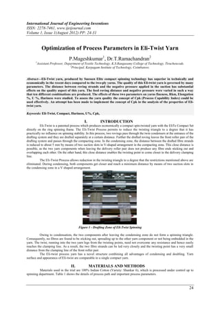
  • 1. International Journal of Engineering Inventions ISSN: 2278-7461, www.ijeijournal.com Volume 1, Issue 1(August 2012) PP: 24-31 Optimization of Process Parameters in Eli-Twist Yarn P.Mageshkumar1, Dr.T.Ramachandran2 1 Assistant Professor, Department of Textile Technology, K.S.Rangasamy College of Technology, Tiruchencode. 2 Principal, Karpagam Institute of Technology, Coimbatore. Abstract––Eli-Twist yarn, produced by Suessen Elite compact spinning technology has superior in technically and economically in the recent days compared to the two-ply yarns. The quality of this Eli-twist yarn is governed by many parameters. The distance between roving strands and the negative pressure applied in the suction has substantial effects on the quality aspect of this yarn. The feed roving distance and negative pressure were varied in such a way that ten different combinations are produced. The effects of these two parameters on yarns fineness, Rkm, Elongation %, U %, Hariness were studied. To assess the yarn quality the concept of Cpk (Process Capability Index) could be used effectively. An attempt has been made to implement the concept of Cpk in the analysis of the properties of Eli- twist yarn. Keywords: Eli-Twist, Compact, Hariness, U%, Cpk, I. INTRODUCTION Eli-Twist is a patented process which produces economically a compact spin-twisted yarn with the EliTe Compact Set directly on the ring spinning frame. The Eli-Twist Process permits to reduce the twisting triangle to a degree that it has practically no influence on spinning stability. In this process, two rovings pass through the twin condensers at the entrance of the drafting system and they are drafted separately at a certain distance. Further the drafted roving leaves the front roller pair of the drafting system and passes through the compacting zone. In the condensing zone, the distance between the drafted fibre strands is reduced to about 5 mm by means of two suction slots in V-shaped arrangement in the compacting zone. This close distance is possible, as the two yarn components when leaving the delivery roller pair does not produce any fibre ends sticking out and overlapping each other. On the other hand, this close distance enables the twisting point to come closer to the delivery clamping line. The Eli-Twist Process allows reduction in the twisting triangle to a degree that the restrictions mentioned above are eliminated. During condensing, both components get closer and reach a minimum distance by means of two suction slots in the condensing zone in a V shaped arrangement. Figure 1 - Drafting Zone of Eli-Twist Spinning Owing to condensation, the two components after leaving the condensing zone do not form a spinning triangle. Consequently, no fibres are found to be sticking out, spreading up to the other yarn component or not being embedded in the yarn. The twist, running into the two yarn legs from the twisting points, need not overcome any resistance and hence easily reaches the clamping line. As a result, the two fibre strands can be led very closely and the twisting point has a very small distance from the clamping line of the front roller pair. The Eli-twist process yarn has a novel structure combining all advantages of condensing and doubling. Yarn surface and appearance of Eli-twist are comparable to a single compact yarn. II. MATERIALS AND METHODS Materials used in the trial are 100% Indian Cotton (Variety: Shankar 6), which is processed under control up to spinning department. Table 1 shows the details of process path and important process parameters. 24
  • 2. Optimization of process parameters in Eli-Twist yarn Table 1 - Spinning Preparatory process parameters Parameters Details Carding LC 300 A V3 a) Delivery Hank 0.120 b) Delivery Speed in mpm 120 c) Production Rate (Kg/hr) 35.4 Pre Comber Draw Frame LD-2 a) No of Doubling 5 b) Delivery Hank 0.120 c) Delivery Speed in mpm 600 Uni Lap E-5 a) No of Doubling 22 b) Lap Weight 75 Comber E-65 a) Delivery Hank 0.120 b) Comber Speed (npm) 450 Finisher Draw Frame D-40 a) Delivery Hank 0.120 b) No of Doublings 8 c) Delivery Speed in mpm 400 Simplex LFS 1660 V a) Delivery Hank 0.9 b) Spindle Speed (rpm) 980 c) TPI / TM 1.40 / 1.48 Ring spinning LR-6 AX – Elitwist Converted 1660 V a)Yarn Count 40/2 b) Avg. Spindle Speed (rpm) 15500 c) TPI 18.0 The process details and parameters given above are common for all the trial samples, whereas the changes have been made only in the spinning parameters. Levels have been decided for the two factors by considering the raw material, atmospheric conditions, economic viability, work methods & possibility of the mills. Table 2 - Factors & Levels Factors Levels Distance between the 2 roving strands 5 (0mm, 2mm,4mm,6mm,8mm) Negative pressure applied in the suction zone 2 (22mbar & 24mbar) The material from Speed frames have been taken for the trials. All the trials have been run in the identical spindles in the ring frame at a constant speed. The distance between the roving strands is optimized by means of specially designed roving guides and the measurement of the distance was taken by using a normal measuring scale. Fig.1 represents both the normal roving guide and the specially designed roving guide present in the drafting zone. 25
  • 3. Optimization of process parameters in Eli-Twist yarn Table 3 - Design of experiments Trials Distance b/w 2 roving strands Suction pressure applied (mbar) in mm Trial 1 0 22 Trial 2 0 24 Trial 3 2 22 Trial 4 2 24 Trial 5 4 22 Trial 6 4 24 Trial 7 6 22 Trial 8 6 24 Trial 9 8 22 Trial 10 8 24 Figure 2 - Specially designed roving guide Figure 3 - Measurement of Negative Pressure III. TESTING PARAMETERS The trial samples have been tested for their count, variation in count, Lea strength, Single yarn strength, Elongation %, number of imperfections, Hairiness and Classimat faults respectively. All the testing has been done by using the latest testing instruments under the standard atmospheric conditions. Testing procedures have been followed as per the testing instrument recommendations. 26
  • 4. Optimization of process parameters in Eli-Twist yarn Table 4 - Testing Process Parameters Test Type Testing Instruments No of Samples Tested Testing Speed (mpm) Count Cascade 30 / Trial NA Lea Strength Statex 30 / Trial 25 m/min Evenness Uster Tester 5 30 / Trial 800 m/min Tensile Properties Uster Tenso Jet 4 30 / Trial 400 m/min Hairiness Zweigle 30 / Trial 500 m/min Classimat Loepfe Zenit 100% samples 1500 mpm (i.e., winding speed) Test results of the samples, both at ring frame cops stage and the final cone stage were tabulated. Apart from the laboratory test results, the online data on the autoconer breakage, online Classimat and the lab data were also included. Laboratory testing has been conducted in the recently developed Uster testing instruments. All the testing has been conducted at standard atmospheric conditions i.e. at 65% relative humidity with dry temperature of 74°F and wet temperature of 66°F respectively. Test Results have been analysed statistically by means of using the concept of CpK (Process Capability Index). The quality of yarn has been assessed by comparing the test results with the specifications/variations. Each parameter has been given certain amount of weightage and the CpK values have been calculated for each trial. IV. RESULTS & DISCUSSION Table 6 - Test results of trail 1, 2 , 3, 4, 5 Requireme Process Parameters nt Trial 1 Trial 2 Trial 3 Trial 4 Trial 5 Count 40/2 40/2 40/2 40/2 40/2 Set TPI / TM 18.2 / 4.06 18.2 / 4.06 18.2 / 4.06 18.2 / 4.06 18.2 / 4.06 Twist Direction S S S S S Package Tested Cone Cone Cone Cone Cone Distance b/w 2 Roving Strands mm 0 2 4 6 8 Negative Pressure applied in Suction Zone (m bar) 22 22 22 22 22 Mea Mea Me Mea Mea Test Results n Cvb n Cvb an Cvb Mean Cvb n Cvb n Cvb Avg Count 20.0 1.3 20.7 0.5 20.6 0.7 20.5 0.6 20.5 0.8 20.5 0.7 Avg Rkm 20.5 7.5 21.9 6.5 21.0 5.3 21.0 5.5 20.7 5.5 21.2 5.4 Elongation % 5.4 7.5 5.5 6.8 5.4 6.0 5.9 6.0 5.7 7.1 5.7 5.5 U% 6.8 2.5 7.4 3.9 7.0 2 7.0 2.8 6.9 1.2 6.9 2.0 316. 0 4.0 0 0 1 0 0.0 0 0.0 Thin -50% 0 Thick +50% 5 35.0 8 57.0 4 85 5 65.0 3 84.0 2 77.0 Neps +200% 8 35.0 8 44.0 4 96 5 85.0 4 58.0 5 63.0 Total Imp / Km 13 16 8 11 7 7 Thin -30% 71 30.0 49 34 45 38.0 24 22.0 27 33.0 Thick +35% 25 35.0 31 30.0 29 31 25 46.0 18 31.0 20 46.0 Neps +140% 25 35.0 29 22.0 26 34 24 34.0 21 36.0 20 35.0 Total Imp / Km 50 131 104 94 63 67 Hairiness 4.8 4.0 4.7 12.1 4.6 4.7 4.6 5.2 4.7 3.9 4.9 3.9 1457 570. 710. 652. 750 35.0 7.3 14.7 543.0 7.3 7.3 7.3 S3 .0 0 0 0 Total CMT Faults 20.0 1.5 38.0 1.5 13.0 1.5 20.0 1.5 33.0 1.5 33.0 1.5 Over all Cpk 0.813 1.106 1.099 1.345 1.261 27
  • 5. Optimization of process parameters in Eli-Twist yarn Table 7 - Test results of trail 6,7,8,9,10 Process Require Parameters ment Trial 6 Trial 7 Trial 8 Trial 9 Trial 10 Count 40/2 40/2 40/2 40/2 40/2 Set TPI / TM 18.2 / 4.06 18.2 / 4.06 18.2 / 4.06 18.2 / 4.06 18.2 / 4.06 Twist Direction S S S S S Package Tested Cone Cone Cone Cone Cone Distance b/w 2 Roving Strands mm 0 2 4 6 8 Negative Pressure applied in Suction Zone (m bar) 24 24 24 24 24 Mea Cv Mea Cv Mea Me Mea Cv Mea Test Results Cvb Cvb n b n b n an n b n Cvb Avg Count 20.0 1.3 20.7 1.2 20.3 0.5 20.7 1.3 20.7 1.2 20.4 0.5 Avg Rkm 20.5 7.5 20.3 7.1 20.5 7.1 19.7 7.2 21.3 5.3 21.3 5.5 Elongation % 5.4 7.5 6.0 7.7 5.7 7.0 5.6 7.5 5.6 6.4 5.5 6.4 U% 6.8 2.5 7.3 2.3 7.0 2.3 7.1 1.0 6.7 1.3 6.9 1.3 Thin -50% 0 0.0 0 0.0 0 0.0 0 0.0 0 0.0 35. 52. 103. 89. Thick +50% 5 6 7 84.0 5 2 1 0 0 0 0 137.0 35. 80. 52. Neps +200% 8 4 7 59.0 9 71.0 5 2 0 0 0 37.0 Total Imp / Km 13 10 14 14 7 3 23. 27. Thin -30% 67 41 26.0 45 16.0 12 23 0 0 37.0 35. 23. 46. Thick +35% 25 26 22 55.0 29 31.0 9 17 0 0 0 22.0 35. 34. Neps +140% 25 25 27 39.0 28 16.0 17 9.0 20 0 0 23.0 Total Imp / Km 50 118 90 102 38 60 Hairiness 4.8 4.0 4.7 8.9 4.3 4.7 4.5 8.6 4.9 3.9 4.9 5.3 35. 819. 718. 454. 667. 819. S3 750 7.3 7.3 7.3 7.3 0 0 0 0 0 0 7.3 Total CMT Faults 20.0 1.5 26.0 1.5 24.0 1.5 25.0 1.5 38.0 1.5 16.0 1.5 Over all Cpk 0.944 0.930 0.813 1.410 1.620 28
  • 6. Optimization of process parameters in Eli-Twist yarn V. EFFECT ON HAIRINESS Surface Plot of Hairiness vs Negative Pressure, Roving Distance 5.0 4.8 Hariness 4.6 4.4 24 23 0.0 Negative Pressure 2.5 22 5.0 7.5 Roving Distance Figure 4 - Surface plot of distance between two roving strands & Suction Pressure on Uster Hairiness index In both the levels of the suction pressure, the distance between two roving stands of 2 mm and 4 mm give less hairiness whereas too higher and lower distances leads to higher hairiness. From the surface plot figure 4, we can understand that the effect of Roving distance and Negative Pressure on Hariness is very linear. In very low distance, the fibre web cannot spread out evenly during drafting, also in higher distances the protruding end cannot be controlled effectively by the suction pressure. This may be the main reason for higher hairiness in both extremes. VI. EFFECT ON RKM Surface Plot of Rkm vs Negative Pressure, Roving Distance 22 21 Rkm 20 24 23 0.0 Negative Pressure 2.5 22 5.0 7.5 Roving Distance Figure 5 - Surface plot of distance between two roving strands & suction pressure on Rkm (Single yarn strength) Rkm value does not change much for the distance between roving strand and negative pressure applied. But the co- efficient of variation between values are higher for higher negative pressure in all the distance between roving stands and the 8 mm distance, gives comparatively lesser co-efficient of variation in both the negative pressures applied. The surface plot shows that at 8 mm distance and 24 mbar negative pressures, the Rkm values are higher. The low negative pressure (22 mbar) does not change the Rkm values much in all the roving distances. This may be due the low compaction effect by low pressure. VII. EFFECT ON TOTAL IMPERFECTIONS Surface Plot of Total Imperfecti vs Negative Pressur, Roving Distance 15 Total Imperfections 10 5 24 23 0.0 Negative Pressure 2.5 22 5.0 7.5 Roving Distance Figure 6 - Surface plot of distance between two roving strand & suction pressure on Total imperfections 29
  • 7. Optimization of process parameters in Eli-Twist yarn The surface plot clearly indicates that total imperfections get reduced while increasing the suction pressure and distance between the roving strands. The roving distance plays a major role on total imperfections than the suction pressure. The defects like Thin -50%, Thick +50%, Neps +200% increase for higher suction pressure, whereas minor defects like Thin -30%, Thick +35%, Neps +140% reduce for higher negative pressure. The co-efficient of variation increases for higher roving distances. This phenomena obeys the single yarn compact principle, as the roving distance increases the spinning triangle also gets increased, the effective control over the edge fibres by drafting roller gets reduced. The higher negative pressure may not effectively utilise for control over the edge fibres. VIII. EFFECT ON YARN UNEVENNESS Surface Plot of Unevenness vs Negative Pressure, Roving Distance 7.4 7.2 Unevenness 7.0 6.8 24 23 0.0 Negative Pressure 2.5 22 5.0 7.5 Roving Distance Figure 7 - Surface plot of distance between two roving strands & suction pressure on yarn unevenness Yarn Unevenness gets reduced for higher distances between roving and suction pressure. The Unevenness gets reduced upto aroving distance of 6 mm drastically and no further significant reduction is realized after 6 mm. There is no significant effect of negative pressure on the Yarn Unevenness. The surface plot graph shows the linear relationship between yarn unevenness and distance between two roving strands. As the distance between two roving strands increase, the Unevenness gets reduced for upto 6 mm distance and after 8 mm distance the Unevenness gets increased. This may be because higher distance leads to poor control over the individual fibre by drafting roller. Also when distance becomes very close, there is not sufficient space to spread out the fibre web. IX. IMPORTANCE GIVEN TO EACH PARAMETER IN Cpk The table given below shows the weightage of each parameter taken for the calculation of CpK. Apart from the average value variation, each parameter has also been considered for calculating the CpK. Weightage of each parameter will vary according to the end use of the product. Table 5 - Weightage given to each test parameter Avg Count 5.0 Avg Rkm 20.0 Elongation % 15.0 U% 5.0 Thick +50% 5.0 Neps +200% 15.0 Thin -30% 2.5 Thick +35% 10.00 Neps +140% 10.00 Hairiness 5.0 S3 2.5 Total CMT Faults 5.0 A model has been developed for predicting the yarn quality at various distances between the roving strands and the negative pressure applied in the suction zone. With this the yarn quality results can be predicted in future without conducting any trials. This in turn will result in saving a lot of time and money involved in conducting such trials. U% = 7.78 - 0.0593 Dist between roving strands - 0.0210 Suction Pressure Thick +50% = 9.40 - 0.700 Dist between roving strands - 0.100 Suction Pressure Neps +200% = 15.5 - 0.125 Dist between roving strands - 0.400 Suction Pressure Rkm = 27.0 + 0.0275 Dist between roving strands - 0.270 Suction Pressure Elong % = -10.4 - 0.0375 Dist between roving strands + 0.730 Suction Pressure 30
  • 8. Optimization of process parameters in Eli-Twist yarn UTH = 4.99 + 0.0375 Dist between roving strands - 0.0200 Suction Pressure S3 = 1940 - 38.0 Distance between roving strands - 45.5 Suction Pressure CMT = 49.0 + 0.75 Distance between roving strands - 0.80 Suction Pressure X. CONCLUSION As the quality of yarn is predicted by means of various parameters such as Unevenness %, Imperfection level, Single yarn strength, Elongation, Classimat faults, performance of the yarn downstream process etc, CpK is found to be the right tool for identifying the right process in spinning mills by considering all the yarn quality parameters based on its end use. The aforesaid analysis proves that the overall yarn quality is better in 8mm strand spacing with 24-mbar negative pressure. Also the model developed is very useful in future for predicting the yarn quality of Eli-twist yarn. Based on the end user the weightage given to each yarn quality parameter will be fine tuned and as a result, the optimum process parameter can be easily identified. REFERENCES 1. Boyles, Russell (1991), "The Taguchi Capability Index", Journal of Quality Technology (Milwaukee, Wisconsin: American Society for Quality Control) 23 (1): 17 – 26, ISSN 0022-4065, OCLC 1800135. 2. Booker, J. M.; Raines, M.; Swift, K. G. (2001). Designing Capable and Reliable Products. Oxford: Butterworth- Heinemann. ISBN 9780750650762. OCLC 47030836. 3. Montgomery, Douglas (2004). Introduction to Statistical Quality Control. New York, New York: John Wiley & Sons, Inc. p. 776. ISBN 9780471656319. OCLC 56729567. 4. Stritof, A. (2003). Compact Spinning for Improved Quality of Ring-Spun Yarns, FIBRES & TEXTILES in Eastern Europe, 11(4), 30–35. 5. Engineering, T. (2004). A Research on the Compact Spinning for Long Staple Yarns, FIBRES & TEXTILES in Eastern Europe, 12(4), 27–31. 6. Ozdil, N., Ozdogan, E., & Demirel, A. (2005). A Comparative Study of the Characteristics of Compact Yarn- Based Knitted Fabrics, FIBRES & TEXTILES in Eastern Europe, 13(2), 39–43. 7. Cheng, K. P. S., & Yu, C. (2003). A Study of Compact Spun Yarns. Textile Research Journal, 73(4), 345–349. doi:10.1177/004051750307300412 8. Basal, G. (2006). Comparison of Properties and Structures of Compact and Conventional Spun Yarns. Textile Research Journal, 76(7), 567–575. doi:10.1177/0040517506065591 9. Beceren, Y., & Nergis, B. U. (2008). Comparison of the Effects of Cotton Yarns Produced by New, Modified and Conventional Spinning Systems on Yarn and Knitted Fabric Performance. Textile Research Journal, 78(4), 297– 303. doi:10.1177/0040517507084434 10. Goktepe, F. (2006). A Comparison of Compact Yarn Properties Produced on Different Systems. Textile Research Journal, 76(3), 226–234. doi:10.1177/0040517506061241 11. Krifa, M. (2006). Compact Spinning Effect on Cotton Yarn Quality: Interactions with Fiber Characteristics. Textile Research Journal, 76(5), 388–399. doi:10.1177/0040517506062648 12. Yilmaz, D., Goktepe, F., Goktepe, O., & Kremenakova, D. (2007). Packing Density of Compact Yarns. Textile Research Journal, 77(9), 661–667. doi:10.1177/0040517507078796 13. www.isixsigma.com 14. www.suessen.com 31