Interfacing 16x2 LCD Display with 8051 Microcontroller
•Als PPTX, PDF herunterladen•
0 gefällt mir•769 views

Lcd interfacing using 8051 and assembly language programming

Empfohlen
Weitere ähnliche Inhalte
Was ist angesagt?
Was ist angesagt? (20)
Ähnlich wie Interfacing 16x2 LCD Display with 8051 Microcontroller
Ähnlich wie Interfacing 16x2 LCD Display with 8051 Microcontroller (20)
Mehr von Vikas Dongre
Mehr von Vikas Dongre (20)
Kürzlich hochgeladen
Kürzlich hochgeladen (20)
Interfacing 16x2 LCD Display with 8051 Microcontroller
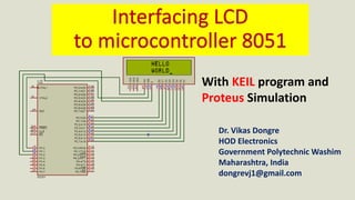
- 1. Dr. Vikas Dongre HOD Electronics Government Polytechnic Washim Maharashtra, India dongrevj1@gmail.com With KEIL program and Proteus Simulation
- 2. LCD is finding widespread use replacing LEDs The declining prices of LCD, descent looking, less power consumption The ability to display numbers, characters, and graphics Incorporation of a refreshing controller into the LCD, thereby relieving the CPU of the task of refreshing the LCD Ease of programming for characters and graphics Seven Segment Display Liquid Crystal Display (LCD) Liquid Crystal Display
- 4. LCD Block DiagramLCD Char 5x7 Matrix 16x2 LCD DISPLAY
- 6. Pin Symbol I/O Description 1 Vss - Ground 2 Vdd - +5V Power Supply 3 Vee - Contrast control power supply 4 RS Register select RS=0 Command register RS=1 Data register 5 R/W I R- Write/ W-Read 6 E I Enable 7-14 DB0-DB7 I/O Data Bus 16x2 LCD Display
- 7. Working of LCD Display controller 1.Command Register: Controls the working of LCD Controller 2.Data Register: Used to store the data to be displayed on LCD 3.Alphanumeric and graphic Character set memory for various languages
- 8. 0 1 2 3 4 5 6 7 8 9 10 11 12 13 14 15 0 80 81 82 83 84 85 86 87 88 89 8A 8B 8C 8D 8E 8F 1 C0 C1 C2 C3 C4 C5 C6 C7 C8 C9 CA CB CC CD CE CF 16x2 LCD DISPLAY ADDRESSES 2 ROWS 16 COLUMNS
- 9. Co de Command to LCD Instruction Register 01 Clear display screen 02 Return home 04 Decrement cursor (shift cursor to left) 06 Increment cursor (shift cursor to right) 05 Shift display right 07 Shift display left 08 Display off, cursor off 0A Display off, cursor on 0C Display on, cursor off Co de Command to LCD Instruction Register 0E Display on, cursor blinking 10 Shift cursor position to left 14 Shift cursor position to right 18 Shift the entire display to the left 1C Shift the entire display to the right 80 Force cursor to beginning to 1st line C0 Force cursor to beginning to 2nd line 38 2 lines and 5x7 matrix
- 10. Algorithm Start Initialize LCD by providing various commands to Control register Send data to be displayed on Data register byte by byte Stop
- 11. COMNWRT: ;send command to LCD MOV P0, A ;copy reg A to port 0 CLR RS ;RS=0 for command Register CLR RW ;R/W=0 for write SETB E ;E=1 for high pulse CLR E ;E=0 for H-to-L pulse ACALL DELAY ;give LCD some time RET Subroutine for Writing in Command Register DATAWRT: ;send command to LCD MOV P0,A ;copy reg A to port 1 SETB RS ;RS=1 for Data Register CLR RW ;R/W=0 for write SETB E ;E=1 for high pulse CLR E ;E=0 for H-to-L pulse ACALL DELAY ;give LCD some time RET Subroutine for Writing in Data Register
- 12. ORG 0000 MOV A,#38H ;INIT. LCD 2 LINES, 5X7 MATRIX ACALL COMNWRT ;call command subroutine MOV A,#0EH ;display on, cursor on ACALL COMNWRT ;call command subroutine MOV A,#01 ;clear LCD ACALL COMNWRT ;call command subroutine MOV A,#06H ;shift cursor right ACALL COMNWRT ;call command subroutine MOV A,#86H ;cursor at line 1, pos. 6 ACALL COMNWRT ;call command subroutine Program to display the word “WORLD” on 16x2 LCD Display Initialize Control register
- 13. MOV A,#“W" ;display letter W ACALL DATAWRT ;call display subroutine MOV A,#“O" ;display letter O ACALL DATAWRT ;call display subroutine MOV A,#“R" ;display letter R ACALL DATAWRT ;call display subroutine MOV A,#“L" ;display L ACALL DATAWRT ;call display subroutine MOV A,#“D" ;display D ACALL DATAWRT ;call display subroutine Send data to be displayed on Data register
- 14. COMNWRT: ;send command to LCD MOV P0,A ;copy reg A to port 1 CLR P1.0 ;RS=0 for command CLR P1.1 ;R/W=0 for write SETB P1.2 ;E=1 for high pulse CLR P1.2 ;E=0 for H-to-L pulse ACALL DELAY ;give LCD some time RET COMMAND WORD SUBROUTINE
- 15. DATAWRT: ;write data to LCD MOV P0,A ;copy reg A to port 1 SETB P1.0 ;RS=1 for DATA CLR P1.1 ;R/W=0 for write SETB P1.2 ;E=1 for high pulse CLR P1.2 ;E=0 for H-to-L pulse ACALL DELAY ;give LCD some time RET DATA WORD SUBROUTINE
- 16. DELAY: MOV R3,#255 ;OUTER COUNT HERE2: MOV R4,#255 ;INNER COUNT HERE: DJNZ R4,HERE ;stay until R4 becomes 0 DJNZ R3,HERE2 RET END DELAY SUBROUTINE
- 17. Output with KEIL program and Proteus Simulation
- 18. Thank you !!! Dr. Vikas Dongre HOD Electronics Government Polytechnic Washim dongrevj1@gmail.com