15 mandibular posteriorcase ll near & angular corrections
•
0 gefällt mir•2,133 views

This document describes the Guide Right system for fabricating and correcting diagnostic and surgical guides. It involves using Invivo5 and Anatomage software to evaluate a case pre-operatively and plan corrections. Guide posts are placed on a cast and bent using a bending tool to achieve linear and angular corrections as determined by the software. A diagnostic guide is fabricated to verify the planned corrections, then a surgical guide is made incorporating the corrections to accurately place implants. The system allows precision placement through in-office fabrication and evaluation of corrections in 1-2 dimensions.

Empfohlen
Empfohlen
Weitere ähnliche Inhalte
Was ist angesagt?
Was ist angesagt? (20)
Ähnlich wie 15 mandibular posteriorcase ll near & angular corrections
Ähnlich wie 15 mandibular posteriorcase ll near & angular corrections (16)
Kürzlich hochgeladen
Kürzlich hochgeladen (20)
15 mandibular posteriorcase ll near & angular corrections
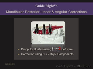
- 1. Guide Right™ Mandibular Posterior Linear & Angular Corrections Invivo5 ■ Preop Evaluation using Anatomage Software ■ Correction using Guide Right Components BLONS 2.2013
- 2. Fabrication of DIAGNOSTIC Guide Straight Guide Posts Cylindrical Guide Sleeves Replacing 28 ▪ 29 ▪ 30
- 3. 3 mm x 8 mm guide posts placed in holes in the cast.
- 4. 3 mm DIAGNOSTIC guide sleeves (1 cleat) placed on 3 mm guide posts Triad® Gel added to form the DIAGNOSTIC guide.
- 5. Invivo5 Anatomage Pre-op Software Evaluation
- 6. # 29 ▪ Initial Alignment ▪ DIAGNOSTIC Guide securely seated in patient for X-ray axial cross sectional Invivo5 Anatomage tangential volumetric
- 7. 1st Angular Correction: # 29 1 st Linear Correction: 0.5LingualOffset to the Lingual ▪ mm 7° Bend to the Lingual tangential cross sectional Invivo5
- 8. # 29 2nd Angular Correction: 2 nd Linear Correction 14º Bend mesial 0.5 mm Offset distal axial cross sectional Invivo5 Anatomage Invivo5 Anatomage tangential volumetric
- 9. # 29 CLOSE UP indication for 14º Angular Correction tangential
- 10. # 30 Initial Alignment ▪ 4.1 X 8 mm virtual implant ▪ Invivo5 Anatomage
- 11. # 30 ▪ Angular Correction: 7° Bend to the Mesial ▪ axial cross sectional Invivo5 Invivo5 Anatomage Anatomage tangential view volumetric
- 12. # 30 CLOSE UP indication for 7° Angular Correction tangential
- 13. # 31 Initial Alignment axial cross sectional Invivo5 Invivo5 Anatomage Anatomage tangential volumetric
- 14. # 31 Angular Correction: 26° Bend to the Lingual axial cross sectional Invivo5 Anatomage tangential volumetric
- 15. # 31 CLOSE UP indication for 26° Lingual Correction cross section
- 16. Review of Pre-op Corrections #29 #30 LINEAR CORRECTIONS ANGULAR CORRECTIONS 1st : 0.5 mm Offset toward the Lingual 7° Bend to the Mesial 2nd : 0.5 mm Offset toward the Distal # 31 ANGULAR CORRECTIONS ANGULAR CORRECTIONS 1st : 14° bend Mesial 26° Bend to the Lingual 2st : 7° bend to the Lingual Cosine is applied to determine correction data. * see Pythagorean Theorem - COSINE CALCULATION slideshow
- 17. # 31 - 26° # 30 - 7° # 29 - 14° 3 mm magnetic guide posts 3 mm X 0.5 mm offset 3 mm magnetic guide posts showing angle corrections
- 18. Fabrication of SURGICAL Guide Magnetic Guide Posts Open Guide Sleeves
- 19. Corrected 3 mm magnetic guide posts in prospective positions
- 20. Initial cast
- 21. 26° 7° 14° Corrected 3 mm guide posts in cast
- 22. Buccal view of SURGICAL guide with 3.3 mm open guide sleeves
- 23. 4.8 mm 4 4.1 mm 4.1 mm Final Implant Placement
- 27. Stage 2
- 29. Guide Right™ Products shown in this case 1 - 3/32” drill 3 - 3 mm Guide Post 3 - 3 mm Guide Sleeve 1 - 3 mm X 0.5 mm Magnetic Offset Guide Post 3 - 3.3 mm Open Guide Sleeve Generation ll ▪ Guide Post Bending Tool Triad® Gel 1.800.314.0065 • www.deplaque.com
- 30. Guide Right™ Generation ll Bending Tool 10° example For more information on use of the bending tool go to www.deplaque.com ▪ Guide Right™ Generation ll Bending Tool
- 31. Guide Right™ GENERATION II ▪ GUIDE POST BENDING TOOL SINGLE BEND review Step 1 Place bending tool plate on a secure flat surface with the degree increments at the top & the stainless steel bar with the v-cut at the bottom. Step 2 Locate 3/32” hole in the center of the v-cut and place the bottom half of the guide post into the hole. Tighten the set screw. Step 3 Locate the hole in the bottom of the stylus that you will use that will fit over the top half of the guide post (3.0 mm, 4.0 mm or 5.0 mm). Step 4 Fit the stylus over the guide post securely with the point directed at zero degrees and the bottom of the stylus in contact with the V block. Step 5 Using the stylus as a lever, bend the guide post to the degree of angle of correction. You may need to ease the point of the stylus beyond the point of the desired degree. Step 6 Loosen screw and remove guide post and the stylus to find the guide post bent to the desired angle.
- 32. Guide Right™ GENERATION II ▪ GUIDE POST BENDING TOOL COMPOUND BEND overview Step 1 Position a straight or offset guide post in the bending plate, tightening the set screw against one of the flat surfaces on the lower half of the guide post. Step 2 The 1st bend can be made to the right or left direction. Step 3 The set screw is loosened and the guide post is rotated 90 ° next flat surface. Step 4 The 2nd bend in the second plane is made after rotating the guide post up away from the surface of the bending plate to register the stylus point back at 0 degrees. Step 5 Slide the stylus support bar down under the stylus until it supports the stylus. Tighten the side screws before making the second bend. Step 6 The second bend can be made in either direction according to the x-ray. Step 7 Remove the stylus and place the guide post back in the cast with the appropriate side indicated by a mark facing the buccal or lingual surface. Be sure the post is in the correct position. If the post needs to be corrected by a linear movement an offset guide post can be used. Off sets available in the 3 mm guide post: 0.5,1,1.5, 2.0 ,or 3.0 mm.
- 33. A System of Components for the fabrication and correction of diagnostic & surgical templates in one or two dimensions In-office or lab fabrication Evaluate with 2D & 3D imaging Allows linear and angular correction Enables precision implant placement Cost effective 1.800.314.0065 • www.deplaque.com
- 34. DéPlaque Guide Right™ Surgical Guide System fabricate ▪ evaluate ▪ correct ▪ verify ▪ place Start With Precision. Place With Confidence.™ 1.800.314.0065 • www.deplaque.com