
Empfohlen
Weitere ähnliche Inhalte
Was ist angesagt?
Was ist angesagt? (20)
Andere mochten auch
Andere mochten auch (20)
Ähnlich wie (19) electronic instruments 1
Ähnlich wie (19) electronic instruments 1 (20)
(19) electronic instruments 1
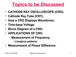
- 1. Topics to be Discussed • CATHODE RAY OSCILLOSCOPE (CRO). (CRO) • Cathode Ray Tube (CRT). • How a CRO Displays Waveforms. • Time-base Voltage. • Block Diagram of a CRO. • APPLICATIONS OF CRO. – Measurement of Frequency. • Lissajous patterns • Measurement of Phase Difference. Difference 17-03-13 12:04 PM Electronic Instruments-1 1
- 2. CATHODE RAY OSCILLOSCOPE (CRO) • The cathode-ray oscilloscope (CRO) is a common laboratory instrument that provides accurate time and amplitude measurements of voltage signals over a wide range of frequencies. • Its reliability, stability, and ease of operation make it suitable as a general purpose laboratory instrument. • The most important and versatile electronic instrument (used in Testing). • It is a very fast x - y plotter and is used to display voltage waveforms. • The ‘stylus’ of this ‘plotter’ is a luminous spot which moves on the screen in response to the input voltages. 17-03-13 12:04 PM Electronic Instruments-1 2
- 3. • An electronics engineer can “see” what is happening in different parts of a circuit. • The heart of the CRO is a cathode-ray tube shown schematically in Fig. 1. • The rest is the electronic circuitry required to operate the CRT. 17-03-13 12:04 PM Electronic Instruments-1 3
- 4. Cathode Ray Tube (CRT) • It consists of : 1. Electron Gun: Produces a sharply focused beam of electrons. 2. Deflection System: Deflects the electron beam, both in horizontal and vertical directions. 3. Fluorescent Screen: Produces a bright spot when the electron beam strikes it. 17-03-13 12:04 PM Electronic Instruments-1 4
- 5. 17-03-13 12:04 PM Electronic Instruments-1 5
- 6. The cathode ray is a beam of electrons which are emitted by the heated cathode (negative electrode) and accelerated toward the fluorescent screen. The assembly of the cathode, intensity grid, focus grid, and accelerating anode (positive electrode) is called an electron gun. Its purpose is to generate the electron beam and control its intensity and focus between the electron gun and the fluorescent screen are two pair of metal plates - one oriented to provide horizontal deflection of the beam and one pair oriented to give vertical deflection to the beam. These plates are thus referred to as the horizontal and vertical deflection plates. The combination of these two deflections allows the beam to reach any portion of the fluorescent screen. Wherever the electron beam hits the screen, the phosphor is excited and light is emitted from that point. This conversion of electron energy into light allows us to write with points or lines of light on an otherwise darkened screen. 17-03-13 12:04 PM Electronic Instruments-1 6
- 7. In the most common use of the oscilloscope the signal to be studied is first amplified and then applied to the vertical (deflection) plates to deflect the beam vertically and at the same time a voltage that increases linearly with time is applied to the horizontal (deflection) plates thus causing the beam to be deflected horizontally at a uniform (constant) rate. The signal applied to the vertical plates is thus displayed on the screen as a function of time. The horizontal axis serves as a uniform time scale. 17-03-13 12:04 PM Electronic Instruments-1 7
- 8. CRO Operation 17-03-13 12:04 PM Electronic Instruments-1 8
- 9. A simplified block diagram of a typical oscilloscope is shown in Fig. 3. In general, the instrument is operated in the following manner. The signal to be displayed is amplified by the vertical amplifier and applied to the vertical deflection plates of the CRT. A portion of the signal in the vertical amplifier is applied to the sweep trigger as a triggering signal. The sweep trigger then generates a pulse coincident with a selected point in the cycle of the triggering signal. This pulse turns on the sweep generator, initiating the sawtooth wave form. The sawtooth wave is amplified by the horizontal amplifier and applied to the horizontal deflection plates. Usually, additional provisions signal are made for applying an external triggering signal or utilizing the 60 Hz line for triggering. Also the sweep generator may be bypassed and an external signal applied directly to the horizontal amplifier. 17-03-13 12:04 PM Electronic Instruments-1 9
- 10. How a CRO Displays Waveforms? The bright spot on the screen moves to the left or to the right when a dc voltage is applied to the horizontal defection plates. 17-03-13 12:04 PM Electronic Instruments-1 10
- 11. A solid line trace is obtained on the screens when we apply ac voltages to the horizontal deflection plates. 17-03-13 12:04 PM Electronic Instruments-1 11
- 12. Display of sine wave on CRO 17-03-13 12:04 PM Electronic Instruments-1 12
- 13. Deflection Sensitivity • It is defined as the vertical deflection of the spot on the screen per unit deflecting voltage applied. • It is designated as S and is measured in m/V. • Deflection factor G, defined as the reciprocal of the deflection sensitivity S. 17-03-13 12:04 PM Electronic Instruments-1 13
- 14. Time-base Voltage Ideal time- Actual time- Distorted base voltage base voltage display 14 17-03-13 12:04 PM Electronic Instruments-1
- 15. Block Diagram of a CRO 1. The CRT, 2. The vertical deflection system, 3. The horizontal defection system, and 4. The high-voltage power supply and the low-voltage power supply. 17-03-13 12:04 PM Electronic Instruments-1 15
- 16. 17-03-13 12:04 PM Electronic Instruments-1 16
- 17. 17-03-13 12:04 PM Electronic Instruments-1 17
- 18. APPLICATIONS OF CRO • (1) Study of Waveforms : – Dual Trace CRO. – Dual Beam CRO. – Storage CRO. • (2) Measurement of Voltages. • (3) Measurement of Current. • (4) Measurement of Frequency. • (5) Measurement of Phase Difference. 17-03-13 12:04 PM Electronic Instruments-1 18
- 19. Measurement of Frequency • Example: A sinusoidal voltage is displayed on a CRO. For obtaining a convenient size of the display as shown in figure, the vertical amplifier/attenuator is set at 2 V/cm, and the time-base control at 0.5 ms/cm. Determine the rms value and the frequency of the sine-wave voltage. 17-03-13 12:04 PM Electronic Instruments-1 19
- 20. 17-03-13 12:04 PM Electronic Instruments-1 20
- 21. Vp = peak value of the display × deflection sensitivity = 3.5 cm × 2 V/cm = 7.0 V 7.0 ∴ rms value = = 4.95 V 2 T = one cycle length on x-axis × time-base setting = 4 cm × 0.5 ms/cm = 2.0 ms 1 1 ∴ f = = = 0.5 kHz T 2 ms 17-03-13 12:04 PM Electronic Instruments-1 21
- 22. Lissajous patterns • A Lissajous pattern is produced on the screen of the CRO when two different sine- wave voltages are simultaneously applied to the two sets of deflection plates. • The type of pattern produced depends on (i) the ratio of the frequencies, and (ii) the relative phase of the two sine-wave voltages. 17-03-13 12:04 PM Electronic Instruments-1 22
- 23. 17-03-13 12:04 PM Electronic Instruments-1 23
- 24. 17-03-13 12:04 PM Electronic Instruments-1 24
- 25. Measurement of Phase Difference http://boson.physics.sc.edu/~hoskins/Demos/CathodeRay.html Y1 sin θ = Y2 17-03-13 12:04 PM Electronic Instruments-1 25