SlideShare a Scribd company logo
1 of 4
Download to read offline
Comparison of EN 12079 & DNV 2.7-1 – selected criteria
Annex A
Materials Materials
Design Design
(6.1) Steel: Shall be impact tested by Charpy impact
(V-notch) method in accordance with EN 10045-1.
Impact test temperature given in Table 1
(3) Steel: Extra high strength steel with specified yield stress
above 500N/mm2 shall not be used.
Steel for primary structure shall be tested by the Charpy
impact (V-notch) method according to EN 10045-1 or DNV’s
“Rules for Classification of ship” Pt.2 Ch.1.
Impact test temperature given in Table 3-1
(5.1.2) Stability against tipping
To prevent container from overturning (tipping) on moving
deck, they shall be designed to withstand tilting of 30
degrees in any direction.
(5.1.6) Design Temperature
TD
shall not be higher than the (statistically) lowest daily
mean temperature for the area where the offshore container
is to operate and in no case shall be higher than -20°C
(5.2.2.1) Lifting loads
shall not exceed σe=0.85C;
For steel: C=Re; where Re is yield stress.
For aluminum:
Base material; C=R0.2
Heat affected zone C=0.7βRm
β=0.8 for ISO AIMg4,5Mn-HAR/AA5083-H32
β=0.7 for all other aluminum alloys
(5.2.2.2) Lifting with lifting set
Design force on primary structure shall be calculated as
2.5Rg,
Pad eyes shall be designed for a total vertical force of 3Rg.
Resultant sling force on each pad eye is calculated as
F=3Rg/(n-1)cosv
With only one pad eye, that pad eye shall be designed for a
total vertical force of 5Rg.
(5.1.1 Part-2) General requirements
In no case shall a sling be rated for an angle of the sling leg
to the vertical in excess of 45 degrees
(5.2.2.3) Lifting with forklift truck
Design force on primary structure shall be calculated as
1.6(R+S)g
(4.1.2) Stability against tipping
To prevent container from overturning (tipping) on moving
deck, they shall be designed to withstand 30 degrees tilting
in any direction without overturning.
(4.1.5) Design Temperature
TD
shall not be taken higher than the (statistically) lowest
daily mean temperature for the area where the offshore
container shall operate and shall not be higher than -20°C
(4.2.1) Allowable Stresses
shall not exceed σe=0.85C;
For steel: C=Re;
For aluminum:
Base material: C=Rp0.2 but not greater than 0.7XRm
Weld and heat affected zone: C=yield strength in the weld
and heat affected zone
	
(4.2.3.1) Lifting with lifting set
The design load on the primary structure shall be taken as:
FL=2.5Rg,
Pad eye shall be designed for a total vertical load of Fp=3Rg
Resulting sling load on each pad eye will be:
RSL=3Rg/(n-1)cosv
Container with one pad eye Fp=5Rg
	
(8.3) Design of lifting sets
In no case shall a sling be designed with an angle of the sling
legs to the vertical larger than 45 degrees
(4.2.3.2) Lifting with forklift truck
Design load on the primary structure shall be taken as:
FF=1.6(R+S)g
EN 12079 (2006) DNV 2.7-1 (2013)
12
Design Design
EN 12079 (2006) DNV 2.7-1 (2013)
(5.2.3.2)	Horizontal Impact
Equivalent shall not exceeds: σe=C
For container post and side rails of the bottom structure 0.25Rg
For other frame members of the side structure, including top rails
0.15Rg
Max calculated deflection for corner post, bottom side rails other
frame members ln/250
(5.2.3.3) Vertical Impact
Vertical point forces 0.25Rg
Calculated deflection shall not exceed ln/250
Equivalent stress shall not exceed σe=C
(5.2.4) Internal forces on container walls
Each wall including the door shall be designed to withstand
an internal force of 0.6xPxg evenly distributed over the whole
surface without suffering any permanent deformation.
(5.2.5) Minimum material thickness
External parts of corner posts and bottom rails
for R≥1000kg, t=6mm;
for R<1000kg, t=4mm
other parts of primary structure t=4mm;
Secondary structure made from metallic materials t=2mm;
For waste skips of monocoque design within an area of up to
100mm from the side edges t=6mm; for remaining parts of the
side structure t=4mm
(5.3) Welding
Essential and non-redundant primary structural members shall be
welded with full penetration welds.
For others primary structure, the use of fillet welds shall
be justified by design appraisal (including calculations and
consideration f failure mode)
Intermittent fillet welding of secondary structure is acceptable;
however care shall be taken to avoid corrosion.
(5.4.1) Floor
Containers liable to fill with water shall have suitable drainage
facility
(5.4.2) Doors and hatches
Shall be designed for same horizontal force as primary structure.
Locking devices shall be secure against opening of the doors
during transport and lifting. Double doors shall have at least one
such locking device on each door, locking directly to the top and
bottom frame.
(4.2.4.1)	Horizontal Impact
The following values shall be used for the static equivalent to an
impact load:
FHI=0.25Rg corner post, side rail of the bottom structure
FHI=0.15Rg for other frame members of the side structure,
including the top rails
Calculated equivalent shall not exceeds: σe=C
Max calculated deflection y=ln/250	
(4.2.4.2) Vertical Impact
Vertical point forces at center span:
FVI=0.25Rg
Calculated deflection shall not exceed
y=ln/250
Equivalent stress shall not exceed σe=C
(4.4.8) Container walls
Each wall including the door shall be designed to withstand an
internal force of Fw=0.6xPxg evenly distributed over the whole
surface without suffering any permanent deformation.
(4.2.5) Minimum material thickness
Corner posts and bottom rails forming outside of the container
t≥6mm;
However, for containers with a max gross mass
R<1000kg the minimum material thickness shall be 4mm,
other parts of primary structure t≥4mm;
Secondary structure made from metallic materials t=2mm;
On waste skips of monocoque design the minimum thickness
within an area of 100mm from the side edges shall be 6mm.
The remaining parts of the side and bottom structure shall be
min. 4mm.
(4.3) Welding
All main welds between pad eyes and the primary structure shall
be full penetration welds.
Essential and non-redundant primary structural members shall be
welded with full penetration welds.
Fork pockets shall be connected to the bottom rails with full
penetration welds but if the fork pockets pass through the
bottom rail, fillet welds may be used.
For others primary structures fillet welds may be permitted after
special agreement with the Society.
Secondary structures may be welded with fillet welds.
Welds between primary and secondary structures are considered
to be welding of secondary structures.
(4.4.5) Floor
Containers liable to fill with water shall have suitable drainage
facility
(4.4.8) Doors and hatches
Shall be designed for same horizontal force as primary structure.
Locking devices shall be secure against opening of the doors
during transport and lifting. Double doors shall have at least
one locking device on each door, locking directly to the top and
bottom frame.
13www.lr.org/offshore-containers
Design Design
EN 12079 (2006) DNV 2.7-1 (2013)
Locking arrangement shall be protected to prevent dislodgement
by impact.
Hinges shall be protected against damage from impact loads.
Doors shall be secured in the open position.
If weathertightness is required, the door shall be equipped with
seals.
(5.4.3) Intermediate cargo decks
When intermediate cargo decks are fitted they shall be designed
to withstand a force of at least 0.5PgΨ uniformly distributed,
Where: Ψ is the dynamic factor=3
(5.4.4) Internal securing points
Containers for general cargo shall have internal securing points.
Each shall be designed to withstand a force of at least 10kN
(5.4.5) Fork lift pockets
Installed in the bottom structure and have a closed top, pass
through the base and be provided with the means to prevent the
container from topping from the forks.
Minimum internal dimensions of forklift pockets shall be 200mm
x 90mm
Forklift pockets shall be located such that the container is stable
during handling and driving with forklift truck.
Pockets shall not be located as far as practicable but need not be
more than 2050mm apart from the center of the pocket to the
center of the pocket.
(5.4.7) Pad eyes
Padeyes shall be aligned with the sling to the center of the lift
with maximum manufacturing tolerance of +/- 2.5.
Any difference in the diagonal measurements between lifting
point centers shall not exceed 0.2% of the length of the
diagonal, or 5mm, whichever is the greater.
Diameter of holes in pad eyes shall match the shackle used,
clearance between shackle pin and pad eye hole shall not exceed
6% of the nominal shackle pin diameter. However, maximum
concentrated stresses at hole edges shall not exceed 2xRe at
design load.
Tolerance between pad eye thickness and inside width of shackle
shall not exceed 25% of the inside width of the shackle
Pad eyes shall be so designed as to permit free movement of the
shackle and sling termination without fouling the pad eye.
Pad eyes shall not protrude outside the boundary of the
containers other than vertical upwards, and shall as far as
possible be designed to avoid damage from the other containers.
Pad eyes shall be welded to the frame with full penetration
welds
(7) Type Testing
Test equipment and calibration
Lifting test: all point lifting and 2-point lifting
Post lifting inspection and examination
Locking arrangement shall be protected to prevent dislodgement
by impact.
Hinges shall be protected against damages from impact loads.
Doors shall be secured in the open position.
If weathertightness is required, the door shall be equipped with
gaskets.
(4.4.2) Intermediate cargo decks
When intermediate cargo decks are fitted, they shall normally be
designed for uniformly distributed load of at least: 0.5PgΨ,
Where load factor: Ψ=3.0
(4.4.10) Internal securing points
Containers for general cargo shall have internal securing points
Each internal lashing point shall be designed for a lashing force
of least 10kN.
(4.4.6) Fork lift pockets
Installed in the bottom structure with closed top,
Minimum opening of the forklift pockets shall be 200mm x
90mm
Forklift pockets shall be located such that the container is stable
during handling and driving with forklift truck.
Pockets shall be located as far as practical. Center distance shall
be at least 900mm apart (where possible) but not more than
2050mm.
Fork pockets shall extend across the full width of the base frame
and shall pass though or be attached to the base. If attached to
the underside of the base rail, detector plate shall be used. Fork
pockets shall have closed tops and sides.
(4.4.1) Pad eyes
Pad eyes shall not protrude outside the boundary of the
container, but may protrude above the top of the container.
Padeyes shall be aligned with the sling to the center of lift with
maximum manufacturing tolerance of +/- 2.5 degrees
Any difference in the diagonal measurements between lifting
point centers shall not exceed 0.2% of the nominal length of the
diagonal, or 5mm, whichever is the greater.
Diameter of holes in pad eyes shall match the shackle used,
clearance between the shackle pin and pad eye hole shall not
exceed 6% of the shackle pin diameter.
Maximum concentrated hot spot stresses at hole edges shall not
exceed 2xRe at design load.
Thickness of the padeye at the hole shall not be less than 75%
of the inside width of the joining shackle.
Pad eyes shall be welded to the frame with full penetration
welds
(4.6) Prototype Testing
Test equipment and calibration
Lifting test: all point lifting and 2-point lifting
14
Design
Fabrication
Design
Fabrication
EN 12079 (2006) DNV 2.7-1 (2013)
Vertical impact test: Drop test and Lowering test
(5.4.10) Coating and corrosion protection
Suitable for offshore environment by means of construction, use
of suitable material and/or corrosion and paint protection
(5.2 Part 2) Dimensions and strength of lifting sets
Annex A and Table 1 shall be used to calculate the minimum
working load limit
Vertical impact test: Drop test and Lowering test
(4.4.13) Coating and corrosion protection
Suitable for offshore environment by means of construction, use
of suitable material and/or corrosion and paint protection
(8.3.1) Dimensions and strength of lifting sets
Table 8.1 and 8.2 shall be used for determination of the
minimum working load limit, WLLmin for lifting sets.
(8.1) Quality Control
The manufacturer shall ensure the quality of procedures and
facilities by implementing a QMS at least in accordance with ISO
9001.
(8.2.2) Approved Welders
Welders shall be approved in accordance with EN 287-1 and EN
ISO 9606-2 as appropriate to the materials being used
(8.2.3) Welding Procedures
Welding procedures shall be in accordance with the relevant
parts of EN ISO 15607, EN ISO 15609-1, EN ISO 15614-1, EN ISO
15614-2 as appropriate.
Impact tests are required as part of the procedure qualification
test. Test temperature and test results shall comply with the
requirements of the standard. Where the test piece thickness
exceeds 12mm four sets of impact tests shall be made (weld
metal, fusion line, HAZ 2mm from fusion line, HAZ 5mm from
fusion line)
(8.2.4) Examination of Welds
Welds shall be subject to visual inspection as specified in Table 7
(requires all welds to be 100% visually inspected).
(8.2.4.2) NDE Methods
Table 8 and Table 9 specify EN reference standards,
(8.2.4.4) NDE Operators
NDE Operators shall be qualified to a minimum of Level 2 of EN
473.
(5.1) Quality Control
The manufacturer shall ensure the quality of procedures and
facilities by implementing a QMS at least in accordance with ISO
9001. An audit of the QMS by the classification society to verify
that they are qualified to manufacture containers according to the
standard. Where the QMS is not fully satisfactory the scope of
inspection by the classification society is adjusted accordingly.
(5.2.1) Approved Welders
Welders shall be approved by the classification society to a
recognised standard, e.g. EN 287-1, EN ISO 9606-1, ISO 9606-2,
ASME IX or ANSI/AWS D1.1
(5.2.2) Welding Procedures
Welding procedures shall be in accordance with the relevant
parts of EN ISO 15607, EN ISO 15609-1, EN ISO 15614-1, EN ISO
15614-2 or other recognised standards (e.g. ANSI/AWS D1.1).
Impact tests are required as part of the procedure qualification
test. Test temperature and test results shall comply with the
requirements of the standard. Where the test piece thickness
exceeds 12mm four sets of impact tests shall be made (weld
metal, fusion line, HAZ 2mm from fusion line, HAZ 5mm from
fusion line)
(5.2.3) Inspection of Welds
Welds shall be subject to visual inspection and NDE. All welds
shall be 100% visually inspected unless otherwise agreed in an
MSA.
(5.2.4) NDE Procedures and NDE Operators
Table 5-2 and Table 5-3 specify EN ISO reference standards, ‘other
recognised standards’ can be used though, and ‘the stipulated
acceptance criteria may in certain cases be modified or made
more severe’ at the discretion of the classification society.
NDE Operators shall be qualified to a minimum of Level 2 of EN
ISO 9712 or an equivalent standard.
15www.lr.org/offshore-containers

More Related Content

What's hot

Tai lieu tinh cau how to-determine-the-crane-capacity-index
Tai lieu tinh cau how to-determine-the-crane-capacity-indexTai lieu tinh cau how to-determine-the-crane-capacity-index
Tai lieu tinh cau how to-determine-the-crane-capacity-index
Phạm Thành
 
Design by Analysis - A general guideline for pressure vessel
Design by Analysis - A general guideline for pressure vesselDesign by Analysis - A general guideline for pressure vessel
Design by Analysis - A general guideline for pressure vessel
AnalyzeForSafety
 
Fabrication of storage buffer vessel
Fabrication of storage buffer vesselFabrication of storage buffer vessel
Fabrication of storage buffer vessel
Nishant Rao Boddeda
 
Crane Safety & Rigging
Crane Safety & RiggingCrane Safety & Rigging
Crane Safety & Rigging
fcarlson
 

What's hot (20)

135613248 lifting-lug
135613248 lifting-lug135613248 lifting-lug
135613248 lifting-lug
 
Crane Rigging Safety by HF & C
Crane Rigging Safety by HF & CCrane Rigging Safety by HF & C
Crane Rigging Safety by HF & C
 
Steam drum lifting
Steam drum liftingSteam drum lifting
Steam drum lifting
 
Lifting Safety
Lifting SafetyLifting Safety
Lifting Safety
 
TANK presentation-2.pptx
TANK presentation-2.pptxTANK presentation-2.pptx
TANK presentation-2.pptx
 
Wall mounted jib crane (h type) report
Wall mounted jib crane (h type) reportWall mounted jib crane (h type) report
Wall mounted jib crane (h type) report
 
Tai lieu tinh cau how to-determine-the-crane-capacity-index
Tai lieu tinh cau how to-determine-the-crane-capacity-indexTai lieu tinh cau how to-determine-the-crane-capacity-index
Tai lieu tinh cau how to-determine-the-crane-capacity-index
 
Storage tank inspection presentation
Storage tank inspection presentationStorage tank inspection presentation
Storage tank inspection presentation
 
Explosives rules 2008
Explosives rules 2008Explosives rules 2008
Explosives rules 2008
 
OFFSHORE PLATFORM_1.ppt (1).pdf
OFFSHORE PLATFORM_1.ppt (1).pdfOFFSHORE PLATFORM_1.ppt (1).pdf
OFFSHORE PLATFORM_1.ppt (1).pdf
 
Wire rope
Wire ropeWire rope
Wire rope
 
Basic riggingworkbook
Basic riggingworkbookBasic riggingworkbook
Basic riggingworkbook
 
Ship Construction (Structure Part)
Ship Construction (Structure Part)Ship Construction (Structure Part)
Ship Construction (Structure Part)
 
Structural analysis of a road bridge using ansys
Structural analysis of a road bridge  using ansysStructural analysis of a road bridge  using ansys
Structural analysis of a road bridge using ansys
 
Design by Analysis - A general guideline for pressure vessel
Design by Analysis - A general guideline for pressure vesselDesign by Analysis - A general guideline for pressure vessel
Design by Analysis - A general guideline for pressure vessel
 
Fabrication of storage buffer vessel
Fabrication of storage buffer vesselFabrication of storage buffer vessel
Fabrication of storage buffer vessel
 
Design and manufacturing of tube bending device
Design and manufacturing of tube bending deviceDesign and manufacturing of tube bending device
Design and manufacturing of tube bending device
 
Rigging and lifting
Rigging and liftingRigging and lifting
Rigging and lifting
 
Crane Safety & Rigging
Crane Safety & RiggingCrane Safety & Rigging
Crane Safety & Rigging
 
Storage Tank.pdf
Storage Tank.pdfStorage Tank.pdf
Storage Tank.pdf
 

Viewers also liked

Installation pdms12.sp6trans
Installation pdms12.sp6transInstallation pdms12.sp6trans
Installation pdms12.sp6trans
Dai Hung
 
Transportation of living quarters behalf of tumbua landana project Angola, We...
Transportation of living quarters behalf of tumbua landana project Angola, We...Transportation of living quarters behalf of tumbua landana project Angola, We...
Transportation of living quarters behalf of tumbua landana project Angola, We...
Dai Hung
 
Copy of set menu 20 & 25 ++ (1)
Copy of set menu 20 & 25 ++ (1)Copy of set menu 20 & 25 ++ (1)
Copy of set menu 20 & 25 ++ (1)
Dai Hung
 
Danh sachthuctapkyi 2012
Danh sachthuctapkyi 2012Danh sachthuctapkyi 2012
Danh sachthuctapkyi 2012
robinking277
 
Construction project management vn
Construction project management vnConstruction project management vn
Construction project management vn
robinking277
 
Baigiang mtb chuong2
Baigiang mtb chuong2Baigiang mtb chuong2
Baigiang mtb chuong2
luuguxd
 
Chuong3 mtb
Chuong3 mtb Chuong3 mtb
Chuong3 mtb
luuguxd
 
10 18-2013 8-33-45 pm
10 18-2013 8-33-45 pm10 18-2013 8-33-45 pm
10 18-2013 8-33-45 pm
robinking277
 
Hướng dẫn sử dụng SACS 5.6
Hướng dẫn sử dụng SACS 5.6Hướng dẫn sử dụng SACS 5.6
Hướng dẫn sử dụng SACS 5.6
luuguxd
 
Bs 2594 1975 welded steel hoztl steek tank_21_dec02
Bs 2594 1975 welded steel hoztl steek tank_21_dec02Bs 2594 1975 welded steel hoztl steek tank_21_dec02
Bs 2594 1975 welded steel hoztl steek tank_21_dec02
robinking277
 
Sacs otc 2012
Sacs otc 2012Sacs otc 2012
Sacs otc 2012
HSD Luu
 
giai phap thi cong neo giu FPSO
giai phap thi cong neo giu FPSOgiai phap thi cong neo giu FPSO
giai phap thi cong neo giu FPSO
trunganh94
 

Viewers also liked (18)

Installation pdms12.sp6trans
Installation pdms12.sp6transInstallation pdms12.sp6trans
Installation pdms12.sp6trans
 
Transportation of living quarters behalf of tumbua landana project Angola, We...
Transportation of living quarters behalf of tumbua landana project Angola, We...Transportation of living quarters behalf of tumbua landana project Angola, We...
Transportation of living quarters behalf of tumbua landana project Angola, We...
 
Copy of set menu 20 & 25 ++ (1)
Copy of set menu 20 & 25 ++ (1)Copy of set menu 20 & 25 ++ (1)
Copy of set menu 20 & 25 ++ (1)
 
Up bài
Up bàiUp bài
Up bài
 
Danh sachthuctapkyi 2012
Danh sachthuctapkyi 2012Danh sachthuctapkyi 2012
Danh sachthuctapkyi 2012
 
Up bài
Up bàiUp bài
Up bài
 
He so nen
He so nenHe so nen
He so nen
 
Construction project management vn
Construction project management vnConstruction project management vn
Construction project management vn
 
Baigiang mtb chuong2
Baigiang mtb chuong2Baigiang mtb chuong2
Baigiang mtb chuong2
 
Chuong3 mtb
Chuong3 mtb Chuong3 mtb
Chuong3 mtb
 
10 18-2013 8-33-45 pm
10 18-2013 8-33-45 pm10 18-2013 8-33-45 pm
10 18-2013 8-33-45 pm
 
Bai giang duong ong
Bai giang duong ongBai giang duong ong
Bai giang duong ong
 
Thi cong 2
Thi cong 2Thi cong 2
Thi cong 2
 
Do an thi cong 2
Do an thi cong 2Do an thi cong 2
Do an thi cong 2
 
Hướng dẫn sử dụng SACS 5.6
Hướng dẫn sử dụng SACS 5.6Hướng dẫn sử dụng SACS 5.6
Hướng dẫn sử dụng SACS 5.6
 
Bs 2594 1975 welded steel hoztl steek tank_21_dec02
Bs 2594 1975 welded steel hoztl steek tank_21_dec02Bs 2594 1975 welded steel hoztl steek tank_21_dec02
Bs 2594 1975 welded steel hoztl steek tank_21_dec02
 
Sacs otc 2012
Sacs otc 2012Sacs otc 2012
Sacs otc 2012
 
giai phap thi cong neo giu FPSO
giai phap thi cong neo giu FPSOgiai phap thi cong neo giu FPSO
giai phap thi cong neo giu FPSO
 

Similar to Comparison of en 12079 &amp; dnv 2.7 1

500630977-CH-1-Pressure-Vessel-Design-1.pdf
500630977-CH-1-Pressure-Vessel-Design-1.pdf500630977-CH-1-Pressure-Vessel-Design-1.pdf
500630977-CH-1-Pressure-Vessel-Design-1.pdf
AnuragKumarSinghSing
 
office final ppt [7760835] final update
office final ppt [7760835] final updateoffice final ppt [7760835] final update
office final ppt [7760835] final update
Aashish Soin
 

Similar to Comparison of en 12079 &amp; dnv 2.7 1 (20)

143137557 storage-tanks
143137557 storage-tanks143137557 storage-tanks
143137557 storage-tanks
 
500630977-CH-1-Pressure-Vessel-Design-1.pdf
500630977-CH-1-Pressure-Vessel-Design-1.pdf500630977-CH-1-Pressure-Vessel-Design-1.pdf
500630977-CH-1-Pressure-Vessel-Design-1.pdf
 
Important Technical Terms in Concrete Design
Important Technical Terms in Concrete DesignImportant Technical Terms in Concrete Design
Important Technical Terms in Concrete Design
 
design prlim.pdf
design prlim.pdfdesign prlim.pdf
design prlim.pdf
 
office final ppt [7760835] final update
office final ppt [7760835] final updateoffice final ppt [7760835] final update
office final ppt [7760835] final update
 
Chemical Equipment Design - Pressure vessel 2.pptx
Chemical Equipment Design - Pressure vessel 2.pptxChemical Equipment Design - Pressure vessel 2.pptx
Chemical Equipment Design - Pressure vessel 2.pptx
 
21 Pump Jack Scaffolding
21 Pump Jack Scaffolding21 Pump Jack Scaffolding
21 Pump Jack Scaffolding
 
Assmann doublewall tank specification
Assmann doublewall tank specificationAssmann doublewall tank specification
Assmann doublewall tank specification
 
Analysis of industrial shed
Analysis of industrial shedAnalysis of industrial shed
Analysis of industrial shed
 
Changes in IS 1893 and IS 13920.pdf
Changes in IS 1893 and IS 13920.pdfChanges in IS 1893 and IS 13920.pdf
Changes in IS 1893 and IS 13920.pdf
 
36405231_seismic_design_steps_153.ppt
36405231_seismic_design_steps_153.ppt36405231_seismic_design_steps_153.ppt
36405231_seismic_design_steps_153.ppt
 
SEISMIC DESIGN STEPS.ppt
SEISMIC DESIGN STEPS.pptSEISMIC DESIGN STEPS.ppt
SEISMIC DESIGN STEPS.ppt
 
Seismic design steps
Seismic design stepsSeismic design steps
Seismic design steps
 
Column math
Column mathColumn math
Column math
 
Casing design
Casing designCasing design
Casing design
 
Shear lug verification example
Shear lug verification exampleShear lug verification example
Shear lug verification example
 
IRJET- Analysis of Steel Silos Subjected to Wind Load with Various Slendernes...
IRJET- Analysis of Steel Silos Subjected to Wind Load with Various Slendernes...IRJET- Analysis of Steel Silos Subjected to Wind Load with Various Slendernes...
IRJET- Analysis of Steel Silos Subjected to Wind Load with Various Slendernes...
 
Horizontal Vessel Loading Calculation
 Horizontal Vessel Loading Calculation Horizontal Vessel Loading Calculation
Horizontal Vessel Loading Calculation
 
Pilework
PileworkPilework
Pilework
 
Qualification under hypothetical accident conditions during transport-R Pal
Qualification under hypothetical accident conditions during transport-R PalQualification under hypothetical accident conditions during transport-R Pal
Qualification under hypothetical accident conditions during transport-R Pal
 

Recently uploaded

Cara Menggugurkan Sperma Yang Masuk Rahim Biyar Tidak Hamil
Cara Menggugurkan Sperma Yang Masuk Rahim Biyar Tidak HamilCara Menggugurkan Sperma Yang Masuk Rahim Biyar Tidak Hamil
Cara Menggugurkan Sperma Yang Masuk Rahim Biyar Tidak Hamil
Cara Menggugurkan Kandungan 087776558899
 
Call Girls in Netaji Nagar, Delhi 💯 Call Us 🔝9953056974 🔝 Escort Service
Call Girls in Netaji Nagar, Delhi 💯 Call Us 🔝9953056974 🔝 Escort ServiceCall Girls in Netaji Nagar, Delhi 💯 Call Us 🔝9953056974 🔝 Escort Service
Call Girls in Netaji Nagar, Delhi 💯 Call Us 🔝9953056974 🔝 Escort Service
9953056974 Low Rate Call Girls In Saket, Delhi NCR
 
Top Rated Call Girls In chittoor 📱 {7001035870} VIP Escorts chittoor
Top Rated Call Girls In chittoor 📱 {7001035870} VIP Escorts chittoorTop Rated Call Girls In chittoor 📱 {7001035870} VIP Escorts chittoor
Top Rated Call Girls In chittoor 📱 {7001035870} VIP Escorts chittoor
dharasingh5698
 

Recently uploaded (20)

Block diagram reduction techniques in control systems.ppt
Block diagram reduction techniques in control systems.pptBlock diagram reduction techniques in control systems.ppt
Block diagram reduction techniques in control systems.ppt
 
Introduction to Serverless with AWS Lambda
Introduction to Serverless with AWS LambdaIntroduction to Serverless with AWS Lambda
Introduction to Serverless with AWS Lambda
 
University management System project report..pdf
University management System project report..pdfUniversity management System project report..pdf
University management System project report..pdf
 
Navigating Complexity: The Role of Trusted Partners and VIAS3D in Dassault Sy...
Navigating Complexity: The Role of Trusted Partners and VIAS3D in Dassault Sy...Navigating Complexity: The Role of Trusted Partners and VIAS3D in Dassault Sy...
Navigating Complexity: The Role of Trusted Partners and VIAS3D in Dassault Sy...
 
Double Revolving field theory-how the rotor develops torque
Double Revolving field theory-how the rotor develops torqueDouble Revolving field theory-how the rotor develops torque
Double Revolving field theory-how the rotor develops torque
 
A Study of Urban Area Plan for Pabna Municipality
A Study of Urban Area Plan for Pabna MunicipalityA Study of Urban Area Plan for Pabna Municipality
A Study of Urban Area Plan for Pabna Municipality
 
Cara Menggugurkan Sperma Yang Masuk Rahim Biyar Tidak Hamil
Cara Menggugurkan Sperma Yang Masuk Rahim Biyar Tidak HamilCara Menggugurkan Sperma Yang Masuk Rahim Biyar Tidak Hamil
Cara Menggugurkan Sperma Yang Masuk Rahim Biyar Tidak Hamil
 
2016EF22_0 solar project report rooftop projects
2016EF22_0 solar project report rooftop projects2016EF22_0 solar project report rooftop projects
2016EF22_0 solar project report rooftop projects
 
Call Girls Pimpri Chinchwad Call Me 7737669865 Budget Friendly No Advance Boo...
Call Girls Pimpri Chinchwad Call Me 7737669865 Budget Friendly No Advance Boo...Call Girls Pimpri Chinchwad Call Me 7737669865 Budget Friendly No Advance Boo...
Call Girls Pimpri Chinchwad Call Me 7737669865 Budget Friendly No Advance Boo...
 
Bhosari ( Call Girls ) Pune 6297143586 Hot Model With Sexy Bhabi Ready For ...
Bhosari ( Call Girls ) Pune  6297143586  Hot Model With Sexy Bhabi Ready For ...Bhosari ( Call Girls ) Pune  6297143586  Hot Model With Sexy Bhabi Ready For ...
Bhosari ( Call Girls ) Pune 6297143586 Hot Model With Sexy Bhabi Ready For ...
 
VIP Model Call Girls Kothrud ( Pune ) Call ON 8005736733 Starting From 5K to ...
VIP Model Call Girls Kothrud ( Pune ) Call ON 8005736733 Starting From 5K to ...VIP Model Call Girls Kothrud ( Pune ) Call ON 8005736733 Starting From 5K to ...
VIP Model Call Girls Kothrud ( Pune ) Call ON 8005736733 Starting From 5K to ...
 
Work-Permit-Receiver-in-Saudi-Aramco.pptx
Work-Permit-Receiver-in-Saudi-Aramco.pptxWork-Permit-Receiver-in-Saudi-Aramco.pptx
Work-Permit-Receiver-in-Saudi-Aramco.pptx
 
Call Girls in Netaji Nagar, Delhi 💯 Call Us 🔝9953056974 🔝 Escort Service
Call Girls in Netaji Nagar, Delhi 💯 Call Us 🔝9953056974 🔝 Escort ServiceCall Girls in Netaji Nagar, Delhi 💯 Call Us 🔝9953056974 🔝 Escort Service
Call Girls in Netaji Nagar, Delhi 💯 Call Us 🔝9953056974 🔝 Escort Service
 
Unleashing the Power of the SORA AI lastest leap
Unleashing the Power of the SORA AI lastest leapUnleashing the Power of the SORA AI lastest leap
Unleashing the Power of the SORA AI lastest leap
 
Hostel management system project report..pdf
Hostel management system project report..pdfHostel management system project report..pdf
Hostel management system project report..pdf
 
Generative AI or GenAI technology based PPT
Generative AI or GenAI technology based PPTGenerative AI or GenAI technology based PPT
Generative AI or GenAI technology based PPT
 
(INDIRA) Call Girl Bhosari Call Now 8617697112 Bhosari Escorts 24x7
(INDIRA) Call Girl Bhosari Call Now 8617697112 Bhosari Escorts 24x7(INDIRA) Call Girl Bhosari Call Now 8617697112 Bhosari Escorts 24x7
(INDIRA) Call Girl Bhosari Call Now 8617697112 Bhosari Escorts 24x7
 
Top Rated Call Girls In chittoor 📱 {7001035870} VIP Escorts chittoor
Top Rated Call Girls In chittoor 📱 {7001035870} VIP Escorts chittoorTop Rated Call Girls In chittoor 📱 {7001035870} VIP Escorts chittoor
Top Rated Call Girls In chittoor 📱 {7001035870} VIP Escorts chittoor
 
data_management_and _data_science_cheat_sheet.pdf
data_management_and _data_science_cheat_sheet.pdfdata_management_and _data_science_cheat_sheet.pdf
data_management_and _data_science_cheat_sheet.pdf
 
Thermal Engineering -unit - III & IV.ppt
Thermal Engineering -unit - III & IV.pptThermal Engineering -unit - III & IV.ppt
Thermal Engineering -unit - III & IV.ppt
 

Comparison of en 12079 &amp; dnv 2.7 1

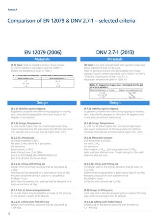
  • 1. Comparison of EN 12079 & DNV 2.7-1 – selected criteria Annex A Materials Materials Design Design (6.1) Steel: Shall be impact tested by Charpy impact (V-notch) method in accordance with EN 10045-1. Impact test temperature given in Table 1 (3) Steel: Extra high strength steel with specified yield stress above 500N/mm2 shall not be used. Steel for primary structure shall be tested by the Charpy impact (V-notch) method according to EN 10045-1 or DNV’s “Rules for Classification of ship” Pt.2 Ch.1. Impact test temperature given in Table 3-1 (5.1.2) Stability against tipping To prevent container from overturning (tipping) on moving deck, they shall be designed to withstand tilting of 30 degrees in any direction. (5.1.6) Design Temperature TD shall not be higher than the (statistically) lowest daily mean temperature for the area where the offshore container is to operate and in no case shall be higher than -20°C (5.2.2.1) Lifting loads shall not exceed σe=0.85C; For steel: C=Re; where Re is yield stress. For aluminum: Base material; C=R0.2 Heat affected zone C=0.7βRm β=0.8 for ISO AIMg4,5Mn-HAR/AA5083-H32 β=0.7 for all other aluminum alloys (5.2.2.2) Lifting with lifting set Design force on primary structure shall be calculated as 2.5Rg, Pad eyes shall be designed for a total vertical force of 3Rg. Resultant sling force on each pad eye is calculated as F=3Rg/(n-1)cosv With only one pad eye, that pad eye shall be designed for a total vertical force of 5Rg. (5.1.1 Part-2) General requirements In no case shall a sling be rated for an angle of the sling leg to the vertical in excess of 45 degrees (5.2.2.3) Lifting with forklift truck Design force on primary structure shall be calculated as 1.6(R+S)g (4.1.2) Stability against tipping To prevent container from overturning (tipping) on moving deck, they shall be designed to withstand 30 degrees tilting in any direction without overturning. (4.1.5) Design Temperature TD shall not be taken higher than the (statistically) lowest daily mean temperature for the area where the offshore container shall operate and shall not be higher than -20°C (4.2.1) Allowable Stresses shall not exceed σe=0.85C; For steel: C=Re; For aluminum: Base material: C=Rp0.2 but not greater than 0.7XRm Weld and heat affected zone: C=yield strength in the weld and heat affected zone (4.2.3.1) Lifting with lifting set The design load on the primary structure shall be taken as: FL=2.5Rg, Pad eye shall be designed for a total vertical load of Fp=3Rg Resulting sling load on each pad eye will be: RSL=3Rg/(n-1)cosv Container with one pad eye Fp=5Rg (8.3) Design of lifting sets In no case shall a sling be designed with an angle of the sling legs to the vertical larger than 45 degrees (4.2.3.2) Lifting with forklift truck Design load on the primary structure shall be taken as: FF=1.6(R+S)g EN 12079 (2006) DNV 2.7-1 (2013) 12
  • 2. Design Design EN 12079 (2006) DNV 2.7-1 (2013) (5.2.3.2) Horizontal Impact Equivalent shall not exceeds: σe=C For container post and side rails of the bottom structure 0.25Rg For other frame members of the side structure, including top rails 0.15Rg Max calculated deflection for corner post, bottom side rails other frame members ln/250 (5.2.3.3) Vertical Impact Vertical point forces 0.25Rg Calculated deflection shall not exceed ln/250 Equivalent stress shall not exceed σe=C (5.2.4) Internal forces on container walls Each wall including the door shall be designed to withstand an internal force of 0.6xPxg evenly distributed over the whole surface without suffering any permanent deformation. (5.2.5) Minimum material thickness External parts of corner posts and bottom rails for R≥1000kg, t=6mm; for R<1000kg, t=4mm other parts of primary structure t=4mm; Secondary structure made from metallic materials t=2mm; For waste skips of monocoque design within an area of up to 100mm from the side edges t=6mm; for remaining parts of the side structure t=4mm (5.3) Welding Essential and non-redundant primary structural members shall be welded with full penetration welds. For others primary structure, the use of fillet welds shall be justified by design appraisal (including calculations and consideration f failure mode) Intermittent fillet welding of secondary structure is acceptable; however care shall be taken to avoid corrosion. (5.4.1) Floor Containers liable to fill with water shall have suitable drainage facility (5.4.2) Doors and hatches Shall be designed for same horizontal force as primary structure. Locking devices shall be secure against opening of the doors during transport and lifting. Double doors shall have at least one such locking device on each door, locking directly to the top and bottom frame. (4.2.4.1) Horizontal Impact The following values shall be used for the static equivalent to an impact load: FHI=0.25Rg corner post, side rail of the bottom structure FHI=0.15Rg for other frame members of the side structure, including the top rails Calculated equivalent shall not exceeds: σe=C Max calculated deflection y=ln/250 (4.2.4.2) Vertical Impact Vertical point forces at center span: FVI=0.25Rg Calculated deflection shall not exceed y=ln/250 Equivalent stress shall not exceed σe=C (4.4.8) Container walls Each wall including the door shall be designed to withstand an internal force of Fw=0.6xPxg evenly distributed over the whole surface without suffering any permanent deformation. (4.2.5) Minimum material thickness Corner posts and bottom rails forming outside of the container t≥6mm; However, for containers with a max gross mass R<1000kg the minimum material thickness shall be 4mm, other parts of primary structure t≥4mm; Secondary structure made from metallic materials t=2mm; On waste skips of monocoque design the minimum thickness within an area of 100mm from the side edges shall be 6mm. The remaining parts of the side and bottom structure shall be min. 4mm. (4.3) Welding All main welds between pad eyes and the primary structure shall be full penetration welds. Essential and non-redundant primary structural members shall be welded with full penetration welds. Fork pockets shall be connected to the bottom rails with full penetration welds but if the fork pockets pass through the bottom rail, fillet welds may be used. For others primary structures fillet welds may be permitted after special agreement with the Society. Secondary structures may be welded with fillet welds. Welds between primary and secondary structures are considered to be welding of secondary structures. (4.4.5) Floor Containers liable to fill with water shall have suitable drainage facility (4.4.8) Doors and hatches Shall be designed for same horizontal force as primary structure. Locking devices shall be secure against opening of the doors during transport and lifting. Double doors shall have at least one locking device on each door, locking directly to the top and bottom frame. 13www.lr.org/offshore-containers
  • 3. Design Design EN 12079 (2006) DNV 2.7-1 (2013) Locking arrangement shall be protected to prevent dislodgement by impact. Hinges shall be protected against damage from impact loads. Doors shall be secured in the open position. If weathertightness is required, the door shall be equipped with seals. (5.4.3) Intermediate cargo decks When intermediate cargo decks are fitted they shall be designed to withstand a force of at least 0.5PgΨ uniformly distributed, Where: Ψ is the dynamic factor=3 (5.4.4) Internal securing points Containers for general cargo shall have internal securing points. Each shall be designed to withstand a force of at least 10kN (5.4.5) Fork lift pockets Installed in the bottom structure and have a closed top, pass through the base and be provided with the means to prevent the container from topping from the forks. Minimum internal dimensions of forklift pockets shall be 200mm x 90mm Forklift pockets shall be located such that the container is stable during handling and driving with forklift truck. Pockets shall not be located as far as practicable but need not be more than 2050mm apart from the center of the pocket to the center of the pocket. (5.4.7) Pad eyes Padeyes shall be aligned with the sling to the center of the lift with maximum manufacturing tolerance of +/- 2.5. Any difference in the diagonal measurements between lifting point centers shall not exceed 0.2% of the length of the diagonal, or 5mm, whichever is the greater. Diameter of holes in pad eyes shall match the shackle used, clearance between shackle pin and pad eye hole shall not exceed 6% of the nominal shackle pin diameter. However, maximum concentrated stresses at hole edges shall not exceed 2xRe at design load. Tolerance between pad eye thickness and inside width of shackle shall not exceed 25% of the inside width of the shackle Pad eyes shall be so designed as to permit free movement of the shackle and sling termination without fouling the pad eye. Pad eyes shall not protrude outside the boundary of the containers other than vertical upwards, and shall as far as possible be designed to avoid damage from the other containers. Pad eyes shall be welded to the frame with full penetration welds (7) Type Testing Test equipment and calibration Lifting test: all point lifting and 2-point lifting Post lifting inspection and examination Locking arrangement shall be protected to prevent dislodgement by impact. Hinges shall be protected against damages from impact loads. Doors shall be secured in the open position. If weathertightness is required, the door shall be equipped with gaskets. (4.4.2) Intermediate cargo decks When intermediate cargo decks are fitted, they shall normally be designed for uniformly distributed load of at least: 0.5PgΨ, Where load factor: Ψ=3.0 (4.4.10) Internal securing points Containers for general cargo shall have internal securing points Each internal lashing point shall be designed for a lashing force of least 10kN. (4.4.6) Fork lift pockets Installed in the bottom structure with closed top, Minimum opening of the forklift pockets shall be 200mm x 90mm Forklift pockets shall be located such that the container is stable during handling and driving with forklift truck. Pockets shall be located as far as practical. Center distance shall be at least 900mm apart (where possible) but not more than 2050mm. Fork pockets shall extend across the full width of the base frame and shall pass though or be attached to the base. If attached to the underside of the base rail, detector plate shall be used. Fork pockets shall have closed tops and sides. (4.4.1) Pad eyes Pad eyes shall not protrude outside the boundary of the container, but may protrude above the top of the container. Padeyes shall be aligned with the sling to the center of lift with maximum manufacturing tolerance of +/- 2.5 degrees Any difference in the diagonal measurements between lifting point centers shall not exceed 0.2% of the nominal length of the diagonal, or 5mm, whichever is the greater. Diameter of holes in pad eyes shall match the shackle used, clearance between the shackle pin and pad eye hole shall not exceed 6% of the shackle pin diameter. Maximum concentrated hot spot stresses at hole edges shall not exceed 2xRe at design load. Thickness of the padeye at the hole shall not be less than 75% of the inside width of the joining shackle. Pad eyes shall be welded to the frame with full penetration welds (4.6) Prototype Testing Test equipment and calibration Lifting test: all point lifting and 2-point lifting 14
  • 4. Design Fabrication Design Fabrication EN 12079 (2006) DNV 2.7-1 (2013) Vertical impact test: Drop test and Lowering test (5.4.10) Coating and corrosion protection Suitable for offshore environment by means of construction, use of suitable material and/or corrosion and paint protection (5.2 Part 2) Dimensions and strength of lifting sets Annex A and Table 1 shall be used to calculate the minimum working load limit Vertical impact test: Drop test and Lowering test (4.4.13) Coating and corrosion protection Suitable for offshore environment by means of construction, use of suitable material and/or corrosion and paint protection (8.3.1) Dimensions and strength of lifting sets Table 8.1 and 8.2 shall be used for determination of the minimum working load limit, WLLmin for lifting sets. (8.1) Quality Control The manufacturer shall ensure the quality of procedures and facilities by implementing a QMS at least in accordance with ISO 9001. (8.2.2) Approved Welders Welders shall be approved in accordance with EN 287-1 and EN ISO 9606-2 as appropriate to the materials being used (8.2.3) Welding Procedures Welding procedures shall be in accordance with the relevant parts of EN ISO 15607, EN ISO 15609-1, EN ISO 15614-1, EN ISO 15614-2 as appropriate. Impact tests are required as part of the procedure qualification test. Test temperature and test results shall comply with the requirements of the standard. Where the test piece thickness exceeds 12mm four sets of impact tests shall be made (weld metal, fusion line, HAZ 2mm from fusion line, HAZ 5mm from fusion line) (8.2.4) Examination of Welds Welds shall be subject to visual inspection as specified in Table 7 (requires all welds to be 100% visually inspected). (8.2.4.2) NDE Methods Table 8 and Table 9 specify EN reference standards, (8.2.4.4) NDE Operators NDE Operators shall be qualified to a minimum of Level 2 of EN 473. (5.1) Quality Control The manufacturer shall ensure the quality of procedures and facilities by implementing a QMS at least in accordance with ISO 9001. An audit of the QMS by the classification society to verify that they are qualified to manufacture containers according to the standard. Where the QMS is not fully satisfactory the scope of inspection by the classification society is adjusted accordingly. (5.2.1) Approved Welders Welders shall be approved by the classification society to a recognised standard, e.g. EN 287-1, EN ISO 9606-1, ISO 9606-2, ASME IX or ANSI/AWS D1.1 (5.2.2) Welding Procedures Welding procedures shall be in accordance with the relevant parts of EN ISO 15607, EN ISO 15609-1, EN ISO 15614-1, EN ISO 15614-2 or other recognised standards (e.g. ANSI/AWS D1.1). Impact tests are required as part of the procedure qualification test. Test temperature and test results shall comply with the requirements of the standard. Where the test piece thickness exceeds 12mm four sets of impact tests shall be made (weld metal, fusion line, HAZ 2mm from fusion line, HAZ 5mm from fusion line) (5.2.3) Inspection of Welds Welds shall be subject to visual inspection and NDE. All welds shall be 100% visually inspected unless otherwise agreed in an MSA. (5.2.4) NDE Procedures and NDE Operators Table 5-2 and Table 5-3 specify EN ISO reference standards, ‘other recognised standards’ can be used though, and ‘the stipulated acceptance criteria may in certain cases be modified or made more severe’ at the discretion of the classification society. NDE Operators shall be qualified to a minimum of Level 2 of EN ISO 9712 or an equivalent standard. 15www.lr.org/offshore-containers