
Recommended
More Related Content
What's hot
What's hot (20)
Similar to Nested state diagrams: advantages of submachines and concurrency
Similar to Nested state diagrams: advantages of submachines and concurrency (20)
Recently uploaded
Recently uploaded (20)
Nested state diagrams: advantages of submachines and concurrency
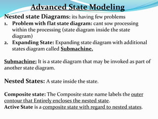
- 1. Nested state Diagrams: its having few problems 1. Problem with flat state diagram: cant sow processing within the processing (state diagram inside the state diagram) 2. Expanding State: Expanding state diagram with additional states diagram called Submachine. Submachine: It is a state diagram that may be invoked as part of another state diagram. Nested States: A state inside the state. Composite state: The Composite state name labels the outer contour that Entirely encloses the nested state. Active State is a composite state with regard to nested states. Advanced State Modeling
- 2. Idle Disconnected TimeOut do/ Sound Beep Dial Tone do/ check con. Dialing Connecting Ringing Connected Warning Do/ Play Msg Recorded Msg do/ play msg Busy Tone do/ selected busy tone ACTIVE Phone Line Repeat Nested States for Phone line
- 3. REVERSENEUTRAL FORWARD Car Transmission Nested States for Phone line SSECONDFIRST THIRD FOURTH reverse Push neutral up up up downdowndown up down Concurrency: Objects are Autonomous entities that can ACT and CHANGE state independent of one another. But sometime Object are also DEPENDANT on another Object causes corresponding state changed. Aggregation Concurrency: also called “and relationship” The Aggregate states: corresponds to the combined states of all the parts. A State diagram for an assembly is a collection of state diagrams.
- 4. REVERSENEUTRAL FORWARD TRANSMISSION Nested States for Phone line SSECONDFIRST THIRD FOURTH reverse Push neutral up up up downdowndown up down CAR BRAKESACCELERATIONTRANSMISSIONIGNITION STARTING IGNITION ONOFF
- 5. Relation of class and State Model: • State model describe the Behavior of the objects of given class • State structure is related to and constrained by class structure. • A object may have different state over time. • A composite state is the aggregation of more than one concurrent sub state. • Three source of concurrency: • First is aggregation of objects • Aggregation within an object • Concurrent behavior of object • State model of a class is inherited by its subclasses • The subclasses inherit both the states of the ancestor and the transitions • The signal hierarchy is independent of the class hierarchy • States are defined by classes and objects • Signals are more fundamental than states and more parallel to classes.
- 6. Interaction Modeling Structural Model : Class and Object diagrams Behavioral Model : State Diagrams Interaction Model : Use Cases/sequence/activity dig. But for Full Behavior : State + Interaction diagrams. Use Cases (Interaction Diagrams): 1. Use cases help to capture the informal requirements. 2. The interaction modeling is the third leg of modeling. 3. Describe how object interact to produce useful result. 4. Interaction can be modeled at different level of abstraction. 5. Use cases explain how system interacts with outside actor
- 7. Sequence Diagram: • It provide more detail and show the message exchanged among a set of objects over time. • Message include both asynchronous signal and procedure calls. • Sequence Diagrams are good for showing the behavior sequence seen by users of a system. Activity Diagram: • It provide further details and show the flow of control among the steps of executions/ Computation. • It show both Data Flow and Control flow. • It Documents the all necessary steps to implements an operation or a business process referenced in a sequence diagrams. Actor: An Actor is a direct external user of a system- an object or set of objects that communicates directly with the system but that is not a part of system.
- 8. Use Cases: • A use cases is a coherent piece of functionality that a system can provide by interacting with actors. • A use cases involves the sequence of message among the system and its actors. • Some use cases have fixed sequence of message. • Error conditions are also part of use cases. • A use cases bring together all the behavior relevant to a slice of system functionality. • Use cases may partition the functionality of the system. Use Cases Diagram: Forms Table Schema
- 9. Guidelines for Use Case Model: 1. First determine the System boundary: identify cases and users 2. Ensure that actors are focused: Actors implement as per their work not by their no. 3. Each Use Case must provide value to users: represent complete functionality, Interaction and Transaction. 4. Relate Use Cases and Actors: Must have at least one Actor in Use Cases and each actor must have to participate in Use Cases. 5. Remember that Use Case are informal: implements user point of view. 6. Use Case can be Structured: smaller fragments using relationship.
- 10. Sequence Model: Scenario: it is a sequence of events that occurs during one particular execution of a system such as for a use cases. Eg. User authentication process Sequence Diagram: shows the • participants in interactions • Sequence of message among them. Sequence Diagram show the interaction of a system with the actors to perform all or part of use case. Each Actor as well as system is represented by a Vertical line called LIFELINE and each Message by Horizontal Arrow from sender to receiver. Guidelines for Sequence Model: 1. Prepare at least one scenario per use case. 2. Abstract the scenario into sequence diagram 3. Divide complex interactions 4. Prepare a sequence diagrams for each error conditions.
- 11. Customer Broker NSE/BSE Log In Secure Communication Display portfolio Enter purchase Data Request Confirmation Confirm Order Place Order Display order no / info Log Out Report Result to Trade Display Goods bought Sequence diagram for share Trading/online stock broker
- 12. Activity Models: shows the • Sequence of steps that makes up a complex process such as algorithms or workflow. • Show steps of computation or processing steps • Shows data flow and control flow. (business flow) An activity diagram is like a traditional flowchart in that it shows the flows of control from steps to steps. 1. Activities: the steps of activity diagrams are Operations/Computations. The purpose of activity diagram is to show the steps within a complex process and sequence constraints among them. 2. Branches: if there is more than one successor to an activity then each arrow may be labeled with a condition in square brackets (called Branches) 3. Initiation and Termination: A solid circle with outgoing arrow shows starting point and Bull Eyes shows end points. 4. Executable activity: transfer of control during execution 5. Concurrent activity: computer separately but deliver at same time
- 13. Verify order Execute order Debit Account Settle Account Close Order Send confirmation Update Portfolio Send failure notice [Success] [Failure] Activity diagram for online trade processing
- 14. Find Seller at Market Price Find buyer at Market price Find buyer at limit price or better Find seller at limit price or better [Market Order] [Buying][Selling] [Selling] [Buying] [Price availability] [Limit order] [Timeout] [Price not available] [order still active]
- 15. Guidelines for Activity Diagram: 1. Don’t misuse activity diagrams: develop use it to study the algorithms and workflow 2. Level diagrams: should shows level of Execution (Preprocessing/processing/Post Processing) 3. Careful about branches and conditions 4. Careful about Concurrent activities 5. Consider executable activity diagrams
- 16. Use cases Relationship: Include Relationship: It incorporate (bind) one use cases within the behavior sequence of another use cases. An include use case is also like SUBROUTINE. Extend Relationship: It adds incremental behavior to use case. Secure Session Edit Password Update Password Trade Stock Intraday Delivery Future/ Option <<include>> <<include>> <<extend>> <<extend>> <<extend>>
- 17. Use cases Relationship: Generalization: It show specific variations on a general use case. It convert analogous to Generalization among classes. Parent use case represents general behavior and child use case extend the parent one. Guidelines for use case relationship: 1. Use case Generalization: 2. Use case Inclusion 3. Use case Extension 4. Include relationship vs. extend Relationship Make Trade Trade Bonds Trade Stocks Commodity
- 18. Make Trade Trade Bonds Trade Stocks Commodity Intraday Delivery Future/ Option <<extend>> <<extend>> <<extend>> Secure Session Edit Password Update Password <<include>> <<include>> Customer NSE/BSE Stock Brokerage System Combination of Use Case Relationship
- 19. Procedural sequence Model: Sequence Diagrams with Passive Objects: • All objects are not active. • Most objects are passive and do not have their own threads of control • A passive objects is not activated until it has been called. • Once execution of an object complete and control returns to the caller then the passive object becomes inactive. Waiter Kitchen Table Bill Table Kitchen Service Food Customer Order Calculate Bill Bill and Payments Slip Food & Bill
- 20. Activation / Focus of Control: The period of time for an object execution as a thin rectangle. This is called the Activation or Focus of Control. Lifeline: The entire period during which the object exist is called Lifeline Sequence Diagrams with Transient Objects: Object A Object B Object C Compute E(c, d) Final Result Result Create C (arg) Operation E(m, n)
- 21. Guidelines for procedural Sequence Models: 1. Active vs Passive Objects 2. Advanced Features Special Constructs for Activity Models: Sending and receiving Signals: Boot Sequence User Login Wait for response Ready Network Request Validation Receive confir.
- 22. Swimlanes: Make sufficient Partition of activities among Organizations. Object Flows: • If there is object flow then there is no meaning to draw control flow. • Objects passes through several states during execution so object flow is essential sometime. • If object have state name then both control flow and propagation of object from state to state is shown by activity diagram. Flight Attendant Ground staff Catering Clean floor Add fuel Load foods CAR Arrive CAR Stop Activity diagram with Object Flow Activity diagram with Swimlanes