SlideShare ist ein Scribd-Unternehmen logo
1 von 20
Downloaden Sie, um offline zu lesen
restart :
with Physics Vectors : Setup mathematicalnotation = true :
FORCE BETWEEN BUS BARS
Camilo Chaves
Electrical Engineer and Physicist
Force between 2 infinite wires (Theory)
dF2
dl2
= i2$dl2 # B1 : Force acting on the wire 2, due to the field B1 generated by the wire1
The field in wire 1 has a simple expression. Hence, the force can be calculated as:
But the wires are infinite and the force everywhere is equal.
So the total Force is: ; note that when the currents has the
same sign, the force is attractive, and when the currents have opposite signs, it repels.
and when the 2 currents are the same, the modulus of the force is:
(1.1)(1.1)
(1.3)(1.3)
(1.4)(1.4)
(1.2)(1.2)
Calculating the Constant Value on the Formula
with ScientificConstants :
m0
= GetValue Constant mu 0 , system = SI $GetUnit Constant mu 0
m0
=
p
2500000
kg m
A2
s2
F =
m0
$ i A 2
2$p $d m
$L m
F =
m0
i2
L
2 p d
A 2
Substituting (1.1) in (1.2)
eval (1.2), (1.1)
F =
i2
L
5000000 d
kg m
A2
s2
A 2
Digits d 3 : sets the maximum number of digits to 3
evalf simplify (1.3)
F =
2.00 10K7
i2
L
d
N
FEA Analysis of the Force between 2 circular wires with the same current
Force Calculation Between 2 wires with 1 Amp current in the same direction (10cm separation)
The forces calculated on the table are from wire 1 and wire 2 , in this order. They are attractive!
In the simulation above, the following parameters were applied:
The current is 1Amp and they are separated by 10cm (0.01m). j0 is the current density.
According to the expression (1.4) we should have:
eval (1.4), i = 1, d = 10$10K2
= F = 2,00 #10 -6
L N
Which differs from the simulated result only because of the size of the mesh chosen!
Force Calculation Between 2 wires with 1 Amp current in the opposite direction (10cm separation)
The forces calculated on the table are from wire 1 and wire 2 , in this order. They are repulsive!
FEA Analysis of the Force between 2 rectangular conductors with the same current
Let's consider a bus bar of 3/8'' in depth and 1'' in width, it has a current capability of 516Amps.
Wid is the width of the Bus
Hei is the Depth of the Bus
J0_Bus is the current density of the Bus produced by a 1Amp current
Dist is the Distance between the geometric center of the Bus
(the rest of the parameters are for the circular wires simulation)
Table of current capacity in Bus Bars
Force Calculation Between 2 Buses with 1 Amp current in the opposite direction
Horizontal Position (10cm separation)
The forces calculated on the table are from Bus 1 and Bus 2 , in this order. They are repulsive!
The result still conform to the equation (1.4), eventhough now the geometry is different.
Force Calculation Between 2 Buses with 1 Amp current in the opposite direction
Vertical Position (10cm separation)
The forces calculated on the table are from Bus 1 and Bus 2 , in this order. They are repulsive!
Force Calculation Between 2 Buses with 1 Amp current in the same direction
Horizontal Position (10cm separation)
The forces calculated on the table are from Bus 1 and Bus 2 , in this order. They are attractive!
Force Calculation Between 2 Buses with 1 Amp current in the same direction
Vertical Position (10cm separation)
The forces calculated on the table are from Bus 1 and Bus 2 , in this order. They are attractive!
(1.3.1)(1.3.1)
FEA Analysis of the Force between 3 Bus Bars in a 50KA Short-Current
J0 d 2.9227$108
:
During a 3 Phase short-current , JA = J0$cos 2$p$60$t , JB = J0$cos 2$p$60$tC
2$p
3
, JC = J0$cos 2$p$60$tK
2$p
3
JA = 2.922700000 108
cos 120 p t , JB = K2.922700000 108
sin 120 p tC
1
6
p , JC = K2.922700000 108
cos 120 p tC
1
3
p
assign (1.3.1)
plot JA, JB, JC , t = 0 ..
1
60
, color = red, blue, green , gridlines = true, title = "Current density of the Bus-Bars in a Short-Circuit"
t
0.002 0.004 0.006 0.008 0.010 0.012 0.014 0.016
K2. #108
K1. #108
0
1. #108
2. #108
Current density of the Bus-Bars in a Short-Circuit
FEA Results in comparison with theoretical values
Force Calculation Between 3 Buses with 50KAmp current
Horizontal Position (10cm separation)
The forces calculated on the table are from Bus 1, Bus 2 and Bus 3 , in this order
(1.3.1.4)(1.3.1.4)
(1.3.1.5)(1.3.1.5)
(1.3.1.2)(1.3.1.2)
(1.3.1.1.3)(1.3.1.1.3)
(1.3.1.1)(1.3.1.1)
(1.3.1.1.2)(1.3.1.1.2)
(1.3.1.1.4)(1.3.1.1.4)
(1.3.1.3)(1.3.1.3)
(1.3.1.1.1)(1.3.1.1.1)
I1 = 2 $50000$cos 2$p$60$t , I2 = 2 $50000$cos 2$p$60$tC
2$p
3
, I3 = 2 $50000$cos 2$p$60$tK
2$p
3
;
I1 = 50000 2 cos 120 p t , I2 = K50000 2 sin 120 p tC
1
6
p , I3 = K50000 2 cos 120 p tC
1
3
p
evalf subs t = 0, (1.3.1.1)
I1 = 70710.67810, I2 = K35355.33906, I3 = K35355.33906
assign (1.3.1.2)
Theoretical Formulas:
F12 =
2$10K7
$ I1$I2
0.1
, F13 =
2$10K7
$ I1$I3
0.2
, F23 =
2$10K7
$ I2$I3
0.1
F12 = K4999.999998, F13 = K2499.999999, F23 = 2500.000000
F11 = F12 CF13, F22 =KF12 CF23, F33 =KF13KF23
F11 = F12 CF13, F22 = KF12 CF23, F33 = KF13 KF23
eval (1.3.1.4), (1.3.1.3)
F11 = K7499.999997, F22 = 7499.999998, F33 = K0.000001
What is the maximum value of the force over time?
(1.3.1.1)
I1 = 50000 2 cos 120 p t , I2 = K50000 2 sin 120 p tC
1
6
p , I3 = K50000 2 cos 120 p tC
1
3
p
F12 =
2$10K7
$ I1$I2
0.1
, F13 =
2$10K7
$ I1$I3
0.2
F12 = 0.000002000000000 I1 I2, F13 = 0.000001000000000 I1 I3
eval %, (1.3.1.1.1)
F12 = K10000.00000 cos 120 p t sin 120 p tC
1
6
p , F13 = K5000.000000 cos 120 p t cos 120 p tC
1
3
p
eval F11 = F12 CF13, (1.3.1.1.3)
F11 = K10000.00000 cos 120 p t sin 120 p tC
1
6
p K5000.000000 cos 120 p t cos 120 p tC
1
3
p
(1.3.1.1.8)(1.3.1.1.8)
(1.3.1.1.5)(1.3.1.1.5)
(1.3.1.1.6)(1.3.1.1.6)
(1.3.1.1.9)(1.3.1.1.9)
(1.3.1.1.7)(1.3.1.1.7)
Diff F11, t = diff rhs (1.3.1.1.4) , t
v
vt
F11 = 1.200000000 10
6
p sin 120 p t sin 120 p tC
1
6
p K1.200000000 10
6
cos 120 p t p cos 120 p tC
1
6
p
C6.000000000 105
p sin 120 p t cos 120 p tC
1
3
p C6.000000000 105
cos 120 p t p sin 120 p tC
1
3
p
t = solve rhs (1.3.1.1.5) = 0, t, allsolutions
t = 0.008333333333 _Z5~C0.0006944444446, 0.008333333333 _Z5~ K0.003472222222
t1 = eval rhs (1.3.1.1.6) , _Z5 = 0 1
t1 = 0.0006944444446
t2 = eval rhs (1.3.1.1.6) , _Z5 = 1 1
t2 = 0.009027777778
First Minimum value: eval (1.3.1.1.4), t = rhs (1.3.1.1.7) = F11 = K8080.127020
Second Minimum value: eval (1.3.1.1.4), t = rhs (1.3.1.1.8) = F11 = K8080.127022
t3 = eval rhs (1.3.1.1.6) , _Z5 = 1 2
t3 = 0.004861111111
First Maximum value: eval (1.3.1.1.4), t = rhs (1.3.1.1.9) = F11 = 580.127018
plot rhs (1.3.1.1.4) , t = 0 ..
1
60
, gridlines = true, title = "Force on Bus 1 over time"
t
0.002 0.006 0.010 0.016
K8000
K7000
K6000
K5000
K4000
K3000
K2000
K1000
0
Force on Bus 1 over time
Checking Calculated results on the FEA solver:
Parameter time was adjusted to give maximum value on BUS BAR 1
Maximum Force Calculation in Bus Bar 1 with 50KAmp current
Horizontal Position (10cm separation) - time = 0.6uS after short circuit
The forces calculated on the table are from Bus 1, Bus 2 and Bus 3 , in this order
evalf convert K8084 N , units, kgf = K824.3385866 kgf
practically this is the equivalt of a mass of 824Kg/m in the Bus Bar.
Conclusion
Forces on Bus Bars can be calculated using F12 =
2$10K7
$ i1$i2
d
and F13 =
2$10K7
$ i1$i2
d
Take the distance d from the geometric center of the bus bar (not on the sides of the bus bar!).
The unit d has to be in meters.
With 3 buses the force between Bus 1 and 3 should also be computed.
Calculate the total force on bus 1: F11 = F12 CF13
For Bus 2 , F22 = F21 CF23 ; F21 =KF12 according to Newtows reaction law.
Compute the currents properly, that means, take the phasors in consideration.
In short-circuits the peak transient current is 2 x Irms
The results confirm that the Panel Builders must take seriously the forces involved during a short-circuit.
Next simulation will determine the distances of the isolators , so that the Copper Bus Bars do not bend!

Weitere ähnliche Inhalte

Was ist angesagt?

TOWNSEND'S CRITERION & LIMITATIONS|BREAKDOWN IN GAS|HIGH VOLTAGE ENGINEERING
TOWNSEND'S CRITERION & LIMITATIONS|BREAKDOWN IN GAS|HIGH VOLTAGE ENGINEERINGTOWNSEND'S CRITERION & LIMITATIONS|BREAKDOWN IN GAS|HIGH VOLTAGE ENGINEERING
TOWNSEND'S CRITERION & LIMITATIONS|BREAKDOWN IN GAS|HIGH VOLTAGE ENGINEERINGPrasant Kumar
 
Power system-protection-presentation-dated-03-10-2013-integrated-protection-c...
Power system-protection-presentation-dated-03-10-2013-integrated-protection-c...Power system-protection-presentation-dated-03-10-2013-integrated-protection-c...
Power system-protection-presentation-dated-03-10-2013-integrated-protection-c...jbpatel7290
 
Gas insulated substation
Gas insulated substationGas insulated substation
Gas insulated substationhimanshu kumar
 
Capacitive voltage transformer (1)
Capacitive voltage transformer (1)Capacitive voltage transformer (1)
Capacitive voltage transformer (1)kaushal boghani
 
Transformers protection, an introduction
Transformers protection, an introductionTransformers protection, an introduction
Transformers protection, an introductionH. Kheir
 
Over current Relays
Over current RelaysOver current Relays
Over current RelaysASWANTH6270
 
Distribution System Voltage Drop and Power Loss Calculation
Distribution System Voltage Drop and Power Loss CalculationDistribution System Voltage Drop and Power Loss Calculation
Distribution System Voltage Drop and Power Loss CalculationAmeen San
 
Chapter 3 Generation of high voltages and current
Chapter 3 Generation of high voltages and currentChapter 3 Generation of high voltages and current
Chapter 3 Generation of high voltages and currentmukund mukund.m
 
Tripping and control of impulse generators
Tripping and control of impulse generatorsTripping and control of impulse generators
Tripping and control of impulse generatorsFariza Zahari
 
Lightning Arrester Working Principle & Types
Lightning Arrester Working Principle & TypesLightning Arrester Working Principle & Types
Lightning Arrester Working Principle & TypesPower System Operation
 
Presentation on 132/33 KVSubstation Training
Presentation on 132/33 KVSubstation Training Presentation on 132/33 KVSubstation Training
Presentation on 132/33 KVSubstation Training Sakshi Rastogi
 
Voltage sag and it’s mitigation
Voltage sag and it’s mitigationVoltage sag and it’s mitigation
Voltage sag and it’s mitigationMayur Dhande
 
A Training Report Of Saltlake 132/33kv Substation
A Training Report Of Saltlake 132/33kv SubstationA Training Report Of Saltlake 132/33kv Substation
A Training Report Of Saltlake 132/33kv SubstationSubhrajit Ghosh
 
Streamer theory of breakdown
Streamer theory of breakdownStreamer theory of breakdown
Streamer theory of breakdownvishalgohel12195
 
SEMINAR Report Of SolarPowerController
SEMINAR Report Of SolarPowerControllerSEMINAR Report Of SolarPowerController
SEMINAR Report Of SolarPowerControllerVaisakh Shanmughan
 

Was ist angesagt? (20)

TOWNSEND'S CRITERION & LIMITATIONS|BREAKDOWN IN GAS|HIGH VOLTAGE ENGINEERING
TOWNSEND'S CRITERION & LIMITATIONS|BREAKDOWN IN GAS|HIGH VOLTAGE ENGINEERINGTOWNSEND'S CRITERION & LIMITATIONS|BREAKDOWN IN GAS|HIGH VOLTAGE ENGINEERING
TOWNSEND'S CRITERION & LIMITATIONS|BREAKDOWN IN GAS|HIGH VOLTAGE ENGINEERING
 
IEEE substation design
IEEE substation designIEEE substation design
IEEE substation design
 
Power system-protection-presentation-dated-03-10-2013-integrated-protection-c...
Power system-protection-presentation-dated-03-10-2013-integrated-protection-c...Power system-protection-presentation-dated-03-10-2013-integrated-protection-c...
Power system-protection-presentation-dated-03-10-2013-integrated-protection-c...
 
Gas insulated substation
Gas insulated substationGas insulated substation
Gas insulated substation
 
Substation
Substation Substation
Substation
 
Capacitive voltage transformer (1)
Capacitive voltage transformer (1)Capacitive voltage transformer (1)
Capacitive voltage transformer (1)
 
Transformers protection, an introduction
Transformers protection, an introductionTransformers protection, an introduction
Transformers protection, an introduction
 
Over current Relays
Over current RelaysOver current Relays
Over current Relays
 
Distribution System Voltage Drop and Power Loss Calculation
Distribution System Voltage Drop and Power Loss CalculationDistribution System Voltage Drop and Power Loss Calculation
Distribution System Voltage Drop and Power Loss Calculation
 
Chapter 3 Generation of high voltages and current
Chapter 3 Generation of high voltages and currentChapter 3 Generation of high voltages and current
Chapter 3 Generation of high voltages and current
 
Tripping and control of impulse generators
Tripping and control of impulse generatorsTripping and control of impulse generators
Tripping and control of impulse generators
 
Lightning Arrester Working Principle & Types
Lightning Arrester Working Principle & TypesLightning Arrester Working Principle & Types
Lightning Arrester Working Principle & Types
 
Presentation on 132/33 KVSubstation Training
Presentation on 132/33 KVSubstation Training Presentation on 132/33 KVSubstation Training
Presentation on 132/33 KVSubstation Training
 
Voltage sag and it’s mitigation
Voltage sag and it’s mitigationVoltage sag and it’s mitigation
Voltage sag and it’s mitigation
 
Get Knowledge About Switchgear
Get Knowledge About SwitchgearGet Knowledge About Switchgear
Get Knowledge About Switchgear
 
BUSBAR PROTECTION
BUSBAR PROTECTIONBUSBAR PROTECTION
BUSBAR PROTECTION
 
A Training Report Of Saltlake 132/33kv Substation
A Training Report Of Saltlake 132/33kv SubstationA Training Report Of Saltlake 132/33kv Substation
A Training Report Of Saltlake 132/33kv Substation
 
Streamer theory of breakdown
Streamer theory of breakdownStreamer theory of breakdown
Streamer theory of breakdown
 
SEMINAR Report Of SolarPowerController
SEMINAR Report Of SolarPowerControllerSEMINAR Report Of SolarPowerController
SEMINAR Report Of SolarPowerController
 
Substation design-guideliness
Substation design-guidelinessSubstation design-guideliness
Substation design-guideliness
 

Andere mochten auch

PLC Control Panel for Tobacco Filling Station
PLC Control Panel for Tobacco Filling StationPLC Control Panel for Tobacco Filling Station
PLC Control Panel for Tobacco Filling StationMuhammad Sarfraz
 
Electrical Control Panels | Variable Frequency Drives | Hazardous Location Pa...
Electrical Control Panels | Variable Frequency Drives | Hazardous Location Pa...Electrical Control Panels | Variable Frequency Drives | Hazardous Location Pa...
Electrical Control Panels | Variable Frequency Drives | Hazardous Location Pa...Jazz Matharu
 
MCC PANEL WIRING, GA and BOM Sample
MCC PANEL WIRING, GA and BOM SampleMCC PANEL WIRING, GA and BOM Sample
MCC PANEL WIRING, GA and BOM SampleShashi Kant
 
Lv switchgear & lv cable sizing
Lv switchgear & lv cable sizingLv switchgear & lv cable sizing
Lv switchgear & lv cable sizingAsif Eqbal
 
Fault Level Calculation
Fault Level CalculationFault Level Calculation
Fault Level CalculationDinesh Sarda
 

Andere mochten auch (8)

2-3
2-32-3
2-3
 
PLC Control Panel for Tobacco Filling Station
PLC Control Panel for Tobacco Filling StationPLC Control Panel for Tobacco Filling Station
PLC Control Panel for Tobacco Filling Station
 
Electrical Control Panels | Variable Frequency Drives | Hazardous Location Pa...
Electrical Control Panels | Variable Frequency Drives | Hazardous Location Pa...Electrical Control Panels | Variable Frequency Drives | Hazardous Location Pa...
Electrical Control Panels | Variable Frequency Drives | Hazardous Location Pa...
 
MCC PANEL WIRING, GA and BOM Sample
MCC PANEL WIRING, GA and BOM SampleMCC PANEL WIRING, GA and BOM Sample
MCC PANEL WIRING, GA and BOM Sample
 
Lv switchgear & lv cable sizing
Lv switchgear & lv cable sizingLv switchgear & lv cable sizing
Lv switchgear & lv cable sizing
 
Cable sizing part 2
Cable sizing part 2Cable sizing part 2
Cable sizing part 2
 
Panel designing
Panel designingPanel designing
Panel designing
 
Fault Level Calculation
Fault Level CalculationFault Level Calculation
Fault Level Calculation
 

Ähnlich wie Forces Between Bus Bars: FEA Analysis and Theoretical Calculations

Eet3082 binod kumar sahu lecturer_14
Eet3082 binod kumar sahu lecturer_14Eet3082 binod kumar sahu lecturer_14
Eet3082 binod kumar sahu lecturer_14BinodKumarSahu5
 
Eet3082 binod kumar sahu lecturer_14
Eet3082 binod kumar sahu lecturer_14Eet3082 binod kumar sahu lecturer_14
Eet3082 binod kumar sahu lecturer_14BinodKumarSahu5
 
EE6604 unit2
EE6604 unit2EE6604 unit2
EE6604 unit2Sri Kumar
 
JEE Main Mock Test - Physics
JEE Main Mock Test - Physics JEE Main Mock Test - Physics
JEE Main Mock Test - Physics Ednexa
 
Two reaction theory
Two reaction theoryTwo reaction theory
Two reaction theoryd_sar
 
12th physics-solution set 3
12th physics-solution set 312th physics-solution set 3
12th physics-solution set 3vandna123
 
chapter 21Electric charge and electric field.pdf
chapter 21Electric charge and electric field.pdfchapter 21Electric charge and electric field.pdf
chapter 21Electric charge and electric field.pdfssusercceaa8
 
16th July 2015 Road lighting_modified
16th July 2015 Road  lighting_modified16th July 2015 Road  lighting_modified
16th July 2015 Road lighting_modifiedPrateek Singh
 
NEET Previous Year Question Paper 2015- StudMonk
NEET Previous Year Question Paper 2015- StudMonkNEET Previous Year Question Paper 2015- StudMonk
NEET Previous Year Question Paper 2015- StudMonkStudMonkNEET
 
Stability with analysis and psa and load flow.ppt
Stability with analysis and psa and load flow.pptStability with analysis and psa and load flow.ppt
Stability with analysis and psa and load flow.pptZahid Yousaf
 
2014 st josephs geelong physics lecture
2014 st josephs geelong physics lecture2014 st josephs geelong physics lecture
2014 st josephs geelong physics lectureAndrew Smith
 
Electric potential numericals
Electric potential numericalsElectric potential numericals
Electric potential numericalsmanu jamwal
 

Ähnlich wie Forces Between Bus Bars: FEA Analysis and Theoretical Calculations (20)

Eet3082 binod kumar sahu lecturer_14
Eet3082 binod kumar sahu lecturer_14Eet3082 binod kumar sahu lecturer_14
Eet3082 binod kumar sahu lecturer_14
 
Eet3082 binod kumar sahu lecturer_14
Eet3082 binod kumar sahu lecturer_14Eet3082 binod kumar sahu lecturer_14
Eet3082 binod kumar sahu lecturer_14
 
12 transformer
12 transformer12 transformer
12 transformer
 
EE6604 unit2
EE6604 unit2EE6604 unit2
EE6604 unit2
 
JEE Main Mock Test - Physics
JEE Main Mock Test - Physics JEE Main Mock Test - Physics
JEE Main Mock Test - Physics
 
Maxwell Equations (2)
Maxwell Equations (2)Maxwell Equations (2)
Maxwell Equations (2)
 
Two reaction theory
Two reaction theoryTwo reaction theory
Two reaction theory
 
Ch29 ssm
Ch29 ssmCh29 ssm
Ch29 ssm
 
Electric-Flux.pptx
Electric-Flux.pptxElectric-Flux.pptx
Electric-Flux.pptx
 
12th physics-solution set 3
12th physics-solution set 312th physics-solution set 3
12th physics-solution set 3
 
chapter 21Electric charge and electric field.pdf
chapter 21Electric charge and electric field.pdfchapter 21Electric charge and electric field.pdf
chapter 21Electric charge and electric field.pdf
 
16th July 2015 Road lighting_modified
16th July 2015 Road  lighting_modified16th July 2015 Road  lighting_modified
16th July 2015 Road lighting_modified
 
Ch30 ssm
Ch30 ssmCh30 ssm
Ch30 ssm
 
Lecture 12
Lecture 12Lecture 12
Lecture 12
 
NEET Previous Year Question Paper 2015- StudMonk
NEET Previous Year Question Paper 2015- StudMonkNEET Previous Year Question Paper 2015- StudMonk
NEET Previous Year Question Paper 2015- StudMonk
 
Stability with analysis and psa and load flow.ppt
Stability with analysis and psa and load flow.pptStability with analysis and psa and load flow.ppt
Stability with analysis and psa and load flow.ppt
 
2014 st josephs geelong physics lecture
2014 st josephs geelong physics lecture2014 st josephs geelong physics lecture
2014 st josephs geelong physics lecture
 
Emf unit i
Emf unit iEmf unit i
Emf unit i
 
Electric potential numericals
Electric potential numericalsElectric potential numericals
Electric potential numericals
 
IEMCON-2015
IEMCON-2015IEMCON-2015
IEMCON-2015
 

Kürzlich hochgeladen

Earthing details of Electrical Substation
Earthing details of Electrical SubstationEarthing details of Electrical Substation
Earthing details of Electrical Substationstephanwindworld
 
Main Memory Management in Operating System
Main Memory Management in Operating SystemMain Memory Management in Operating System
Main Memory Management in Operating SystemRashmi Bhat
 
System Simulation and Modelling with types and Event Scheduling
System Simulation and Modelling with types and Event SchedulingSystem Simulation and Modelling with types and Event Scheduling
System Simulation and Modelling with types and Event SchedulingBootNeck1
 
Internet of things -Arshdeep Bahga .pptx
Internet of things -Arshdeep Bahga .pptxInternet of things -Arshdeep Bahga .pptx
Internet of things -Arshdeep Bahga .pptxVelmuruganTECE
 
Gurgaon ✡️9711147426✨Call In girls Gurgaon Sector 51 escort service
Gurgaon ✡️9711147426✨Call In girls Gurgaon Sector 51 escort serviceGurgaon ✡️9711147426✨Call In girls Gurgaon Sector 51 escort service
Gurgaon ✡️9711147426✨Call In girls Gurgaon Sector 51 escort servicejennyeacort
 
Instrumentation, measurement and control of bio process parameters ( Temperat...
Instrumentation, measurement and control of bio process parameters ( Temperat...Instrumentation, measurement and control of bio process parameters ( Temperat...
Instrumentation, measurement and control of bio process parameters ( Temperat...121011101441
 
Industrial Safety Unit-IV workplace health and safety.ppt
Industrial Safety Unit-IV workplace health and safety.pptIndustrial Safety Unit-IV workplace health and safety.ppt
Industrial Safety Unit-IV workplace health and safety.pptNarmatha D
 
Software and Systems Engineering Standards: Verification and Validation of Sy...
Software and Systems Engineering Standards: Verification and Validation of Sy...Software and Systems Engineering Standards: Verification and Validation of Sy...
Software and Systems Engineering Standards: Verification and Validation of Sy...VICTOR MAESTRE RAMIREZ
 
An experimental study in using natural admixture as an alternative for chemic...
An experimental study in using natural admixture as an alternative for chemic...An experimental study in using natural admixture as an alternative for chemic...
An experimental study in using natural admixture as an alternative for chemic...Chandu841456
 
Arduino_CSE ece ppt for working and principal of arduino.ppt
Arduino_CSE ece ppt for working and principal of arduino.pptArduino_CSE ece ppt for working and principal of arduino.ppt
Arduino_CSE ece ppt for working and principal of arduino.pptSAURABHKUMAR892774
 
THE SENDAI FRAMEWORK FOR DISASTER RISK REDUCTION
THE SENDAI FRAMEWORK FOR DISASTER RISK REDUCTIONTHE SENDAI FRAMEWORK FOR DISASTER RISK REDUCTION
THE SENDAI FRAMEWORK FOR DISASTER RISK REDUCTIONjhunlian
 
Sachpazis Costas: Geotechnical Engineering: A student's Perspective Introduction
Sachpazis Costas: Geotechnical Engineering: A student's Perspective IntroductionSachpazis Costas: Geotechnical Engineering: A student's Perspective Introduction
Sachpazis Costas: Geotechnical Engineering: A student's Perspective IntroductionDr.Costas Sachpazis
 
Class 1 | NFPA 72 | Overview Fire Alarm System
Class 1 | NFPA 72 | Overview Fire Alarm SystemClass 1 | NFPA 72 | Overview Fire Alarm System
Class 1 | NFPA 72 | Overview Fire Alarm Systemirfanmechengr
 
Steel Structures - Building technology.pptx
Steel Structures - Building technology.pptxSteel Structures - Building technology.pptx
Steel Structures - Building technology.pptxNikhil Raut
 
Risk Assessment For Installation of Drainage Pipes.pdf
Risk Assessment For Installation of Drainage Pipes.pdfRisk Assessment For Installation of Drainage Pipes.pdf
Risk Assessment For Installation of Drainage Pipes.pdfROCENODodongVILLACER
 
Concrete Mix Design - IS 10262-2019 - .pptx
Concrete Mix Design - IS 10262-2019 - .pptxConcrete Mix Design - IS 10262-2019 - .pptx
Concrete Mix Design - IS 10262-2019 - .pptxKartikeyaDwivedi3
 
Unit7-DC_Motors nkkjnsdkfnfcdfknfdgfggfg
Unit7-DC_Motors nkkjnsdkfnfcdfknfdgfggfgUnit7-DC_Motors nkkjnsdkfnfcdfknfdgfggfg
Unit7-DC_Motors nkkjnsdkfnfcdfknfdgfggfgsaravananr517913
 
Vishratwadi & Ghorpadi Bridge Tender documents
Vishratwadi & Ghorpadi Bridge Tender documentsVishratwadi & Ghorpadi Bridge Tender documents
Vishratwadi & Ghorpadi Bridge Tender documentsSachinPawar510423
 

Kürzlich hochgeladen (20)

Earthing details of Electrical Substation
Earthing details of Electrical SubstationEarthing details of Electrical Substation
Earthing details of Electrical Substation
 
Main Memory Management in Operating System
Main Memory Management in Operating SystemMain Memory Management in Operating System
Main Memory Management in Operating System
 
System Simulation and Modelling with types and Event Scheduling
System Simulation and Modelling with types and Event SchedulingSystem Simulation and Modelling with types and Event Scheduling
System Simulation and Modelling with types and Event Scheduling
 
Internet of things -Arshdeep Bahga .pptx
Internet of things -Arshdeep Bahga .pptxInternet of things -Arshdeep Bahga .pptx
Internet of things -Arshdeep Bahga .pptx
 
Gurgaon ✡️9711147426✨Call In girls Gurgaon Sector 51 escort service
Gurgaon ✡️9711147426✨Call In girls Gurgaon Sector 51 escort serviceGurgaon ✡️9711147426✨Call In girls Gurgaon Sector 51 escort service
Gurgaon ✡️9711147426✨Call In girls Gurgaon Sector 51 escort service
 
Instrumentation, measurement and control of bio process parameters ( Temperat...
Instrumentation, measurement and control of bio process parameters ( Temperat...Instrumentation, measurement and control of bio process parameters ( Temperat...
Instrumentation, measurement and control of bio process parameters ( Temperat...
 
Industrial Safety Unit-IV workplace health and safety.ppt
Industrial Safety Unit-IV workplace health and safety.pptIndustrial Safety Unit-IV workplace health and safety.ppt
Industrial Safety Unit-IV workplace health and safety.ppt
 
young call girls in Green Park🔝 9953056974 🔝 escort Service
young call girls in Green Park🔝 9953056974 🔝 escort Serviceyoung call girls in Green Park🔝 9953056974 🔝 escort Service
young call girls in Green Park🔝 9953056974 🔝 escort Service
 
Software and Systems Engineering Standards: Verification and Validation of Sy...
Software and Systems Engineering Standards: Verification and Validation of Sy...Software and Systems Engineering Standards: Verification and Validation of Sy...
Software and Systems Engineering Standards: Verification and Validation of Sy...
 
An experimental study in using natural admixture as an alternative for chemic...
An experimental study in using natural admixture as an alternative for chemic...An experimental study in using natural admixture as an alternative for chemic...
An experimental study in using natural admixture as an alternative for chemic...
 
Arduino_CSE ece ppt for working and principal of arduino.ppt
Arduino_CSE ece ppt for working and principal of arduino.pptArduino_CSE ece ppt for working and principal of arduino.ppt
Arduino_CSE ece ppt for working and principal of arduino.ppt
 
THE SENDAI FRAMEWORK FOR DISASTER RISK REDUCTION
THE SENDAI FRAMEWORK FOR DISASTER RISK REDUCTIONTHE SENDAI FRAMEWORK FOR DISASTER RISK REDUCTION
THE SENDAI FRAMEWORK FOR DISASTER RISK REDUCTION
 
Sachpazis Costas: Geotechnical Engineering: A student's Perspective Introduction
Sachpazis Costas: Geotechnical Engineering: A student's Perspective IntroductionSachpazis Costas: Geotechnical Engineering: A student's Perspective Introduction
Sachpazis Costas: Geotechnical Engineering: A student's Perspective Introduction
 
young call girls in Rajiv Chowk🔝 9953056974 🔝 Delhi escort Service
young call girls in Rajiv Chowk🔝 9953056974 🔝 Delhi escort Serviceyoung call girls in Rajiv Chowk🔝 9953056974 🔝 Delhi escort Service
young call girls in Rajiv Chowk🔝 9953056974 🔝 Delhi escort Service
 
Class 1 | NFPA 72 | Overview Fire Alarm System
Class 1 | NFPA 72 | Overview Fire Alarm SystemClass 1 | NFPA 72 | Overview Fire Alarm System
Class 1 | NFPA 72 | Overview Fire Alarm System
 
Steel Structures - Building technology.pptx
Steel Structures - Building technology.pptxSteel Structures - Building technology.pptx
Steel Structures - Building technology.pptx
 
Risk Assessment For Installation of Drainage Pipes.pdf
Risk Assessment For Installation of Drainage Pipes.pdfRisk Assessment For Installation of Drainage Pipes.pdf
Risk Assessment For Installation of Drainage Pipes.pdf
 
Concrete Mix Design - IS 10262-2019 - .pptx
Concrete Mix Design - IS 10262-2019 - .pptxConcrete Mix Design - IS 10262-2019 - .pptx
Concrete Mix Design - IS 10262-2019 - .pptx
 
Unit7-DC_Motors nkkjnsdkfnfcdfknfdgfggfg
Unit7-DC_Motors nkkjnsdkfnfcdfknfdgfggfgUnit7-DC_Motors nkkjnsdkfnfcdfknfdgfggfg
Unit7-DC_Motors nkkjnsdkfnfcdfknfdgfggfg
 
Vishratwadi & Ghorpadi Bridge Tender documents
Vishratwadi & Ghorpadi Bridge Tender documentsVishratwadi & Ghorpadi Bridge Tender documents
Vishratwadi & Ghorpadi Bridge Tender documents
 

Forces Between Bus Bars: FEA Analysis and Theoretical Calculations

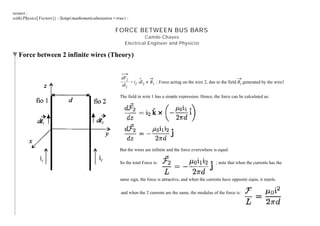
  • 1. restart : with Physics Vectors : Setup mathematicalnotation = true : FORCE BETWEEN BUS BARS Camilo Chaves Electrical Engineer and Physicist Force between 2 infinite wires (Theory) dF2 dl2 = i2$dl2 # B1 : Force acting on the wire 2, due to the field B1 generated by the wire1 The field in wire 1 has a simple expression. Hence, the force can be calculated as: But the wires are infinite and the force everywhere is equal. So the total Force is: ; note that when the currents has the same sign, the force is attractive, and when the currents have opposite signs, it repels. and when the 2 currents are the same, the modulus of the force is:
  • 2. (1.1)(1.1) (1.3)(1.3) (1.4)(1.4) (1.2)(1.2) Calculating the Constant Value on the Formula with ScientificConstants : m0 = GetValue Constant mu 0 , system = SI $GetUnit Constant mu 0 m0 = p 2500000 kg m A2 s2 F = m0 $ i A 2 2$p $d m $L m F = m0 i2 L 2 p d A 2 Substituting (1.1) in (1.2) eval (1.2), (1.1) F = i2 L 5000000 d kg m A2 s2 A 2 Digits d 3 : sets the maximum number of digits to 3 evalf simplify (1.3) F = 2.00 10K7 i2 L d N
  • 3. FEA Analysis of the Force between 2 circular wires with the same current Force Calculation Between 2 wires with 1 Amp current in the same direction (10cm separation) The forces calculated on the table are from wire 1 and wire 2 , in this order. They are attractive!
  • 4. In the simulation above, the following parameters were applied: The current is 1Amp and they are separated by 10cm (0.01m). j0 is the current density. According to the expression (1.4) we should have: eval (1.4), i = 1, d = 10$10K2 = F = 2,00 #10 -6 L N Which differs from the simulated result only because of the size of the mesh chosen!
  • 5. Force Calculation Between 2 wires with 1 Amp current in the opposite direction (10cm separation) The forces calculated on the table are from wire 1 and wire 2 , in this order. They are repulsive!
  • 6. FEA Analysis of the Force between 2 rectangular conductors with the same current Let's consider a bus bar of 3/8'' in depth and 1'' in width, it has a current capability of 516Amps. Wid is the width of the Bus Hei is the Depth of the Bus J0_Bus is the current density of the Bus produced by a 1Amp current Dist is the Distance between the geometric center of the Bus (the rest of the parameters are for the circular wires simulation)
  • 7. Table of current capacity in Bus Bars
  • 8. Force Calculation Between 2 Buses with 1 Amp current in the opposite direction Horizontal Position (10cm separation) The forces calculated on the table are from Bus 1 and Bus 2 , in this order. They are repulsive! The result still conform to the equation (1.4), eventhough now the geometry is different.
  • 9. Force Calculation Between 2 Buses with 1 Amp current in the opposite direction Vertical Position (10cm separation) The forces calculated on the table are from Bus 1 and Bus 2 , in this order. They are repulsive!
  • 10. Force Calculation Between 2 Buses with 1 Amp current in the same direction Horizontal Position (10cm separation) The forces calculated on the table are from Bus 1 and Bus 2 , in this order. They are attractive!
  • 11. Force Calculation Between 2 Buses with 1 Amp current in the same direction Vertical Position (10cm separation) The forces calculated on the table are from Bus 1 and Bus 2 , in this order. They are attractive!
  • 12. (1.3.1)(1.3.1) FEA Analysis of the Force between 3 Bus Bars in a 50KA Short-Current J0 d 2.9227$108 : During a 3 Phase short-current , JA = J0$cos 2$p$60$t , JB = J0$cos 2$p$60$tC 2$p 3 , JC = J0$cos 2$p$60$tK 2$p 3 JA = 2.922700000 108 cos 120 p t , JB = K2.922700000 108 sin 120 p tC 1 6 p , JC = K2.922700000 108 cos 120 p tC 1 3 p assign (1.3.1)
  • 13. plot JA, JB, JC , t = 0 .. 1 60 , color = red, blue, green , gridlines = true, title = "Current density of the Bus-Bars in a Short-Circuit" t 0.002 0.004 0.006 0.008 0.010 0.012 0.014 0.016 K2. #108 K1. #108 0 1. #108 2. #108 Current density of the Bus-Bars in a Short-Circuit
  • 14. FEA Results in comparison with theoretical values Force Calculation Between 3 Buses with 50KAmp current Horizontal Position (10cm separation) The forces calculated on the table are from Bus 1, Bus 2 and Bus 3 , in this order
  • 15. (1.3.1.4)(1.3.1.4) (1.3.1.5)(1.3.1.5) (1.3.1.2)(1.3.1.2) (1.3.1.1.3)(1.3.1.1.3) (1.3.1.1)(1.3.1.1) (1.3.1.1.2)(1.3.1.1.2) (1.3.1.1.4)(1.3.1.1.4) (1.3.1.3)(1.3.1.3) (1.3.1.1.1)(1.3.1.1.1) I1 = 2 $50000$cos 2$p$60$t , I2 = 2 $50000$cos 2$p$60$tC 2$p 3 , I3 = 2 $50000$cos 2$p$60$tK 2$p 3 ; I1 = 50000 2 cos 120 p t , I2 = K50000 2 sin 120 p tC 1 6 p , I3 = K50000 2 cos 120 p tC 1 3 p evalf subs t = 0, (1.3.1.1) I1 = 70710.67810, I2 = K35355.33906, I3 = K35355.33906 assign (1.3.1.2) Theoretical Formulas: F12 = 2$10K7 $ I1$I2 0.1 , F13 = 2$10K7 $ I1$I3 0.2 , F23 = 2$10K7 $ I2$I3 0.1 F12 = K4999.999998, F13 = K2499.999999, F23 = 2500.000000 F11 = F12 CF13, F22 =KF12 CF23, F33 =KF13KF23 F11 = F12 CF13, F22 = KF12 CF23, F33 = KF13 KF23 eval (1.3.1.4), (1.3.1.3) F11 = K7499.999997, F22 = 7499.999998, F33 = K0.000001 What is the maximum value of the force over time? (1.3.1.1) I1 = 50000 2 cos 120 p t , I2 = K50000 2 sin 120 p tC 1 6 p , I3 = K50000 2 cos 120 p tC 1 3 p F12 = 2$10K7 $ I1$I2 0.1 , F13 = 2$10K7 $ I1$I3 0.2 F12 = 0.000002000000000 I1 I2, F13 = 0.000001000000000 I1 I3 eval %, (1.3.1.1.1) F12 = K10000.00000 cos 120 p t sin 120 p tC 1 6 p , F13 = K5000.000000 cos 120 p t cos 120 p tC 1 3 p eval F11 = F12 CF13, (1.3.1.1.3) F11 = K10000.00000 cos 120 p t sin 120 p tC 1 6 p K5000.000000 cos 120 p t cos 120 p tC 1 3 p
  • 16. (1.3.1.1.8)(1.3.1.1.8) (1.3.1.1.5)(1.3.1.1.5) (1.3.1.1.6)(1.3.1.1.6) (1.3.1.1.9)(1.3.1.1.9) (1.3.1.1.7)(1.3.1.1.7) Diff F11, t = diff rhs (1.3.1.1.4) , t v vt F11 = 1.200000000 10 6 p sin 120 p t sin 120 p tC 1 6 p K1.200000000 10 6 cos 120 p t p cos 120 p tC 1 6 p C6.000000000 105 p sin 120 p t cos 120 p tC 1 3 p C6.000000000 105 cos 120 p t p sin 120 p tC 1 3 p t = solve rhs (1.3.1.1.5) = 0, t, allsolutions t = 0.008333333333 _Z5~C0.0006944444446, 0.008333333333 _Z5~ K0.003472222222 t1 = eval rhs (1.3.1.1.6) , _Z5 = 0 1 t1 = 0.0006944444446 t2 = eval rhs (1.3.1.1.6) , _Z5 = 1 1 t2 = 0.009027777778 First Minimum value: eval (1.3.1.1.4), t = rhs (1.3.1.1.7) = F11 = K8080.127020 Second Minimum value: eval (1.3.1.1.4), t = rhs (1.3.1.1.8) = F11 = K8080.127022 t3 = eval rhs (1.3.1.1.6) , _Z5 = 1 2 t3 = 0.004861111111 First Maximum value: eval (1.3.1.1.4), t = rhs (1.3.1.1.9) = F11 = 580.127018
  • 17. plot rhs (1.3.1.1.4) , t = 0 .. 1 60 , gridlines = true, title = "Force on Bus 1 over time" t 0.002 0.006 0.010 0.016 K8000 K7000 K6000 K5000 K4000 K3000 K2000 K1000 0 Force on Bus 1 over time
  • 18. Checking Calculated results on the FEA solver: Parameter time was adjusted to give maximum value on BUS BAR 1
  • 19. Maximum Force Calculation in Bus Bar 1 with 50KAmp current Horizontal Position (10cm separation) - time = 0.6uS after short circuit The forces calculated on the table are from Bus 1, Bus 2 and Bus 3 , in this order evalf convert K8084 N , units, kgf = K824.3385866 kgf practically this is the equivalt of a mass of 824Kg/m in the Bus Bar.
  • 20. Conclusion Forces on Bus Bars can be calculated using F12 = 2$10K7 $ i1$i2 d and F13 = 2$10K7 $ i1$i2 d Take the distance d from the geometric center of the bus bar (not on the sides of the bus bar!). The unit d has to be in meters. With 3 buses the force between Bus 1 and 3 should also be computed. Calculate the total force on bus 1: F11 = F12 CF13 For Bus 2 , F22 = F21 CF23 ; F21 =KF12 according to Newtows reaction law. Compute the currents properly, that means, take the phasors in consideration. In short-circuits the peak transient current is 2 x Irms The results confirm that the Panel Builders must take seriously the forces involved during a short-circuit. Next simulation will determine the distances of the isolators , so that the Copper Bus Bars do not bend!