IIIE SECTION A MANUFACTURING TECHNOLOGY NOTES 9.design for gating and rising
•Download as DOC, PDF•
2 likes•1,185 views

Risers are reservoirs built into casting molds to prevent cavities from shrinkage. They are located at the top of the casting and their volume is 25-55% of the casting. Riser design aims to overcome problems from uneven solidification like voids or stresses. The size and placement of risers depends on factors like the shape and freezing rate of the casting. Gating systems convey liquid material to molds, and their design controls shrinkage, flow speed, turbulence and traps dross. Gates are attached at thick parts to control shrinkage, and multiple gates may be needed for large castings.

Recommended
More Related Content
What's hot
What's hot (20)
Viewers also liked
Similar to IIIE SECTION A MANUFACTURING TECHNOLOGY NOTES 9.design for gating and rising
Similar to IIIE SECTION A MANUFACTURING TECHNOLOGY NOTES 9.design for gating and rising (20)
More from Bhaskar Nagarajan
More from Bhaskar Nagarajan (20)
Recently uploaded
Recently uploaded (20)
IIIE SECTION A MANUFACTURING TECHNOLOGY NOTES 9.design for gating and rising
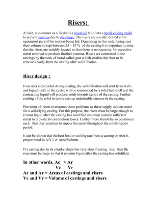
- 1. Risers: A riser, also known as a feeder is a reservoir built into a metal casting mold to prevent cavities due to shrinkage. The risers are usually located at the uppermost part of the section being fed. Depending on the metal being cast their volume is kept between 25 – 55 % of the casting.It is important to note that the risers are suitably located so that there is no necessity for excessive metal removal to produce finished contour. Risers are connected to the castings by the neck of metal called gate which enables the riser to be removed easily from the casting after solidification. Riser design : If no riser is provided during casting, the solidification will start from walls and liquid metal in the centre will be surrounded by a solidified shell and the contracting liquid will produce voids towards centre of the casting. Further cooling of the solid in centre sets up undesirable stresses in the casting. Provision of risers overcomes these problems as these supply molten metal for a solidifying casting. For this purpose, the risers must be large enough to remain liquid after the casting has solidified and must contain sufficient metal to provide for contraction losses. Further these should be so positioned such that they continue to supply the metal throughout the solidification period. It can be shown that the heat loss or cooling rate from a casting or riser is proportional to A/V i. e. Area/Volume. If a casting due to its chunky shape has very slow freezing rate, then the riser must be large so that it remains liquid after the casting has solidified, In other words, Ac > Ar Vc Vr Ac and Ar = Areas of castings and risers Vc and Vr = Volume of castings and risers
- 2. If casting is fast freezing one, then size of the riser need not be large. Minimum size of the riser can be determined by a risering curve which is a hyperbolic relation between the freezing ratio . Ac/Vc = a Ar/Vr + C Vr - b Vc a = Freezing characteristic constant for metal( for steel is 0.1) b = contraction ratio from liquid to solid( for steel 0.3) c = relative freezing rate of riser and casting.It is unity if the same mould material is used for both casting and riser) The proper placement of riser is equally important since it should be able to feed the solidifying casting effectively. If the casting is of cubical or spherical shape, ( i. e chunky shape having low value of Ac/Vc) then a single riser is sufficient to feed casting on solidification. However when value of Ac/Vc high as in case of plate and bar shaped castings more than one riser may be required. If only single riser is used in such cases,then the slushy state just prior to solidification may restricts metal flow from a single riser and may cause centre line shrinkage As a thumb rule it can be said that a single riser is adequate if the if feeding length is less than 4.5 times the thickness of plate for 12-100 mm thick steel plates. In the case of sq bars of size 50 –200 mm, a central riser can be used for distances less than 6 times the sq root of bar size. Longer feeding distances than above are possible by use of chills which will increase the cooling rate and reduce the centre line feeding resistance. In case of alloys having higher centre line feeding resistance than steel, chills have to be used to ensure soundness of those parts of the casting enquiring the greatest strength.
- 3. Gating System and design The gating system serves many purposes, the most important being conveying the liquid material to the mold, but also controlling shrinkage, the speed of the liquid, turbulence, and trapping dross. The gates are usually attached to the thickest part of the casting to assist in controlling shrinkage. In especially large castings multiple gates or runners may be required to introduce metal to more than one point in the mold cavity. The speed of the material is important because if the material is traveling too slowly it can cool before completely filling, leading to misruns and cold shuts. If the material is moving too fast then the liquid material can erode the mold and contaminate the final casting. The shape and length of the gating system can also control how quickly the material cools; short round or square channels minimize heat loss.[8] The gating system may be designed to minimize turbulence, depending on the material being cast. For example, steel, cast iron, and most copper alloys are turbulent insensitive, but aluminium and magnesium alloys are turbulent sensitive. The turbulent insensitive materials usually have a short and open gating system to fill the mold as quickly as possible.
- 4. However, for turbulent sensitive materials short sprues are used to minimize the distance the material must fall when entering the mold. Rectangular pouring cups and tapered sprues are used to prevent the formation of a vortex as the material flows into the mold; these vortices tend to suck gas and oxides into the mold. A large sprue well is used to dissipate the kinetic energy of the liquid material as it falls down the sprue, decreasing turbulence. The choke, which is the smallest cross-sectional area in the gating system used to control flow, can be placed near the sprue well to slow down and smooth out the flow. Note that on some molds the choke is still placed on the gates to make separation of the part easier, but induces extreme turbulence.[9] The gates are usually attached to the bottom of the casting to minimize turbulence and splashing.[8] The gating system may also be designed to trap dross. One method is to take advantage of the fact that some dross has a lower density than the base material so it floats to the top of the gating system. Therefore long flat runners with gates that exit from the bottom of the runners can trap dross in the runners; note that long flat runners will cool the material more rapidly than round or square runners. For materials where the dross is a similar density to the base material, such as aluminium, runner
- 5. extensions and runner wells can be advantageous. These take advantage of the fact that the dross is usually located at the beginning of the pour, therefore the runner is extended past the last gate(s) and the contaminates are contained in the wells. Screens or filters may also be used to trap contaminates.[9] It is important to keep the size of the gating system small, because it all must be cut from the casting and remelted to be reused. The efficiency, or yield, of a casting system can be calculated by dividing the weight of the casting by the weight of the metal poured. Therefore, the higher the number the more efficient the gating system/risers.
- 6. extensions and runner wells can be advantageous. These take advantage of the fact that the dross is usually located at the beginning of the pour, therefore the runner is extended past the last gate(s) and the contaminates are contained in the wells. Screens or filters may also be used to trap contaminates.[9] It is important to keep the size of the gating system small, because it all must be cut from the casting and remelted to be reused. The efficiency, or yield, of a casting system can be calculated by dividing the weight of the casting by the weight of the metal poured. Therefore, the higher the number the more efficient the gating system/risers.