1 2012-production of pea protein concentrates by ultrafltration-influence of hollow-fibre module
•
1 like•285 views

diafiltration for purification of protein isolate

Recommended
More Related Content
What's hot
What's hot (20)
Viewers also liked
Viewers also liked (18)
Similar to 1 2012-production of pea protein concentrates by ultrafltration-influence of hollow-fibre module
Similar to 1 2012-production of pea protein concentrates by ultrafltration-influence of hollow-fibre module (20)
Recently uploaded
Recently uploaded (20)
1 2012-production of pea protein concentrates by ultrafltration-influence of hollow-fibre module
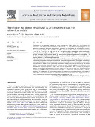
- 1. Production of pea protein concentrates by ultrafiltration: Influence of hollow-fibre module Martin Mondor ⁎, Olga Tuyishime, Hélène Drolet Food Research and Development Centre, Agriculture and Agri-Food Canada, Saint-Hyacinthe, Quebec, Canada J2S 8E3 a b s t r a c ta r t i c l e i n f o Article history: Received 13 October 2011 Accepted 5 February 2012 Editor Proof Receive Date 2 March 2012 Keywords: Fouling Hollow-fibre Lumen diameter Pea protein concentrate Ultrafiltration The purpose of this work was to study the impact of using three 50 kDa hollow-fibre ultrafiltration (UF) membranes with different fibre lumen internal diameter (0.5, 1.1 and 1.5 mm) on the UF permeate flux and on the composition of the final concentrate. In addition to the difference in the internal lumen diameter, it was observed that the three modules also differ in terms of their intrinsic membrane resistance (1.40×10¹² m−1 , 1.69×10¹² m−1 and 3.49×10¹² m−1 for the 0.5, 1.1 and 1.5 mm diameter module, respectively). Hydraulic resistances and permeate fluxes measurement indicated that the impact of fouling is increasing with a decrease in the fibre lumen diameter. Despite the high degree of fouling observed for the 0.5 mm module, it is for this module that the highest mean permeate flux was observed. Finally, no difference in concentrate composi- tion was observed as a function of the module used. Industrial relevance: The potential of ultrafiltration with 50 kDa membranes for the production of pea protein concentrates/isolates with improved nutritional and functional properties, when compared to concentrates/ isolates produced by conventional isoelectric precipitation has already been demonstrated. However, even for a given molecular weight cut-off and module configuration, different modules are available on the market and it is conceivable that their performance in terms of permeate flux will vary due to the difference in the hydrodynamic conditions observed in each of these modules. Despite of that, there is currently no information available on the subject. So, the purpose of this work was to study the impact of using three 50 kDa hollow-fibre membranes with different fibre lumen internal diameter (0.5, 1.1 and 1.5 mm) on the permeate flux and com- position of the final product. The generated information will help to improve our understanding of the impact of hollow-fibre lumen internal diameter on both aforementioned parameters and is a first step toward the suc- cessful transfer of the technology from the pilot plant to the industrial scale. Crown Copyright © 2012 Published by Elsevier Ltd. All rights reserved. 1. Introduction Pea is an important grain legume which serves as an important protein source for human consumption and animal feeding, and consequently is widely grown in the world. Peas are consumed both as fresh immature seeds as well as dry seeds. The latter are mostly consumed as whole seeds after cooking. The pea protein fraction can be extracted and further purified into a protein concentrate. Protein concentrates have been produced commercially from dry peas, although the primary limitation to sales of these products has been the difficulty in competing with the well-established, versatile soy protein ingredients that dominate the food protein ingredient market (Owusu-Ansah & Mc Curdy, 1991). The most widely used procedure to prepare pea protein concentrates is the isoelectric precipitation (Fuhrmeister & Meuser, 2003; Makri, Papalamprou, & Doxastakis, 2005; Swanson, 1990). It consists in extracting proteins from the pea flour through solubilization in water at a temperature varying between 30 and 50 °C at an alkaline pH of 8 to 10. Following the protein extraction step, the insoluble matter is removed by centri- fugation, and then the proteins are precipitated by adding acid until the isoelectric point (~pH 4.5) is reached. The curd is recuperated by a second centrifugation step, it is washed to remove non-protein soluble matter, neutralized (pH 7) and spray dried to obtain a protein concentrate. An alternative method for recovering the pea proteins from the alkaline extract is ultrafiltration (UF) (Boye et al., 2010; Fredrikson, Biot, Alminger, Carlsson, & Sandberg, 2001; Fuhrmeister & Meuser, 2003; Makri et al., 2005; Taherian et al., 2011). The chief advantages of UF are its mild operating conditions and a higher yield than the conventional isoelectric precipitation approach achieved through higher retention of proteins including the ones that cannot be precip- itated (whey-like proteins). Most of these proteins are lost in the conventional process because they do not precipitate out at a pH of 4.5. Under some processing conditions UF is also an effective method to reduce the quantities of some undesirable constituents, such as phytic acid and oligosaccharides, to a low level. A few studies that report on the use of ultrafiltration (UF) for the production of pea Innovative Food Science and Emerging Technologies 14 (2012) 135–138 ⁎ Corresponding author. Tel.: +1 450 768 3297; fax: +1 450 773 8461. E-mail address: martin.mondor@agr.gc.ca (M. Mondor). 1466-8564/$ – see front matter. Crown Copyright © 2012 Published by Elsevier Ltd. All rights reserved. doi:10.1016/j.ifset.2012.02.003 Contents lists available at SciVerse ScienceDirect Innovative Food Science and Emerging Technologies journal homepage: www.elsevier.com/locate/ifset
- 2. protein concentrate are found in the literature. However, except for the work of Fuhrmeister and Meuser (2003), who have tested miniature plate modules with different molecular weight cut-off, no detailed study were carried out concerning the effect of the UF module on the UF permeate flux and composition of the final concentrate. In particular, no work was done to establish the effect of hollow-fibre lumen diameter on the two aforementioned parameters. Therefore, the objective of the present work was to study the impact of using three 50 kDa hollow- fibre membranes with different fibre lumen diameter i.e. 0.5, 1.1 and 1.5 mm internal diameter, on the permeate flux during UF and on the composition of the final products. 2. Materials and methods 2.1. Pea protein extract Pea protein extract (PPE) was prepared from pea flour, which was obtained by grinding previously cleaned dry peas (Clic International inc., Montreal, Quebec) using a Quadro mill grinder (Quadro Engineering inc., Waterloo, Ontario). The pea flour (333 g for the 2% PPE) was extracted in 5 L of water under vigorous stirring. The mixture was brought to a temperature of 50 °C and the flour was rehydrated for 30 minutes, then the pH was adjusted to 9 using a 2 M NaOH solution. Once the pH was stabilized, additional extraction was carried out for 45 minutes, with correction of pH if required. Once the extraction procedure was completed, the insoluble constituents were separated from the soluble proteins by centrifugation at 4000×g for 20 minutes. The supernatant (PPE) was recuperated and was immediately processed by UF. 2.2. Ultrafiltration A laboratory-scale UF system (Amicon, Model DC10L) was used to purify the pH 9 pea extracts. Three 50 kDa hollow-fibre membranes (HF2-20-PM50; HF1-43-PM50 and HF1-60-PM50; Chalinox, St-Hyacinthe, Quebec) with different fibre lumen diameter i.e. 0.5, 1.1 and 1.5 mm internal diameter, respectively, were used; they had a total surface area of 0.19, 0.09 and 0.09 m2 , respectively. The solution was fed into the fibres at a flow rate of 0.13 L/s, which corre- sponds to a shear rate of 35450, 14650 and 7880 s−1 for the hollow- fibre membranes with 0.5, 1.1 and 1.5 mm internal lumen diameter, respectively. The system was operated at room temperature and the transmembrane pressure was set to 15 PSI. Operating transmembrane pressure was chosen to be slightly below the critical transmembrane pressure of 17.5 PSI which was determined by measuring the permeate flux at various transmembrane pressures ranging between 9 and 23 PSI. The critical transmembrane pressure is the one for which the permeate flux which is initially proportional to the applied ΔP becomes no longer a function of the applied ΔP. This behavior is related to the cake forma- tion at the membrane surface. All UF experiments were conducted by applying a volume concentration ratio of 4 (VCR=V0/Vuf, where V0 is the starting volume and Vuf is the final volume of retentate) to a 2% PPE. Evolution of the different hydraulic resistances as a function of VCR was followed using Darcy's law. For the clean membrane, its resistance was evaluated from data for the water flux, measured via timed collection, as a function of the applied pressure. Clean membrane resistance was estimated using the following equation: Jwo ¼ ΔP μw Rm ð1Þ where Jwo is the water flux, ΔP is the transmembrane pressure, μw is the water viscosity and Rm is the clean membrane resistance. The test enabled the determination of clean membrane resistance from the slope of a graph of the water flux vs transmembrane pressure. During concentrate production, UF of the pea extract caused irreversible fouling and cake formation (also known as reversible fouling). Global resistance changes over time and is no longer solely dependent on the membrane. Resistance during UF becomes equal to Rm +Ri +Rc where Rm is the membrane resistance, Ri is the resistance due to irreversible fouling and Rc is the resistance due to cake formation, it can be estimated from Eq. (2): RG ¼ Rm þ Ri þ Rc ¼ ΔP μp Jf p ð2Þ where μp is the permeate viscosity and Jp f is the final permeate flux. At the completion of the UF step, the system was carefully emptied and rinsed with double distilled water to remove any deposited protein. The pea protein concentrate was rapidly frozen before being lyophilized and stored at 4 °C until analyzed. The system was filled with double distilled water and the flux was re-evaluated. Membrane resistance was estimated from Eq. (1), where the initial water flux, Jwo, was replaced by the final water flux, Jw. Membrane resistance was reported as the sum of the clean membrane resistance+resistance due to irreversible fouling. The above-mentioned approach leads to the estimation of the different individual hydraulic resistances. It was assumed that the irreversible fouling took place very quickly during the first minutes of UF and then remained constant throughout the concentration step. 2.3. Composition analysis Protein content of the flour, extracts and concentrates was deter- mined by combustion nitrogen analysis with a LECO Model FP-428 CNA analyzer (LECO corp., Saint Joseph, MI) calibrated with EDTA. The protein content was expressed as total nitrogen X 6.25. Moisture and ash contents were respectively determined using methods derived from AOAC methods 925.09 and 923.03 (AOAC, 1995). Moisture content of the different samples was measured by drying overnight a known quantity of each sample in a vacuum oven (Fisher Scientific ISO- TEMP) at a pressure of 0.8 mm Hg and a temperature of 92 °C. After a cooling period in a dessicator until a constant weight is obtained, the samples were weighted and the moisture content was calculated based on initial weight of the wet samples. The dry samples were then ashed in an oven at 550 °C for 16 h. After a cooling period in a dessicator until a constant weight is obtained, the samples were weighted and the percent ash was calculated based on the weight of the dry samples. The ash residues were then dissolved in 1.86 M HCl solution, and portions were used for the phytic acid determination (estimated as total phos- phorous) by using the phosphovanadomolybdate spectrophotometric method at 400 nm (Ali, Ippersiel, Lamarche, & Mondor, 2010; Leatherhead Food Research Association, 1987; Skorepova & Moresoli, 2007; Taherian et al., 2011). The method is based on the formation of ammonium phospho-vanado-molybdate, which absorbs in the visible region of the electromagnetic spectrum. A monobasic potassium phos- phate solution was used as standard. 2.4. Statistical analyses UF experiments were carried out in triplicate for each of the three 50 kDa modules. Each of the flours and extracts used for the afore- mentioned experiments, as well as the concentrates produced, was characterized for their composition, in duplicate. The results for the hydraulic resistances, permeate fluxes and composition are reported as the average values. A t-test as described by Montgomery (1991) was performed to establish if the hollow-fibre lumen internal diameter had an impact on the composition of the concentrates produced. A difference of p less than 0.05 was considered to be significant. 136 M. Mondor et al. / Innovative Food Science and Emerging Technologies 14 (2012) 135–138
- 3. 3. Results and discussion 3.1. Hydraulic resistances The clean membrane resistance for each of the three modules is: 1.40×10¹² m−1 , 1.69×10¹² m−1 and 3.49×10¹² m−1 for the 0.5, 1.1 and 1.5 mm diameter module, respectively. Since all three modules have a molecular weight cut-off of 50 kDa, it is reasonable to assume that the difference in resistance is due to a difference in fibre thickness. In fact, a combination of a thin fibre and a small diameter will yield a fibre of sufficient solidity, but a larger diameter will require a larger thickness to ensure that the fibre is solid enough. Concerning the irreversible resistance, it is 2.65×10¹² m−1 , 2.71×10¹² m−1 and 4.11×10¹² m−1 for the 0.5, 1.1 and 1.5 mm diameter module, respectively. The cake resistance is presented for each module as a function of VCR in Fig. 1. At the start of the UF, the contribution of the cake resistance to the global resistance is theoretically 0% since cake formation has not yet occurred. For the 0.5 mm diameter module, the cake resistance vary between 2.88×10¹² m−1 and 8.63×10¹² m−1 , which corresponds to a contribution to the global resistance varying between 41.5% and 68.0%, respectively. Therefore, during the UF with the 0.5 mm module, cake formation is the greatest contributor to the increase in global resistance. The 1.1 mm module behaves in the same way as the 0.5 mm module. However, the cake resistance is more important at the start of the UF for the 1.1 mm module than for the 0.5 mm module (Fig. 1). Its cake resistance vary between 4.27×10¹² m−1 and 8.63×10¹² m−1 , which corresponds to a contribution to the global resistance in the order of 49.3% and 66.3%, respectively. For the 1.5 mm module, the variation in the cake resistance is less important than for the other module; it varied between 3.44×10¹² m−1 and 5.56×10¹² m−1 , which corresponds to a contribution to the global resistance of 31.2% and 42.3%, respectively. It is for this module that the contribution of the cake resistance to the global resistance is the lowest. 3.2. Permeate fluxes The permeate flux is related to the cake resistance through Darcy's law (Eqs. (1) and (2)). An increase in the cake resistance will thus result in a decrease of the permeate flux. As expected, from the results reported for the cake resistance, a decrease in permeate flux was observed for all the modules (Fig. 2). The greatest decrease was observed for the 0.5 mm module: the initial permeate flux was 1.99×10⁻⁵ m/s and the final flux was 1.09×10⁻⁵ m/s, which repre- sents 54.8% of the initial flux. For the 1.1 mm module, the decrease was lower; the initial flux was 1.59×10⁻⁵ m/s and the final flux was 1.07×10⁻⁵ m/s; the final flux represents 67.3% of the initial flux. For the 1.5 mm module, the flux decrease was the lowest, the initial flux being 1.22×10⁻⁵ m/s and the final flux 1.10×10⁻⁵ m/s, which represents 90.2% of the initial flux. These results were confirmed by the slopes estimated for the start of each filtration. In fact, for the 0.5 mm module, the slope was the steepest (−4.44×10⁻⁶ ), the 1.1 mm module had an intermediate slope (−2.57×10⁻⁶ ) and the 1.5 mm module had the shallowest slope (−0.69×10⁻⁶ ). 3.3. Influence of fibre diameter and membrane resistance on the UF performance In this study, two parameters varied as a function of the modules i.e. the fibre lumen internal diameter and the intrinsic membrane resistance (due to membrane thickness). Since the fibre internal diameter was different for the three modules, this resulted in different shear rates within the fibres i.e. 35450 s−1 in the 0.5 mm module, 14650 s−1 in the 1.1 mm module, and 7880 s−1 in the 1.5 mm module. Significant shear would be expected to increase the back- transport of particles from the membrane surface toward the bulk solution through its effect on the tangential force, shear-induced diffusion and inertial lift, and consequently minimize cake formation (Belfort, Davis, & Zydney, 1994; Kramadhati, Mondor, & Moresoli, 2002; Stamatakis & Tien, 1993). Since the 0.5 mm module is the module with the most significant shear, we would expect to observe the least reversible fouling, yet here it is the contrary. Membrane resistance was the second parameter. It is well known that the initial permeate flux and that the permeate flux during UF are linked to the membrane resistance by Darcy's law (Eqs. (1) and (2), respectively). From Darcy's law, it is expected that an increase in the membrane resistance will result in a decrease in the permeate flux. Our results are in agreement with these predictions since the 0.5 mm module which had the lowest membrane resistance (1.40×10¹² m−1 ), had the highest initial flux (1.99×10⁻⁵ m/s). As well, the 1.1 mm module, which had an intermediate resistance (1.69×10¹² m−1 ), had an initial flux that was also intermediate (1.59×10⁻⁵ m/s), and the 1.5 mm module, which had the highest resistance (3.49×10¹² m−1 ), had the lowest initial flux (1.22×10⁻⁵ m/s). As previously discussed (Belfort et al., 1994; Kramadhati et al., 2002; Stamatakis & Tien, 1993), the force responsible for the transport of particles from the bulk solution toward the membrane surface (drag force) will increase with an increase in the permeate flux. As a result if the drag force is predominant over the back-transport of particles away from the membrane surface, we would expect the most significant cake formation for the 0.5 mm 0,00E+00 1,00E+12 2,00E+12 3,00E+12 4,00E+12 5,00E+12 6,00E+12 7,00E+12 8,00E+12 9,00E+12 1,00E+13 1,00 1,50 2,00 2,50 3,00 3,50 4,00 4,50 Cakeresistance(m-1) VCR Fig. 1. Evolution of the cake resistance as a function of the VCR. ◊: 0.5 mm diameter; ■: 1.1 mm diameter, and ▲: 1.5 mm diameter. 8,0E-06 1,2E-05 1,6E-05 2,0E-05 2,4E-05 1,00 1,50 2,00 2,50 3,00 3,50 4,00 4,50 Flux(m/s) VCR Fig. 2. Evolution of the permeate flux as a function of the VCR. ◊: 0.5 mm diameter; ■: 1.1 mm diameter, and ▲: 1.5 mm diameter. 137M. Mondor et al. / Innovative Food Science and Emerging Technologies 14 (2012) 135–138
- 4. diameter module, followed by the 1.1 mm diameter module and by the 1.5 mm diameter module. Therefore, after studying the two parameters that differ in the three modules, we can say that for the conditions studied in the present work, membrane resistance has a greater impact on permeate flux than the fibre internal diameter. However, despite the significant reversible fouling observed for the 0.5 mm module, the average permeate flux nevertheless remains higher when this module is used. The average flux was 1.64×10⁻⁵ m/s for the 0.5 mm module, 1.38×10⁻⁵ m/s for the 1.1 mm module, and 1.16×10⁻⁵ m/s for the 1.5 mm module. It also worth to mention that the flux of these three modules tends toward a constant flux of approximately 1.10×10⁻⁵ m/s. Since the transmembrane pressure and the viscosity of the permeate are the same for all experiments, the permeate flux is mainly function of the global resistance. In this case, the global resistance of the three modules tends toward a value of 1.27×10¹³ m−1 . 3.4. Concentrates composition The protein, ash and phytic acid (estimated as total phosphorous) contents of the concentrates are presented in Table 1. As previously stated, a t-test was performed to determine whether the results obtained for the different modules were statistically different; the test did not enable us to conclude that the results were different. In fact, these three modules had the same molecular weight cut-off; they differ only in terms of fibre lumen internal diameter and membrane resistance. These two parameters will have an effect on membrane foul- ing, however, given the fact that our products were concentrated to the same VCR it is not surprising that the same quantity of soluble minerals and sugars has been removed. It is possible to conclude that the cake formed at the membrane surface does not act as a barrier to the analysed constituents. 4. Conclusion This study on UF of pea proteins showed that there are several parameters involved and that their impact varies depending on the module used. Significant fouling was observed when the extract was filtered using a 0.5 mm module: at the end of the filtration, there was a 45.2% decrease in the initial flux and significant cake formation. When the solution was ultrafiltered with a 1.1 mm module, the reduction in flux was smaller, i.e. 32.7%. With a 1.5 mm module, significant fouling was observed at the start, which is attributable to irreversible fouling, and the flux remained more constant during UF with only a reduction in flux of 9.8%. However, the highest mean permeate flux was obtained with the 0.5 mm diameter module, followed by the 1.1 mm diameter module and the 1.5 mm module. Therefore, despite a high degree of fouling, the productivity of the 0.5 mm module remains higher than for the other two modules. No difference in concentrate composition was observed; the protein, mineral and phytic acid (estimated as total phosphorous) composi- tions were identical. These results are attributable to the fact that the majority of the compounds to be removed are in soluble form. Acknowledgements The financial support of Agriculture and Agri-Food Canada is gratefully acknowledged. References Ali, F., Ippersiel, D., Lamarche, F., & Mondor, M. (2010). Characterization of low-phytate soy protein isolates produced by membrane technologies. Innovative Food Science and Emerging Technologies, 11, 162–168. AOAC International (1995). Methods 925.09 and 923.03. In P. Cunniff (Ed.), Official methods of analysis (16th ed.). . Washington: AOAC. Belfort, G., Davis, R. H., & Zydney, A. L. (1994). The behaviour of suspensions and mac- romolecular solutions in crossflow microfiltration. Journal of Membrane Science, 96, 1–58. Boye, J. I., Aksay, S., Roufik, S., Ribéreau, S., Mondor, M., Farnworth, E., et al. (2010). Comparison of the functional properties of pea, chickpea, and lentil protein con- centrates processed using ultrafiltration and isoelectric precipitation techniques. Food Research International, 43, 537–546. Fredrikson, M., Biot, P., Alminger, M. L., Carlsson, N. -G., & Sandberg, A. -S. (2001). Pro- duction process for high-quality pea-protein isolate with low content of oligosac- charides and phytate. Journal of Agricultural and Food Chemistry, 49, 1208–1212. Fuhrmeister, H., & Meuser, F. (2003). Impact of processing on functional properties of protein products from wrinkled peas. Journal of Food Engineering, 56, 119–129. Kramadhati, N. N., Mondor, M., & Moresoli, C. (2002). Evaluation of the shear-induced diffusion model for the microfiltration of polydisperse feed suspension. Separation and Purification Technology, 27, 11–24. Leatherhead Food Research Association (1987). Method 2: Determination of total phosphorus (phosphor-vanado-molybdate colorimetric method). Analytical methods manual 2nd edition. Leatherhead, England: Leatherhead Food Research Association. Makri, E., Papalamprou, E., & Doxastakis, G. (2005). Study of functional properties of seed storage proteins from indigenous European legume crops (lupin, pea, broad bean) in admixture with polysaccharides. Food Hydrocolloids, 19, 583–594. Montgomery, D. C. (1991). Design and analysis of experiments. (3rd ed.). New York: John Wiley and Sons. Owusu-Ansah, Y. J., & Mc Curdy, S. M. (1991). Pea proteins: A review of chemistry, technology of production, and utilization. Food Reviews Internationals, 7(1), 103–134. Skorepova, J., & Moresoli, C. (2007). Carbohydrate and mineral removal during the pro- duction of low-phytate soy protein isolate by combined electroacidification and high shear tangential flow ultrafiltration. Journal of Agriculture and Food Chemistry, 55, 5645–5652. Stamatakis, K., & Tien, C. (1993). A simple model of cross-flow filtration based on par- ticle adhesion. AICHE Journal, 39(8), 1292–1302. Swanson, B. G. (1990). Pea and lentil protein extraction and functionality. Journal of the American Oil Chemists' Society, 67(5), 276–280. Taherian, A. R., Mondor, M., Labranche, J., Drolet, H., Ippersiel, D., & Lamarche, F. (2011). Comparative study of functional properties of commercial and membrane processed yellow pea protein isolates. Food Research International, 44, 2505–2514. Table 1 Protein, ash and phosphorus contents of the concentrates. Module 0.5 Module 1.1 Module 1.5 Protein content (%) Flour 25.2±0.2 25.2±0.2 25.2±0.2 Extract 62.8±1.4 63.1±0.8 63.3±0.6 Isolate 83.8±0.6 83.0±0.7 81.8±0.6 Ash content (%) Flour 3.8±0.0 3.8±0.0 3.8±0.0 Extract 9.7±0.1 9.5±0.2 9.5±0.1 Isolate 7.0±0.1 7.0±0.0 7.0±0.0 Phosphorus content (%) Flour 0.5±0.0 0.5±0.0 0.5±0.0 Extract 2.3±0.3 2.5±0.2 2.4±0.1 Isolate 1.7±0.1 1.8±0.1 1.7±0.0 138 M. Mondor et al. / Innovative Food Science and Emerging Technologies 14 (2012) 135–138