SlideShare ist ein Scribd-Unternehmen logo
1 von 9
Downloaden Sie, um offline zu lesen
48th AIAA Aerospace Sciences Meeting Including the New Horizons Forum and Aerospace Exposition                                 AIAA 2010-273
4 - 7 January 2010, Orlando, Florida


                          Noise and Flowfield Characteristics of a Supersonic Jet
                                    Impinging on a Porous Surface

                                                           Alex Wiley 1, Rajan Kumar 2 and Farrukh Alvi 3
                                                           Florida Center for Advanced Aero-Propulsion
                                                       FAMU-FSU College of Engineering, Tallahassee, FL, 32310

                                                                            Isaac Choutapalli 4
                                                        University of Texas - Pan American, Edinburg, TX - 78539


                                Control of the highly resonant flowfield associated with supersonic impinging jet has
                            been experimentally investigated. Measurements were made in the supersonic impinging jet
                            facility at AAPL for a Mach 1.5 ideally expanded jet. Measurements included unsteady
                            pressures on the lift plate, acoustic measurements in the nearfield and beneath the
                            impingement plane and velocity measurements using PIV. Results show that both passive
                            control using porous surface and active control with high momentum microjet injection are
                            effective in reducing nearfield noise and flow unsteadiness over a range of geometrical
                            parameters, however, the type of noise reduction achieved by the two control techniques is
                            different. The passive control reduces broadband noise whereas microjet injection
                            attenuates high amplitude impinging tones. The hybrid control, a combination of two control
                            methods reduces both broadband and high amplitude impinging tones and surprisingly its
                            effectiveness is more that the additive affect of the two control techniques.


                                                                                         I. Introduction
                         S UPERSONIC impinging jets have received considerable attention in the past because of their importance
                           in a wide range of applications from the Short/Vertical Take off Landing (S/VTOL) aircraft1-5 to the
                cooling of electronics6, and more recently in fuel cell applications7. The flow field of supersonic impinging jets is
                known to be highly unsteady especially in an S/VTOL aircraft configuration. This can have adverse effects such as
                high noise levels, unsteady acoustic loads and sonic fatigue on the aircraft and surrounding structures, ground
                erosion, ingestion of hot gases into the engine nacelle and lift loss of the aircraft. On a carrier deck, the aircraft
                exhaust impinges on the deflector plate and produces high noise levels and make the deck environment highly noisy
                and cause a serious health concern
                to the personnel working on the
                deck. It is now well known that the
                highly unsteady behavior of the
                impinging jets is due to a feedback
                loop between the flow and acoustic
                fields; a schematic of which is
                shown in Fig. 1. Beginning at the
                nozzle lip, a small instability in the
                thin shear layer grows into a large
                scale vortical structure as it
                convects downstream towards the
                ground. Upon hitting the ground, a      Figure 1. A schematic of feedback loop associated with impinging jets

                     1
                       Research Assistant, Department of Mechanical Engineering, AIAA Student Member
                     2
                       Research Scientist, Department of Mechanical Engineering, AIAA Member
                     3
                       Professor, Department of Mechanical Engineering, AIAA Associate Fellow
                     4
                       Assistant Professor, Department of Mechanical Engineering, AIAA Member
                                                                           1

                                                             American Institute of Aeronautics and Astronautics


Copyright © 2010 by the authors. Published by the American Institute of Aeronautics and Astronautics, Inc., with permission.
strong acoustic wave reflects and propagates through ambient surroundings. Once it reaches the nozzle lip, it
disrupts the thin shear layer which begins a new cycle thereby completing the feedback loop.
    Although a substantial amount of research has been carried out in the past on supersonic impinging jets and its
control using various passive and active control methods8-15, the high noise levels and flow field unsteadiness is still
a cause of concern. Most of the control methods employed in the past either needed modifications to the aircraft
nozzle or manipulation of shear layer near the nozzle exit and were therefore impractical or less effective. For
example, Elavarsan et al.10 attenuated the feedback loop by placing a circular plate near the nozzle exit, achieving a
reduction in the near-field OASPL and reasonable lift recovery. Sheplak and Spina11, with the help of high speed co-
flow, shielded the primary jet from the acoustic field. Shih et al.12 successfully suppressed screech tones of non-
ideally expanded jets using counter-flow at the nozzle exit. A recent approach to suppress the feedback mechanism
of supersonic impinging jets using an array of high momentum microjets appropriately placed near the nozzle exit
has shown highly promising results13-15. This control-on-demand technique has many advantages over traditional
passive and active control methods and has proven to be successful over a range of geometric and flow conditions.
    The focus of the present study is a technique of using a porous surface just above the ground plane to achieve
noise reduction as well as reduction in the flow field unsteadiness. We have also investigated a hybrid control, a
combination of active control, based on microjets, near the nozzle exit and a passive control such as a porous surface
near the ground plane. The concept of porous impinging surface at low speed axisymmetric and planner jets was
studied by Webb and Castro16 and Cant et al.17, respectively. Murray and Seiner18 performed acoustic measurements
of a sonic jet impinging on a ground, with and without the presence of a porous surface but very little is known
about their results. In this paper, we present a detailed experimental investigation including the unsteady pressure,
near-field acoustic and whole field velocity measurements using particle image velocimetry.

                                               II. Experimental Setup
    A. STOVL Facility
    The experiments were carried out at the STOVL supersonic jet facility of the Advanced Aero-Propulsion
Laboratory (AAPL) located at the Florida State University. This facility is mainly used to study jet-induced
phenomenon on STOVL aircraft during hover. It is capable of running single and multiple jets at design or off-
design conditions up to M = 2.2. In order to simulate different aircraft to ground plane distances, the ground plate is
mounted on a hydraulic lift and can be moved up and down. A high pressure compressed air (~160 bars) is stored in
large storage tanks (10 m3) and is used to drive the
facility. The measurements were made at ideally-
expanded conditions for a Mach 1.5 jet issuing from a
converging-diverging axisymmetric nozzle. The design
Mach number of the nozzle was 1.5 and was operated at
Nozzle Pressure Ratio (NPR, where NPR = stagnation
pressure/ambient pressure) of 3.7. The test Reynolds
number based on exit velocity and nozzle diameter of the
jet was 7 x 10⁵. The stagnation temperature of the jet was
varied from 300K to 420K, corresponding to a
temperature ratio, TR =1.0 and 1.4 (where, TR =
stagnation temperature / ambient temperature)
representing cold and hot conditions, respectively
(though only results from TR=1.0 will be discussed in
this article). The throat and exit diameters (d, de) of the
nozzle are 2.54 cm and 2.75 cm respectively. The
diverging section of the nozzle is a straight-walled with
3° divergence angle from the throat to the nozzle exit. A
circular plate of diameter 25.4 cm (= 10d) was flush
mounted with the nozzle exit. This plate, henceforth
referred as lift plate, represents a generic aircraft
planform and has a central hole, equal to the nozzle exit
diameter, through which the jet is issued. For the            Figure 2. A Schematic of the experimental setup
purpose of this study a porous surface of porosity β = 0.29 (essentially a screen of uniform porosity) and
dimensions 11d x 11d, was placed between the nozzle exit and the ground plane. The distance between the
                                                             2

                                   American Institute of Aeronautics and Astronautics
ground and the porous surface L was varied (L/d = 0.5 − 1.5) using spacers placed at the corners of the surface. A
photograph of the facility and test model used in present experiments is shown in Fig. 2. A total of sixteen microjets
were flush mounted circumferentially on the lift plate around the main jet to implement the active flow control. The
jets are issued using 400 µm diameter stainless steel tubes mounted at an inclination of 60° with respect to the main
jet axis. The supply for the microjets was provided from compressed nitrogen cylinder through a plenum chamber.
The microjets were operated at a pressure of 100 psia and the combined mass flux from all the microjets was less
than 0.5% of the primary jet mass flux.

   B. Measurements and Instrumentation

    1) Acoustic and Unsteady Pressure Measurements
     Acoustic and unsteady pressure measurements were taken at four locations as shown in Fig. 3. Nearfield
acoustics were measured
using a microphone (B& K
Type 4939 coupled with
Type      2670     preamplifier
powered       using a Nexus
Conditioning Amplifier Type
2690) placed at r/d = 15
(where r is the radial
distance      from the       jet
centerline) in the nozzle exit
plane.     Noise transmission
through the ground plane was
measured using a second
microphone placed at y/d = 5
below the impingement plate.
This      microphone        was
shielded from ambient and
reflected noise using acoustic          a) Microphone locations              b) Pressure Transducer locations
insulation on all nearby hard          Figure 3. A photograph of experimental setup and measurement locations
surfaces. Additionally, two
±5psid Kulites were flush-mounted with the lift plate at
r/d=2 and r/d = 3 to measure the unsteady pressure loads
experienced by an aircraft in hover-mode. Signals were
filtered at 30kHz using two Stanford Research Systems
SR640 Dual           Low-Pass       Filters     before being
simultaneously sampled at 70kHz. Processing was done
offline using MATLAB® codes.
    2) Particle Image velocimetry (PIV) Measurements
    Based on the unsteady pressure measurements, PIV
measurements were also performed for select cases. Figure
4 shows the experimental setup. A double-pulsed Nd.YAG
laser from Spectra-Physics with a maximum beam intensity
of ~ 400 mJ/pulse was used for illumination of the flow
field. The beam is redirected from the laser via two 45o
mirrors to the height of the region of interest. From there it
passes through two convex spherical mirrors of
approximately the same focal length to concentrate the
beam. The beam then passes through a convex negative
cylindrical lens to spread the beam in one direction, thereby
creating a laser “sheet” (see Fig. 4). Extra care was taken in
seeding and laser sheet alignment in the cases where a          Figure 4. Particle image velocimetry setup
porous surface was present. Being that the region of
interest was between the porous surface and the ground, a trade-off had to be made in which the better illumination
                                                             3

                                  American Institute of Aeronautics and Astronautics
with less reflections was attained under the porous surface. Prior to aligning the sheet-forming optics, both laser
beams were aligned to ensure consistent illumination in the centerline plane of the jet.
    The main jet was seeded using a modified nebulizer while the ambient air was seeded using a Rosco® fog
machine to prevent biasing of the shear layer data on the high-speed side of the jet (both used Rosco fog fluid).
Approximating the main jet at 450m/s, image pairs were recorded 1.25 µs apart to best match a particle
displacement of about 6 pixels which is optimal for the PIV algorithm used. The image pairs were captured at
15Hz using a Kodak ES 1.0 Megaplus camera with a resolution of approximately 150pixels/inch. 1000 image
pairs were recorded for a given condition to resolve both the mean velocities and turbulence statistics of the flow.
Afterwards, the image pairs acquired were processed using Provision II software from IDT.
    3) Measurement Uncertainty
    The stagnation pressure (Po) and temperature (To) were measured in the settling chamber near the nozzle. The
pressure was measured using an Omegadyne PX219-200A5V pressure transducer with an accuracy of ± 0.5psia.
Microjet total pressure (Pmj) was measured in a similar fashion using an Omegadyne PX303-200G5V transducer
with an experimental uncertainty of ± 0.5psig. To is monitored using a K-Type thermocouple, the signal of which is
amplified using an Analog Devices AD595 monolithic thermocouple amplifier. The uncertainty of the measurement
is ± 1oC. Both Kulites used to measure unsteady pressure loads were Model No. XCS-062-5D which have a
measurement uncertainty of ± 0.0125psid. The microphones used for acoustic measurements were both Bruel &
Kjaer Type 4939, and the uncertainty of which is ± 1dB. Prior to the experiments, each pressure transducer was
calibrated using a Druck DPI 605 calibrator over the full-scale range of the transducer. Microphone corrections
were calibrated using a Bruel & Kjaer 4220 Pistonphone which generates 124dB at 250Hz.

                                            III.   Experimental Results
    A. Unsteady Pressure Field
    As mentioned earlier, acoustic and unsteady pressure measurements were made at four different test
configurations/conditions termed as baseline (jet impinging on a solid surface), with passive control (jet impinging
on a porous surface), with microjet control (for baseline), and finally with hybrid control (both microjet and passive
control). The tests were performed over a range of nozzle to plate distances, at a fixed value of NPR = 3.7 and TR =
1.0. In the following sections, we will first discuss the narrowband spectra obtained using FFT and then OASPL and
Prms levels.
        1. Narrowband Spectra
   Figure 5a shows the effect of passive control on the unsteady spectra as measured by the sideline microphone for
h/d = 4. The results show that there is a strong impinging tone at ~7kHz along with its harmonics in the baseline


        a) Nearfield spectra using microphone                  b) Unsteady pressure spectra on lift plate
                Figure 5. Effect of passive control on the acoustic and unsteady pressure spectra

flow at this h/d. With passive control (screen located at y/d=0.5), it appears that the impinging tone has shifted to

                                                            4

                                  American Institute of Aeronautics and Astronautics
∼5.5kHz. There does appear to be a slight reduction in the magnitude of the impinging tone (and its harmonics) and
a significant reduction (nearly 5dB) is observed in broadband levels. Very similar results are seen (Fig. 5b) for kulite
sensor located at r/d =2 on the lift plate except that the magnitude of impinging tones and associated broadband
levels are higher. The observed frequency shift in impinging tone with porous surface is somewhat expected as the
distance between the nozzle and impinging surface in reduced with passive control and we know from our previous
studies that frequency of the impinging tone is strongly dependent on nozzle-to-plate distance.
    Next in Fig. 6a we see the effect of microjet control on the nearfield microphone spectra. With microjet
injection, there is a large reduction in the impinging tone and its harmonics and a small reduction in broadband
levels. These results are very similar to those observed in earlier studies on impinging jet control using microjets
injection. These results with microjet control when compared to the passive control bring out some interesting


        a) Effect of microjet control                      b) Effect of hybrid control
                     Figure 6. Nearfield noise spectra measured using sideline microphone

features. While the overall reductions in noise for both control methods in terms of OASPL are about 4dB, the type
of noise reduction is quite different. The passive method using porous surface reduces mostly the broadband of the
noise spectra while a strong impinging tone and harmonics remain. Microjet injection, as has been observed before,
mostly reduces the impinging tone and its harmonics. Being that the two methods primarily reduce different
components of the noise spectra, a combination of the two was tested to see if their effects are additive which
would lead to even larger reductions than either control method alone. The nearfield sound spectra of such
measurements termed as hybrid control are shown in Fig. 6b. The results clearly show that the impinging tones and
their harmonics are completely eliminated and broadband levels are significantly reduced. This behavior is
representative and can be seen at all other cases of varying nozzle-to-ground distances, h/d and at all the four
measurement locations.
        2. Overall Sound Pressure Levels (OASPL)
    Figure 7 shows a comparison of the OASPL levels as a function of nozzle-to-ground distance (h/d) for different
locations of passive control (the spacing between the porous surface and the ground plane was varied from 0.5d-
1.5d). Figure 7a shows the noise measured by the nearfield microphone while Fig. 7b shows the unsteady
pressures measured at the lift-plate using kulite at r/d = 2. In general, the OASPL levels are reduced with
passive control but its effectiveness depend upon the spacing between porous surface to ground plane (y/d) and
nozzle to ground plane distance (h/d). Figure 8 shows a comparison of effectiveness of different control methods in
reducing nearfield noise and unsteady pressures. Both passive control using porous surface and active control with
microjet injection show reasonable reductions in noise levels and unsteady pressures but their combined effort in
terms of hybrid control is even more effective. It is very interesting to observe that at most of the test conditions, the
effectiveness of hybrid control is more than the additive effect of passive and microjet control.


                                                              5

                                   American Institute of Aeronautics and Astronautics
a) OASPL measured using nearfield microphone         b) Unsteady pressures on the lift plate at r/d=2
              Figure 7. Effect of passive control in reducing noise and unsteady pressures


   a) OASPL measured using nearfield microphone        b) Unsteady pressures on the lift plate at r/d=2
          Figure 8. Effect of various control methods in reducing noise and unsteady pressures

    B. Particle Image Velocimetry (PIV)
    PIV measurements were made at few select cases to map the velocity field associated with supersonic impinging
jet and its control using both passive and active control methods. PIV measurements were obtained along a
streamwise central plane at h/d = 5 for impinging jet at NPR = 3.7 and TR = 1.0 for baseline and control conditions.
First we present color contour plots of the ensemble-averaged (mean) velocity (Umean) non-dimensionalized by UJ,
the fully expanded jet velocity. Velocity vectors at selected locations are shown superimposed on the mean velocity
contour plots. Figures 9a – d show the velocity field for baseline and different control conditions. As mentioned
earlier, measurements were conducted at NPR = 3.7, corresponding to ideally expanded jet conditions. The length of
the vector represents the magnitude of velocity at each location. The velocity vectors at the nozzle exit show that for
baseline and different control cases, the jet exhibits a near top-hat velocity profile. The mean jet velocity at the exit
plane is ≈ 430 m/s, corresponding to the fully expanded jet velocity at M = 1.5. With passive control (Fig. 9b) the jet
                                                             6

                                   American Institute of Aeronautics and Astronautics
velocity downstream of the porous surface is significantly reduced. With microjet injection (Fig. 9c), there seems to
be a formation of stagnation bubble near the impingement plane at this value of h/d (=5). The appearance and
disappearance of stagnation bubble at some values of h/d with control has been noted in earlier studies as well. The
hybrid control (Fig. 9d) seems to make the jet more stable and has positive features of both passive and active
control.


   a) Baseline jet                                               b) Passive control


  c) Microjet control                                d) Hybrid control
       Figure 9. Contour plots of ensemble average (mean) streamwise velocity in the central plane
    The streamwise rms velocity Urms, a measure of flow unsteadiness is non-dimensionalized by UJ. Figures 10a-d
shows the Urms /UJ distribution for baseline and different types of flow control situations. For the baseline case (Fig.
10a), we notice that near the nozzle exit Urms peaks in the shear layer and as the jet moves downstream, the level of
flow unsteadiness increase, however downstream of potential core the highest levels of Urms exist near the centerline
of the jet. With passive control (Fig. 10b) for porous surface located at L/d = 1.5, we see that magnitude and extent
of flow unsteadiness is in general the same up to porous surface location, however, in the region beneath the
porous surface the Urms levels are much lower in magnitude and narrower in extent. Next with microjet control
(Fig. 10c), we see a small increase in Urms near the nozzle exit and then relatively lower levels up to the potential
core, beyond which the unsteadiness levels are high near the center of the jet. This initial increase and then decrease
                                                             7

                                   American Institute of Aeronautics and Astronautics
in the unsteadiness levels can be correlated to growth of the shear layer with and without microjet control. As we
know from our previous studies that with microjet control, near the nozzle exit (y/d<1) the shear layer growth is


    a) Baseline jet                                              b) Passive control


    c) Microjet control                                 d) Hybrid control
            Figure 10. Contour plots of the streamwise rms velocity measured in the central plane

more as compared to jet without control, whereas, at downstream locations (y/d>1), the jet with control spreads
lesser than without control. The relatively higher levels of flow unsteadiness near the centerline above the
impingement plane are due to oscillations in the stagnation bubble. Finally, we look at Fig. 10d in which both
microjet and porous surface control are applied. This case when compared with the baseline flow, we see that
there a significant reduction in Urms levels and extent across the entire flowfield. This significant reduction in
Urms with hybrid control agrees with the acoustic and unsteady pressure measurements discussed earlier. These
results clearly demonstrate the effectiveness of hybrid control in reducing supersonic impinging jet noise and flow
unsteadiness.

                                                 IV.    Conclusions
   Noise and flowfield characteristics of a supersonic impinging jet with a passive control using a porous surface
and an active control with microjet injection are experimentally investigated. The results show that both passive and

                                                           8

                                  American Institute of Aeronautics and Astronautics
microjet control are effective in reducing nearfield noise and flow unsteadiness over a range of geometrical
parameters, however, the type of noise reduction achieved by the two control techniques is different. The passive
control reduces broadband noise whereas microjet injection attenuates high amplitude impinging tones. A
combination of two control methods - a hybrid control reduces both broadband and high amplitude impinging tones
and surprisingly its effectiveness is more that the additive affect of the two control techniques. A maximum of 17dB
reduction is observed in unsteady pressures on the lift plate and an OASPL reduction of ~13dB is seen in the
nearfield noise with hybrid control.
   PIV measurements show that with passive control the streamwise mean velocity is significantly reduced
downstream of the porous surface and there is a presence of stagnation bubble near the impingement surface with
microjet injection. The flow unsteadiness is significantly reduced with hybrid control over the entire measurement
region which is consistent with the reductions observed in the nearfield acoustic and unsteady pressures. These
results clearly demonstrate the effectiveness of hybrid control in reducing the noise and flow unsteadiness associated
with supersonic impinging jets and makes it an attractive flow and noise control technique for STOVL aircraft.


                                                             References
    1
       Krothapalli, A., Rajkuperan, E., Alvi, F. S. and Lourenco, L., “Flow field and noise characteristics of a supersonic impinging
jet,” Journal of Fluid Mechanics, Vol. 392, 1999, pp. 155–181.
     2
       Alvi, F. S. and Iyer, K. G., “Mean and unsteady flow field properties of supersonic impinging jets with lift plates,” AIAA
Paper 99–1829, 1999.
     3
       Ho, C.-M. and Nossier, N. S., “Dynamics of an impinging jet. Part 1. The feedback phenomenon,” Journal of Fluid
Mechanics, Vol. 105, 1981.
     4
       Messersmith, N. L., “Aeroacoustics of supersonic and impinging jets”, AIAA paper 95–0509, 1995.
     5
        Tam, C. K. W. and Ahuja, K. K., “Theoretical model of discrete tone generation by impinging jets”, Journal of Fluid
Mechanics, Vol. 214, 1990, pp. 67–87
     6
       Ro, I. P., Loh, G. B., “Feasibility of using ultrasonic flexural waves as a cooling mechanism,” IEEE Transactions on
Industrial electronics, Vol. 48, No. 1, 2001
     7
       Greska, B., DeRoche, P., and Krothapalli, A., “A Novel Delivery Reactant System for PEM Fuel Cells,” Proceeding from
FuelCell2008, 2008.
     8
       Karamcheti, K., Bauer, A. B., Shields, W. L. Stegen, G. R. and Woolley, J. P., “Some features of an edge tone flow field,”
NASA SP 207, 1969, pp. 275–304.
     9
       Kweon, Y. –H., Miyazato, Y., Aoki, T., Kim, H. –D. and Setoguchi, T., “Control of supersonic jet noise using a wire device,”
Journal of Sound and Vibrations, Vol. 297, 2006, pp. 167–182.
     10
        Elavarasan, R., Krothapalli, A., Venkatakrishnan, L. and Lourenco, L., “Suppression of self-sustained oscillations in a
supersonic impinging jet”, AIAA Journal, Vol. 39, No. 12, 2001, pp. 2366–2373.
     11
       Sheplak, M. and Spina, E. F., “Control of high speed impinging-jet resonance”, AIAA Journal, Vol. 32, No. 8, 1994,
pp.1583–1588.
     12
        Shih, C., Alvi, F. S. and Washington, D., “Effects of counterflow on the Aeroacoustics properties of a supersonic jet,”
Journal of Aircraft, Vol. 36, No. 2, 1999, pp. 451–457.
     13
        Alvi, F. S., Lou, H., Shih, C., and Kumar, R., “Experimental study of physical mechanisms in the control of supersonic
impinging jets using microjets,” Journal of Fluid Mechanics, Vol. 613, 2008, pp. 55–83.
     14
        Kumar, R., Lazic, S., and Alvi, F. S., “Control of high-temperature supersonic impinging jets using microjets,” AIAA
Journal, Vol. 47, No. 12, December 2009, pp. 2800-2811.
     15
        Alvi, F. S., Shih, C., Elavarasan, R., Garg, G., and Krothapalli, A., “Control of Supersonic Impinging Jets Using
Supersonic Microjets,” AIAA Journal, Vol. 41, No. 7, 2003.
     16
         Webb, S. and Castro, I. P., “Axisymmetric jets impinging on porous walls”, Experiments in Fluids, Vol. 40, 2006, pp.
951–961.
     17
        Cant, R., Casto, I., and Walklate, P., “Plane jets impinging on porous walls”, Experiments in Fluids , Vol. 32, 2002, pp.
15–26.
     18
        Murray, N. and Seiner, J., “Acoustics of Jet Impingement on a Porous Plane,” American Physical Society, 60th Annual
Meeting of the Division of Fluid Dynamics , 2007.


                                                                   9

                                       American Institute of Aeronautics and Astronautics

Weitere ähnliche Inhalte

Ähnlich wie Noise and Flowfield Characteristics of Supersonic Jet Impinging on a Porous Surface

Role of Coherent Structures in Supersonic Jet Noise and Its Control
Role of Coherent Structures in Supersonic Jet Noise and Its ControlRole of Coherent Structures in Supersonic Jet Noise and Its Control
Role of Coherent Structures in Supersonic Jet Noise and Its Controlaswiley1
 
Density Field Measurements of a Supersonic Impinging Jet with Microjet Control
Density Field Measurements of a Supersonic Impinging Jet with Microjet ControlDensity Field Measurements of a Supersonic Impinging Jet with Microjet Control
Density Field Measurements of a Supersonic Impinging Jet with Microjet Controlaswiley1
 
Control of Resonant Flows Using High Bandwidth Mirco-Actuators
Control of Resonant Flows Using High Bandwidth Mirco-ActuatorsControl of Resonant Flows Using High Bandwidth Mirco-Actuators
Control of Resonant Flows Using High Bandwidth Mirco-Actuatorsaswiley1
 
10.1177@1077546320936510
10.1177@107754632093651010.1177@1077546320936510
10.1177@1077546320936510Jagajyoti Panda
 
Heated Jet Noise Rig
Heated Jet Noise RigHeated Jet Noise Rig
Heated Jet Noise RigPablo Mora
 
Harwood_NEEC_Poster_Final
Harwood_NEEC_Poster_FinalHarwood_NEEC_Poster_Final
Harwood_NEEC_Poster_FinalCasey Harwood
 
Effect of mainstream air velocity on velocity profile over a rough flat surface
Effect of mainstream air velocity on velocity profile over a rough flat surfaceEffect of mainstream air velocity on velocity profile over a rough flat surface
Effect of mainstream air velocity on velocity profile over a rough flat surfaceijceronline
 
Development And Implementationof High Frequency Pulsed Microjets for Active C...
Development And Implementationof High Frequency Pulsed Microjets for Active C...Development And Implementationof High Frequency Pulsed Microjets for Active C...
Development And Implementationof High Frequency Pulsed Microjets for Active C...aswiley1
 
Effects of Leading-edge Tubercles and Dimples on a Cambered Airfoil and its P...
Effects of Leading-edge Tubercles and Dimples on a Cambered Airfoil and its P...Effects of Leading-edge Tubercles and Dimples on a Cambered Airfoil and its P...
Effects of Leading-edge Tubercles and Dimples on a Cambered Airfoil and its P...IRJET Journal
 
IRJET- Aerodynamic Performance Analysis on a Wing with “M” Shaped Serrate...
IRJET-  	  Aerodynamic Performance Analysis on a Wing with “M” Shaped Serrate...IRJET-  	  Aerodynamic Performance Analysis on a Wing with “M” Shaped Serrate...
IRJET- Aerodynamic Performance Analysis on a Wing with “M” Shaped Serrate...IRJET Journal
 
6%2E2015-2384
6%2E2015-23846%2E2015-2384
6%2E2015-2384Alex Sano
 
Analysis of Ground Effect on a Symmetrical Airfoil
Analysis of Ground Effect on a Symmetrical AirfoilAnalysis of Ground Effect on a Symmetrical Airfoil
Analysis of Ground Effect on a Symmetrical AirfoilIJERA Editor
 

Ähnlich wie Noise and Flowfield Characteristics of Supersonic Jet Impinging on a Porous Surface (20)

Role of Coherent Structures in Supersonic Jet Noise and Its Control
Role of Coherent Structures in Supersonic Jet Noise and Its ControlRole of Coherent Structures in Supersonic Jet Noise and Its Control
Role of Coherent Structures in Supersonic Jet Noise and Its Control
 
Density Field Measurements of a Supersonic Impinging Jet with Microjet Control
Density Field Measurements of a Supersonic Impinging Jet with Microjet ControlDensity Field Measurements of a Supersonic Impinging Jet with Microjet Control
Density Field Measurements of a Supersonic Impinging Jet with Microjet Control
 
aiaa2007-0310
aiaa2007-0310aiaa2007-0310
aiaa2007-0310
 
Control of Resonant Flows Using High Bandwidth Mirco-Actuators
Control of Resonant Flows Using High Bandwidth Mirco-ActuatorsControl of Resonant Flows Using High Bandwidth Mirco-Actuators
Control of Resonant Flows Using High Bandwidth Mirco-Actuators
 
Co24593599
Co24593599Co24593599
Co24593599
 
10.1177@1077546320936510
10.1177@107754632093651010.1177@1077546320936510
10.1177@1077546320936510
 
Heated Jet Noise Rig
Heated Jet Noise RigHeated Jet Noise Rig
Heated Jet Noise Rig
 
Air impingement technologyfor food processing
Air impingement technologyfor food processingAir impingement technologyfor food processing
Air impingement technologyfor food processing
 
Harwood_NEEC_Poster_Final
Harwood_NEEC_Poster_FinalHarwood_NEEC_Poster_Final
Harwood_NEEC_Poster_Final
 
In3614821488
In3614821488In3614821488
In3614821488
 
Chapter 1
Chapter 1Chapter 1
Chapter 1
 
Effect of mainstream air velocity on velocity profile over a rough flat surface
Effect of mainstream air velocity on velocity profile over a rough flat surfaceEffect of mainstream air velocity on velocity profile over a rough flat surface
Effect of mainstream air velocity on velocity profile over a rough flat surface
 
Development And Implementationof High Frequency Pulsed Microjets for Active C...
Development And Implementationof High Frequency Pulsed Microjets for Active C...Development And Implementationof High Frequency Pulsed Microjets for Active C...
Development And Implementationof High Frequency Pulsed Microjets for Active C...
 
D42051929
D42051929D42051929
D42051929
 
Drag reduction using Aerospike
Drag reduction using AerospikeDrag reduction using Aerospike
Drag reduction using Aerospike
 
Effects of Leading-edge Tubercles and Dimples on a Cambered Airfoil and its P...
Effects of Leading-edge Tubercles and Dimples on a Cambered Airfoil and its P...Effects of Leading-edge Tubercles and Dimples on a Cambered Airfoil and its P...
Effects of Leading-edge Tubercles and Dimples on a Cambered Airfoil and its P...
 
IRJET- Aerodynamic Performance Analysis on a Wing with “M” Shaped Serrate...
IRJET-  	  Aerodynamic Performance Analysis on a Wing with “M” Shaped Serrate...IRJET-  	  Aerodynamic Performance Analysis on a Wing with “M” Shaped Serrate...
IRJET- Aerodynamic Performance Analysis on a Wing with “M” Shaped Serrate...
 
6%2E2015-2384
6%2E2015-23846%2E2015-2384
6%2E2015-2384
 
E012452934
E012452934E012452934
E012452934
 
Analysis of Ground Effect on a Symmetrical Airfoil
Analysis of Ground Effect on a Symmetrical AirfoilAnalysis of Ground Effect on a Symmetrical Airfoil
Analysis of Ground Effect on a Symmetrical Airfoil
 

Noise and Flowfield Characteristics of Supersonic Jet Impinging on a Porous Surface

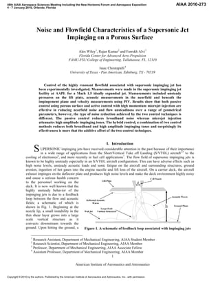
  • 1. 48th AIAA Aerospace Sciences Meeting Including the New Horizons Forum and Aerospace Exposition AIAA 2010-273 4 - 7 January 2010, Orlando, Florida Noise and Flowfield Characteristics of a Supersonic Jet Impinging on a Porous Surface Alex Wiley 1, Rajan Kumar 2 and Farrukh Alvi 3 Florida Center for Advanced Aero-Propulsion FAMU-FSU College of Engineering, Tallahassee, FL, 32310 Isaac Choutapalli 4 University of Texas - Pan American, Edinburg, TX - 78539 Control of the highly resonant flowfield associated with supersonic impinging jet has been experimentally investigated. Measurements were made in the supersonic impinging jet facility at AAPL for a Mach 1.5 ideally expanded jet. Measurements included unsteady pressures on the lift plate, acoustic measurements in the nearfield and beneath the impingement plane and velocity measurements using PIV. Results show that both passive control using porous surface and active control with high momentum microjet injection are effective in reducing nearfield noise and flow unsteadiness over a range of geometrical parameters, however, the type of noise reduction achieved by the two control techniques is different. The passive control reduces broadband noise whereas microjet injection attenuates high amplitude impinging tones. The hybrid control, a combination of two control methods reduces both broadband and high amplitude impinging tones and surprisingly its effectiveness is more that the additive affect of the two control techniques. I. Introduction S UPERSONIC impinging jets have received considerable attention in the past because of their importance in a wide range of applications from the Short/Vertical Take off Landing (S/VTOL) aircraft1-5 to the cooling of electronics6, and more recently in fuel cell applications7. The flow field of supersonic impinging jets is known to be highly unsteady especially in an S/VTOL aircraft configuration. This can have adverse effects such as high noise levels, unsteady acoustic loads and sonic fatigue on the aircraft and surrounding structures, ground erosion, ingestion of hot gases into the engine nacelle and lift loss of the aircraft. On a carrier deck, the aircraft exhaust impinges on the deflector plate and produces high noise levels and make the deck environment highly noisy and cause a serious health concern to the personnel working on the deck. It is now well known that the highly unsteady behavior of the impinging jets is due to a feedback loop between the flow and acoustic fields; a schematic of which is shown in Fig. 1. Beginning at the nozzle lip, a small instability in the thin shear layer grows into a large scale vortical structure as it convects downstream towards the ground. Upon hitting the ground, a Figure 1. A schematic of feedback loop associated with impinging jets 1 Research Assistant, Department of Mechanical Engineering, AIAA Student Member 2 Research Scientist, Department of Mechanical Engineering, AIAA Member 3 Professor, Department of Mechanical Engineering, AIAA Associate Fellow 4 Assistant Professor, Department of Mechanical Engineering, AIAA Member 1 American Institute of Aeronautics and Astronautics Copyright © 2010 by the authors. Published by the American Institute of Aeronautics and Astronautics, Inc., with permission.
  • 2. strong acoustic wave reflects and propagates through ambient surroundings. Once it reaches the nozzle lip, it disrupts the thin shear layer which begins a new cycle thereby completing the feedback loop. Although a substantial amount of research has been carried out in the past on supersonic impinging jets and its control using various passive and active control methods8-15, the high noise levels and flow field unsteadiness is still a cause of concern. Most of the control methods employed in the past either needed modifications to the aircraft nozzle or manipulation of shear layer near the nozzle exit and were therefore impractical or less effective. For example, Elavarsan et al.10 attenuated the feedback loop by placing a circular plate near the nozzle exit, achieving a reduction in the near-field OASPL and reasonable lift recovery. Sheplak and Spina11, with the help of high speed co- flow, shielded the primary jet from the acoustic field. Shih et al.12 successfully suppressed screech tones of non- ideally expanded jets using counter-flow at the nozzle exit. A recent approach to suppress the feedback mechanism of supersonic impinging jets using an array of high momentum microjets appropriately placed near the nozzle exit has shown highly promising results13-15. This control-on-demand technique has many advantages over traditional passive and active control methods and has proven to be successful over a range of geometric and flow conditions. The focus of the present study is a technique of using a porous surface just above the ground plane to achieve noise reduction as well as reduction in the flow field unsteadiness. We have also investigated a hybrid control, a combination of active control, based on microjets, near the nozzle exit and a passive control such as a porous surface near the ground plane. The concept of porous impinging surface at low speed axisymmetric and planner jets was studied by Webb and Castro16 and Cant et al.17, respectively. Murray and Seiner18 performed acoustic measurements of a sonic jet impinging on a ground, with and without the presence of a porous surface but very little is known about their results. In this paper, we present a detailed experimental investigation including the unsteady pressure, near-field acoustic and whole field velocity measurements using particle image velocimetry. II. Experimental Setup A. STOVL Facility The experiments were carried out at the STOVL supersonic jet facility of the Advanced Aero-Propulsion Laboratory (AAPL) located at the Florida State University. This facility is mainly used to study jet-induced phenomenon on STOVL aircraft during hover. It is capable of running single and multiple jets at design or off- design conditions up to M = 2.2. In order to simulate different aircraft to ground plane distances, the ground plate is mounted on a hydraulic lift and can be moved up and down. A high pressure compressed air (~160 bars) is stored in large storage tanks (10 m3) and is used to drive the facility. The measurements were made at ideally- expanded conditions for a Mach 1.5 jet issuing from a converging-diverging axisymmetric nozzle. The design Mach number of the nozzle was 1.5 and was operated at Nozzle Pressure Ratio (NPR, where NPR = stagnation pressure/ambient pressure) of 3.7. The test Reynolds number based on exit velocity and nozzle diameter of the jet was 7 x 10⁵. The stagnation temperature of the jet was varied from 300K to 420K, corresponding to a temperature ratio, TR =1.0 and 1.4 (where, TR = stagnation temperature / ambient temperature) representing cold and hot conditions, respectively (though only results from TR=1.0 will be discussed in this article). The throat and exit diameters (d, de) of the nozzle are 2.54 cm and 2.75 cm respectively. The diverging section of the nozzle is a straight-walled with 3° divergence angle from the throat to the nozzle exit. A circular plate of diameter 25.4 cm (= 10d) was flush mounted with the nozzle exit. This plate, henceforth referred as lift plate, represents a generic aircraft planform and has a central hole, equal to the nozzle exit diameter, through which the jet is issued. For the Figure 2. A Schematic of the experimental setup purpose of this study a porous surface of porosity β = 0.29 (essentially a screen of uniform porosity) and dimensions 11d x 11d, was placed between the nozzle exit and the ground plane. The distance between the 2 American Institute of Aeronautics and Astronautics
  • 3. ground and the porous surface L was varied (L/d = 0.5 − 1.5) using spacers placed at the corners of the surface. A photograph of the facility and test model used in present experiments is shown in Fig. 2. A total of sixteen microjets were flush mounted circumferentially on the lift plate around the main jet to implement the active flow control. The jets are issued using 400 µm diameter stainless steel tubes mounted at an inclination of 60° with respect to the main jet axis. The supply for the microjets was provided from compressed nitrogen cylinder through a plenum chamber. The microjets were operated at a pressure of 100 psia and the combined mass flux from all the microjets was less than 0.5% of the primary jet mass flux. B. Measurements and Instrumentation 1) Acoustic and Unsteady Pressure Measurements Acoustic and unsteady pressure measurements were taken at four locations as shown in Fig. 3. Nearfield acoustics were measured using a microphone (B& K Type 4939 coupled with Type 2670 preamplifier powered using a Nexus Conditioning Amplifier Type 2690) placed at r/d = 15 (where r is the radial distance from the jet centerline) in the nozzle exit plane. Noise transmission through the ground plane was measured using a second microphone placed at y/d = 5 below the impingement plate. This microphone was shielded from ambient and reflected noise using acoustic a) Microphone locations b) Pressure Transducer locations insulation on all nearby hard Figure 3. A photograph of experimental setup and measurement locations surfaces. Additionally, two ±5psid Kulites were flush-mounted with the lift plate at r/d=2 and r/d = 3 to measure the unsteady pressure loads experienced by an aircraft in hover-mode. Signals were filtered at 30kHz using two Stanford Research Systems SR640 Dual Low-Pass Filters before being simultaneously sampled at 70kHz. Processing was done offline using MATLAB® codes. 2) Particle Image velocimetry (PIV) Measurements Based on the unsteady pressure measurements, PIV measurements were also performed for select cases. Figure 4 shows the experimental setup. A double-pulsed Nd.YAG laser from Spectra-Physics with a maximum beam intensity of ~ 400 mJ/pulse was used for illumination of the flow field. The beam is redirected from the laser via two 45o mirrors to the height of the region of interest. From there it passes through two convex spherical mirrors of approximately the same focal length to concentrate the beam. The beam then passes through a convex negative cylindrical lens to spread the beam in one direction, thereby creating a laser “sheet” (see Fig. 4). Extra care was taken in seeding and laser sheet alignment in the cases where a Figure 4. Particle image velocimetry setup porous surface was present. Being that the region of interest was between the porous surface and the ground, a trade-off had to be made in which the better illumination 3 American Institute of Aeronautics and Astronautics
  • 4. with less reflections was attained under the porous surface. Prior to aligning the sheet-forming optics, both laser beams were aligned to ensure consistent illumination in the centerline plane of the jet. The main jet was seeded using a modified nebulizer while the ambient air was seeded using a Rosco® fog machine to prevent biasing of the shear layer data on the high-speed side of the jet (both used Rosco fog fluid). Approximating the main jet at 450m/s, image pairs were recorded 1.25 µs apart to best match a particle displacement of about 6 pixels which is optimal for the PIV algorithm used. The image pairs were captured at 15Hz using a Kodak ES 1.0 Megaplus camera with a resolution of approximately 150pixels/inch. 1000 image pairs were recorded for a given condition to resolve both the mean velocities and turbulence statistics of the flow. Afterwards, the image pairs acquired were processed using Provision II software from IDT. 3) Measurement Uncertainty The stagnation pressure (Po) and temperature (To) were measured in the settling chamber near the nozzle. The pressure was measured using an Omegadyne PX219-200A5V pressure transducer with an accuracy of ± 0.5psia. Microjet total pressure (Pmj) was measured in a similar fashion using an Omegadyne PX303-200G5V transducer with an experimental uncertainty of ± 0.5psig. To is monitored using a K-Type thermocouple, the signal of which is amplified using an Analog Devices AD595 monolithic thermocouple amplifier. The uncertainty of the measurement is ± 1oC. Both Kulites used to measure unsteady pressure loads were Model No. XCS-062-5D which have a measurement uncertainty of ± 0.0125psid. The microphones used for acoustic measurements were both Bruel & Kjaer Type 4939, and the uncertainty of which is ± 1dB. Prior to the experiments, each pressure transducer was calibrated using a Druck DPI 605 calibrator over the full-scale range of the transducer. Microphone corrections were calibrated using a Bruel & Kjaer 4220 Pistonphone which generates 124dB at 250Hz. III. Experimental Results A. Unsteady Pressure Field As mentioned earlier, acoustic and unsteady pressure measurements were made at four different test configurations/conditions termed as baseline (jet impinging on a solid surface), with passive control (jet impinging on a porous surface), with microjet control (for baseline), and finally with hybrid control (both microjet and passive control). The tests were performed over a range of nozzle to plate distances, at a fixed value of NPR = 3.7 and TR = 1.0. In the following sections, we will first discuss the narrowband spectra obtained using FFT and then OASPL and Prms levels. 1. Narrowband Spectra Figure 5a shows the effect of passive control on the unsteady spectra as measured by the sideline microphone for h/d = 4. The results show that there is a strong impinging tone at ~7kHz along with its harmonics in the baseline a) Nearfield spectra using microphone b) Unsteady pressure spectra on lift plate Figure 5. Effect of passive control on the acoustic and unsteady pressure spectra flow at this h/d. With passive control (screen located at y/d=0.5), it appears that the impinging tone has shifted to 4 American Institute of Aeronautics and Astronautics
  • 5. ∼5.5kHz. There does appear to be a slight reduction in the magnitude of the impinging tone (and its harmonics) and a significant reduction (nearly 5dB) is observed in broadband levels. Very similar results are seen (Fig. 5b) for kulite sensor located at r/d =2 on the lift plate except that the magnitude of impinging tones and associated broadband levels are higher. The observed frequency shift in impinging tone with porous surface is somewhat expected as the distance between the nozzle and impinging surface in reduced with passive control and we know from our previous studies that frequency of the impinging tone is strongly dependent on nozzle-to-plate distance. Next in Fig. 6a we see the effect of microjet control on the nearfield microphone spectra. With microjet injection, there is a large reduction in the impinging tone and its harmonics and a small reduction in broadband levels. These results are very similar to those observed in earlier studies on impinging jet control using microjets injection. These results with microjet control when compared to the passive control bring out some interesting a) Effect of microjet control b) Effect of hybrid control Figure 6. Nearfield noise spectra measured using sideline microphone features. While the overall reductions in noise for both control methods in terms of OASPL are about 4dB, the type of noise reduction is quite different. The passive method using porous surface reduces mostly the broadband of the noise spectra while a strong impinging tone and harmonics remain. Microjet injection, as has been observed before, mostly reduces the impinging tone and its harmonics. Being that the two methods primarily reduce different components of the noise spectra, a combination of the two was tested to see if their effects are additive which would lead to even larger reductions than either control method alone. The nearfield sound spectra of such measurements termed as hybrid control are shown in Fig. 6b. The results clearly show that the impinging tones and their harmonics are completely eliminated and broadband levels are significantly reduced. This behavior is representative and can be seen at all other cases of varying nozzle-to-ground distances, h/d and at all the four measurement locations. 2. Overall Sound Pressure Levels (OASPL) Figure 7 shows a comparison of the OASPL levels as a function of nozzle-to-ground distance (h/d) for different locations of passive control (the spacing between the porous surface and the ground plane was varied from 0.5d- 1.5d). Figure 7a shows the noise measured by the nearfield microphone while Fig. 7b shows the unsteady pressures measured at the lift-plate using kulite at r/d = 2. In general, the OASPL levels are reduced with passive control but its effectiveness depend upon the spacing between porous surface to ground plane (y/d) and nozzle to ground plane distance (h/d). Figure 8 shows a comparison of effectiveness of different control methods in reducing nearfield noise and unsteady pressures. Both passive control using porous surface and active control with microjet injection show reasonable reductions in noise levels and unsteady pressures but their combined effort in terms of hybrid control is even more effective. It is very interesting to observe that at most of the test conditions, the effectiveness of hybrid control is more than the additive effect of passive and microjet control. 5 American Institute of Aeronautics and Astronautics
  • 6. a) OASPL measured using nearfield microphone b) Unsteady pressures on the lift plate at r/d=2 Figure 7. Effect of passive control in reducing noise and unsteady pressures a) OASPL measured using nearfield microphone b) Unsteady pressures on the lift plate at r/d=2 Figure 8. Effect of various control methods in reducing noise and unsteady pressures B. Particle Image Velocimetry (PIV) PIV measurements were made at few select cases to map the velocity field associated with supersonic impinging jet and its control using both passive and active control methods. PIV measurements were obtained along a streamwise central plane at h/d = 5 for impinging jet at NPR = 3.7 and TR = 1.0 for baseline and control conditions. First we present color contour plots of the ensemble-averaged (mean) velocity (Umean) non-dimensionalized by UJ, the fully expanded jet velocity. Velocity vectors at selected locations are shown superimposed on the mean velocity contour plots. Figures 9a – d show the velocity field for baseline and different control conditions. As mentioned earlier, measurements were conducted at NPR = 3.7, corresponding to ideally expanded jet conditions. The length of the vector represents the magnitude of velocity at each location. The velocity vectors at the nozzle exit show that for baseline and different control cases, the jet exhibits a near top-hat velocity profile. The mean jet velocity at the exit plane is ≈ 430 m/s, corresponding to the fully expanded jet velocity at M = 1.5. With passive control (Fig. 9b) the jet 6 American Institute of Aeronautics and Astronautics
  • 7. velocity downstream of the porous surface is significantly reduced. With microjet injection (Fig. 9c), there seems to be a formation of stagnation bubble near the impingement plane at this value of h/d (=5). The appearance and disappearance of stagnation bubble at some values of h/d with control has been noted in earlier studies as well. The hybrid control (Fig. 9d) seems to make the jet more stable and has positive features of both passive and active control. a) Baseline jet b) Passive control c) Microjet control d) Hybrid control Figure 9. Contour plots of ensemble average (mean) streamwise velocity in the central plane The streamwise rms velocity Urms, a measure of flow unsteadiness is non-dimensionalized by UJ. Figures 10a-d shows the Urms /UJ distribution for baseline and different types of flow control situations. For the baseline case (Fig. 10a), we notice that near the nozzle exit Urms peaks in the shear layer and as the jet moves downstream, the level of flow unsteadiness increase, however downstream of potential core the highest levels of Urms exist near the centerline of the jet. With passive control (Fig. 10b) for porous surface located at L/d = 1.5, we see that magnitude and extent of flow unsteadiness is in general the same up to porous surface location, however, in the region beneath the porous surface the Urms levels are much lower in magnitude and narrower in extent. Next with microjet control (Fig. 10c), we see a small increase in Urms near the nozzle exit and then relatively lower levels up to the potential core, beyond which the unsteadiness levels are high near the center of the jet. This initial increase and then decrease 7 American Institute of Aeronautics and Astronautics
  • 8. in the unsteadiness levels can be correlated to growth of the shear layer with and without microjet control. As we know from our previous studies that with microjet control, near the nozzle exit (y/d<1) the shear layer growth is a) Baseline jet b) Passive control c) Microjet control d) Hybrid control Figure 10. Contour plots of the streamwise rms velocity measured in the central plane more as compared to jet without control, whereas, at downstream locations (y/d>1), the jet with control spreads lesser than without control. The relatively higher levels of flow unsteadiness near the centerline above the impingement plane are due to oscillations in the stagnation bubble. Finally, we look at Fig. 10d in which both microjet and porous surface control are applied. This case when compared with the baseline flow, we see that there a significant reduction in Urms levels and extent across the entire flowfield. This significant reduction in Urms with hybrid control agrees with the acoustic and unsteady pressure measurements discussed earlier. These results clearly demonstrate the effectiveness of hybrid control in reducing supersonic impinging jet noise and flow unsteadiness. IV. Conclusions Noise and flowfield characteristics of a supersonic impinging jet with a passive control using a porous surface and an active control with microjet injection are experimentally investigated. The results show that both passive and 8 American Institute of Aeronautics and Astronautics
  • 9. microjet control are effective in reducing nearfield noise and flow unsteadiness over a range of geometrical parameters, however, the type of noise reduction achieved by the two control techniques is different. The passive control reduces broadband noise whereas microjet injection attenuates high amplitude impinging tones. A combination of two control methods - a hybrid control reduces both broadband and high amplitude impinging tones and surprisingly its effectiveness is more that the additive affect of the two control techniques. A maximum of 17dB reduction is observed in unsteady pressures on the lift plate and an OASPL reduction of ~13dB is seen in the nearfield noise with hybrid control. PIV measurements show that with passive control the streamwise mean velocity is significantly reduced downstream of the porous surface and there is a presence of stagnation bubble near the impingement surface with microjet injection. The flow unsteadiness is significantly reduced with hybrid control over the entire measurement region which is consistent with the reductions observed in the nearfield acoustic and unsteady pressures. These results clearly demonstrate the effectiveness of hybrid control in reducing the noise and flow unsteadiness associated with supersonic impinging jets and makes it an attractive flow and noise control technique for STOVL aircraft. References 1 Krothapalli, A., Rajkuperan, E., Alvi, F. S. and Lourenco, L., “Flow field and noise characteristics of a supersonic impinging jet,” Journal of Fluid Mechanics, Vol. 392, 1999, pp. 155–181. 2 Alvi, F. S. and Iyer, K. G., “Mean and unsteady flow field properties of supersonic impinging jets with lift plates,” AIAA Paper 99–1829, 1999. 3 Ho, C.-M. and Nossier, N. S., “Dynamics of an impinging jet. Part 1. The feedback phenomenon,” Journal of Fluid Mechanics, Vol. 105, 1981. 4 Messersmith, N. L., “Aeroacoustics of supersonic and impinging jets”, AIAA paper 95–0509, 1995. 5 Tam, C. K. W. and Ahuja, K. K., “Theoretical model of discrete tone generation by impinging jets”, Journal of Fluid Mechanics, Vol. 214, 1990, pp. 67–87 6 Ro, I. P., Loh, G. B., “Feasibility of using ultrasonic flexural waves as a cooling mechanism,” IEEE Transactions on Industrial electronics, Vol. 48, No. 1, 2001 7 Greska, B., DeRoche, P., and Krothapalli, A., “A Novel Delivery Reactant System for PEM Fuel Cells,” Proceeding from FuelCell2008, 2008. 8 Karamcheti, K., Bauer, A. B., Shields, W. L. Stegen, G. R. and Woolley, J. P., “Some features of an edge tone flow field,” NASA SP 207, 1969, pp. 275–304. 9 Kweon, Y. –H., Miyazato, Y., Aoki, T., Kim, H. –D. and Setoguchi, T., “Control of supersonic jet noise using a wire device,” Journal of Sound and Vibrations, Vol. 297, 2006, pp. 167–182. 10 Elavarasan, R., Krothapalli, A., Venkatakrishnan, L. and Lourenco, L., “Suppression of self-sustained oscillations in a supersonic impinging jet”, AIAA Journal, Vol. 39, No. 12, 2001, pp. 2366–2373. 11 Sheplak, M. and Spina, E. F., “Control of high speed impinging-jet resonance”, AIAA Journal, Vol. 32, No. 8, 1994, pp.1583–1588. 12 Shih, C., Alvi, F. S. and Washington, D., “Effects of counterflow on the Aeroacoustics properties of a supersonic jet,” Journal of Aircraft, Vol. 36, No. 2, 1999, pp. 451–457. 13 Alvi, F. S., Lou, H., Shih, C., and Kumar, R., “Experimental study of physical mechanisms in the control of supersonic impinging jets using microjets,” Journal of Fluid Mechanics, Vol. 613, 2008, pp. 55–83. 14 Kumar, R., Lazic, S., and Alvi, F. S., “Control of high-temperature supersonic impinging jets using microjets,” AIAA Journal, Vol. 47, No. 12, December 2009, pp. 2800-2811. 15 Alvi, F. S., Shih, C., Elavarasan, R., Garg, G., and Krothapalli, A., “Control of Supersonic Impinging Jets Using Supersonic Microjets,” AIAA Journal, Vol. 41, No. 7, 2003. 16 Webb, S. and Castro, I. P., “Axisymmetric jets impinging on porous walls”, Experiments in Fluids, Vol. 40, 2006, pp. 951–961. 17 Cant, R., Casto, I., and Walklate, P., “Plane jets impinging on porous walls”, Experiments in Fluids , Vol. 32, 2002, pp. 15–26. 18 Murray, N. and Seiner, J., “Acoustics of Jet Impingement on a Porous Plane,” American Physical Society, 60th Annual Meeting of the Division of Fluid Dynamics , 2007. 9 American Institute of Aeronautics and Astronautics