SlideShare a Scribd company logo
1 of 10
Lab Practice 1

Topic: Configuring Basic Routing and Switching

Diagram:


                Host
Device
                Name /     IP Address     VLAN 1       Subnet          IP Address   Subnet       Default
Designatio
                Interfac   Fa0/0          IP Address   Mask            S0/0/0       Mask         Gateway
n
                e
Router1         R1         192.168.1.1                 255.255.255.0 192.168.2.1 255.255.255.0

Router2         R2         192.168.3.1                 255.255.255.0 192.168.2.2 255.255.255.0

Switch          Switch1                   192.168.1.5 255.255.255.0                              192.168.1.1

Host1           Host1      192.168.1.10                255.255.255.0                             192.168.1.1

Host2           Host2      192.168.3.10                255.255.255.0                             192.168.3.1


Objectives:

          •   Configure static routes.

          •   Configure a routing protocol (RIP v2).

          •   Configure a switch management VLAN IP address.

          •   Test and verify configurations.

Background / Preparation:

   This lab reviews the primary IOS commands used to manage, configure, and
   monitor devices in a multi router network. In this lab, you will configure two routers
   using static routes and then using a routing protocol; configure a switch, including
   access to management functions; and configure two hosts. You will make and verify
configuration changes on the switch. You will also verify network configurations and
   connectivity.

Step 1: Connect PC1 to the switch
       a. Connect PC1 to Fast Ethernet switch port Fa0/1. Configure PC1 to use the IP
          address, mask, and gateway as shown in the topology diagram.
       b. Establish a terminal emulation session to the switch from PC1.

Step 2: Perform an initial configuration on the switch
       a. Configure the hostname of the switch as Switch1.
              Switch>enable
              Switch#configure terminal
              Switch(config)#hostname Switch1
       b. Set the privileged EXEC mode password to cisco.
              Switch1(config)#enable password cisco
       c. Set the privileged EXEC mode secret password to class.
              Switch1(config)#enable secret class
       d. Configure the console and virtual terminal lines to use a password and require it at
          login.
              Switch1(config)#line console 0
              Switch1(config-line)#password cisco
              Switch1(config-line)#login
              Switch1(config-line)#line vty 0 15
              Switch1(config-line)#password cisco
              Switch1(config-line)#login
              Switch1(config-line)#end
       e. Exit from the console session and log in again.
           Which password was required?
           To access the Switch1> prompt again, the line console 0 password of cisco was
           required..
           Which password is required to access privilege EXEC mode and why?
           To access privileged EXEC mode, the enable secret password of class was required
           because when both enable and secret passwords are configured, the IOS defaults to
           using the secret password.

Step 3: Configure the switch management interface on VLAN 1
       a. Enter the interface configuration mode for VLAN 1.
              Switch1(config)#interface vlan 1
       b. Set the IP address, subnet mask, and default gateway for the management interface.
              Switch1(config-if)#ip address 192.168.1.5 255.255.255.0
              Switch1(config-if)#no shutdown
Switch1(config-if)#exit
                Switch1(config)#ip default-gateway 192.168.1.1
        c. Why does interface VLAN1 require an IP address in this LAN?
             To access the switch for management purposes through virtual terminals, such as
             Telnet.
        d. What is the purpose of the default gateway?
             To access other networks.

 Step 4: Verify configuration of the switch
        a. Verify that the IP address of the management interface on the switch VLAN 1 and
           the IP address of PC1 are on the same local network. Use the show running-config
           command to check the IP address configuration of the switch.
        b. Save the configuration.


Step 5: Perform basic configuration of router R1
        a. Connect switch port Fa0/3 to interface Fa0/0 of router R1.
        b. Establish a terminal emulation session to router R1 from PC1.
        c. Enter privileged EXEC mode, and then global configuration mode.
                Router#configure terminal

             Enter configuration commands, one per line. End with CNTL/Z.
                Router(config)#

        d. Configure the router name as R1.
                Router(config)#hostname R1

        e. Disable DNS lookup.
                R1(config)#no ip domain-lookup

             Why would DNS lookup be disabled in a lab environment?
             To keep the router from attempting to resolve domain names that are actually
             typographical errors.
        f.   Configure the EXEC mode password.
                R1(config)#enable secret class

             Why is it not necessary to use the enable password password command?
             When both are configured, the router defaults to the enable secret password.
        g. Configure a message-of-the-day banner using the banner motd command.


        NOTE: When you use the banner motd command, you must issue a delimited character, a
        character to let the router know is the beginning (or ending) part of the message. Examples of
delimiting characters include +, @, %, or $. Once you enter the beginning delimited character,
      you press Enter and type the lines you want to appear when someone accesses a network
      device. Press Enter after each line. When finished, type the same delimiting character.
          R1(config)#banner motd +
          **************************************************
          Authorized Users Only!
          **************************************************
          +
          R1(config)#


      Where does this banner display?
          When a user connects to the router, the MOTD banner appears before the login
          prompt.

      h. Configure the console and virtual terminal lines to use a password and require it at
         login.
              R1(config)#line console 0

              R1(config-line)#password cisco

              R1(config-line)#login

              R1(config-line)#line vty 0 4

              R1(config-line)#password cisco

              R1(config-line)#login

              R1(config-line)#end

Step 6: Configure interfaces and static routing on router R1
      a. Configure the FastEthernet 0/0 interface with the IP address 192.168.1.1/24.
              R1(config)#interface fastethernet 0/0

              R1(config-if)#ip address 192.168.1.1 255.255.255.0

              R1(config-if)#no shutdown

      b. Configure the Serial 0/0/0 interface with the IP address 192.168.2.1/24. Set the clock
         rate to 64000.
              R1(config-if)#interface serial 0/0/0

              R1(config-if)#ip address 192.168.2.1 255.255.255.0

              R1(config-if)#clock rate 64000
R1(config-if)#no shutdown

       c. Return to global configuration mode.


       d. Create a static route to enable R1 to reach the network attached to the R2 Fa0/0
          interface. Use the next hop interface on R2 as the path to this network.
               R1(config)#ip route 192.168.3.0 255.255.255.0 192.168.2.2

            Why is this static route the only one required?
            Because the other networks are directly connected to R1.
       e. Return to privileged EXEC mode.
       f.   Save the configuration.
       g. Shut down R1.

Step 7: Connect PC2 to router R2
       a. Connect PC2 to the FastEthernet interface 0/0 of router R2 and assign the IP
          address, subnet mask, and default gateway according to the lab IP address table.
          What kind of cable is required to connect a host directly to a router Ethernet port?
            Crossover cable.
       b. Establish a terminal emulation session with router R2 from PC2.

Step 8: Perform basic configuration of router R2
       a. Repeat Step 5, a through h, making the hostname R2.
       b. Configure the Serial 0/0/0 interface with the IP address 192.168.2.2/24.
               R2(config)#interface serial 0/0/0

               R2(config-if)#ip address 192.168.2.2 255.255.255.0

               R2(config-if)#no shutdown

       c. Configure the FastEthernet 0/0 interface with the IP address 192.168.3.1/24.
               R2(config-if)#interface fastethernet 0/0

               R2(config-if)#ip address 192.168.3.1 255.255.255.0

               R2(config-if)#no shutdown

       d. Create a static route to enable R2 to reach the network attached to the R1 Fa0/0
          interface. Use the next hop interface on R1 as the path to this network.
               R2(config)#ip route 192.168.1.0 255.255.255.0 192.168.2.1

       e. Return to privileged EXEC mode.
       f.   Save the configuration.
g. Shut down R2.

 Step 9: Connect the internetwork
        a. Connect R1 and R2 using a serial cable between their configured serial interfaces.
        b. Verify that the serial DCE cable is connected to R1 and that the serial DTE cable is
           connected to R2.
        c. Start up both routers, and log in.

 Step 10: Verify and test the configurations
        a. To verify that PC1 and Switch1 are correctly configured, ping the switch IP address
           from PC1.
        b. To verify that Switch1 and R1 are correctly configured, ping the router Fa0/0
           interface (default gateway) IP address from the Switch1 CLI.
        c. To verify that PC2 and R2 are correctly configured, ping the router Fa0/0 interface
           from PC2.
             Were the pings successful? Should be yes.
             If the ping is not successful, verify the connections and configurations again. Check
             to ensure that all cables are correct and that connections are seated. Check the
             host, switch, and router configurations.
        d. Verify that the routing tables have routes to all configured networks by using the
           show ip route command.
             What does the “S” indicate?
             That route was created manually as a static route.
        e. Verify the router interface configurations using the show ip interface brief command.
             What should the output indicate for correctly configured, active interfaces?
             Status up, protocol up
             What should the output indicate for any interface that has not been configured?
             Status administratively down, protocol down
        f.   View devices from R1’s terminal session using the show cdp neighbors command.
             If an additional switch is added between PC2 and R2, would that switch appear in
             this command output? No. Why or why not?
             CDP only displays directly-connected Cisco devices.

Step 11: Remove Static Route and configure a routing protocol on router R1
        a. Remove the static route to 192.168.3.0.
                R1(config)#no ip route 192.168.3.0 255.255.255.0 192.168.2.2
        b. Enable RIP v2 routing and advertise the participating networks.
                R1(config)#router rip
R1(config-router)#version 2

               R1(config-router)#network 192.168.1.0

               R1(config-router)#network 192.168.2.0

        c. Return to privileged EXEC mode.
        d. Save the configuration.

Step 12: Remove Static Route and configure a routing protocol on router R2
        a. Remove the static route to 192.168.1.0.
               R2(config)#no ip route 192.168.1.0 255.255.255.0 192.168.2.1

        b. Enable RIP v2 routing and advertise the participating networks.
               R2(config)#router rip

               R2(config-router)#version 2

               R2(config-router)#network 192.168.2.0

               R2(config-router)#network 192.168.3.0

        c. Return to privileged EXEC mode.
        d. Save the configuration.


 Step 13: Verify and test the configurations
        a. To verify that PC1 and Switch1 are correctly configured, ping the switch IP address
           from PC1.
        b. To verify that Switch1 and R1 are correctly configured, ping the router Fa0/0
           interface (default gateway) IP address from the Switch1 CLI.
        c. To verify that PC2 and R2 are correctly configured, ping the router Fa0/0 interface
           from PC2.
            Were the pings successful? Should be yes.
            If the ping is not successful, verify the connections and configurations again. Check
            to ensure that all cables are correct and that connections are seated. Check the
            host, switch, and router configurations.
        d. Verify that the routing tables have routes to all configured networks by using the
           show ip route command. R2’s routing table should display:
What does the “R” indicate?
           This is a route learned through RIP.
           On R1, which route would be displayed with an “R”?
           Network 192.168.3.0


      e. Verify the router interface configurations using the show ip interface brief command.
      f.   View devices from R1’s terminal session using the show cdp neighbors command.

Step 14: Use the switch management interface
      a. Open a command prompt on PC1, and enter the telnet command followed by the IP
         address assigned to management interface VLAN 1.
      b. Enter the vty password configured in Step 2 to gain access to the switch.
      c. At the switch prompt, issue the show version command.
           Switch1>show version
      d. What is the Cisco IOS version of this switch? Answers will vary.
      e. Determine which MAC addresses the switch has learned by using the show mac-
         address-table command at the privileged EXEC mode prompt.
              Switch1#show mac-address-table
           How can you determine the MAC address belonging to PC1?
           Page down to see the MAC address associated with port Fa0/1
           At a PC1 command prompt, type ipconfig/all.
           Does PC1’s MAC address match one in the switch table? Yes.
      f.   To allow the switch port FastEthernet 0/1 to accept only one device, configure port
           security as follows:
              Switch1(config)#interface fastethernet fa0/1
              Switch1(config-if)#switchport mode access
              Switch1(config-if)#switchport port-security
              Switch1(config-if)#switchport port-security mac-address sticky
              Switch1(config-if)#end
g. Check the port security settings.
               Switch1#show port-security
               Secure Port MaxSecureAddr CurrentAddr SecurityViolation Security Action
                            (Count)         (Count)            (Count)
               ---------------------------------------------------------------------------
                    Fa0/1             1         1              0        Shutdown
               ---------------------------------------------------------------------------

            If a host other than PC1 attempts to connect to Fa0/1, what will happen?
            The connection will be shut down.
            It is sometimes necessary to set the speed and duplex of a port to ensure that it
            operates in a particular mode. You can set the speed and duplex with the duplex and
            speed commands while in interface configuration mode. To force FastEthernet port 5
            to operate at half duplex and 10 Mbps, issue the following commands:
               Switch>enable
               Switch#configure terminal
               Switch(config-if)#interface fastethernet 0/5
               Switch(config-if)#speed 10
               Switch(config-if)#duplex half
               Switch(config-if)#end
               Switch#
       h. Issue the show interfaces command. What is the duplex and speed setting for Fa0/5
          now?
            Half-duplex, and 10 mbps.
       i.   Enter exit at the switch command prompt to terminate the Telnet session.

Step 15: Reflection
       a. Describe a situation in which you would use virtual terminal access to manage a
          switch, as you did in Step 11.
            Answers will vary, but could include: when the switch is located in another place,
            when direct Ethernet connection is not possible.
       b. Which symbol is used to show a successful ping in the Cisco IOS software?
            The exclamation point.
       c. Which commands used in this lab would provide the best documentation for this
          network?
            Answers will vary, but should include: Router: show ip route, show cdp neighbors,
            show ip int brief. Switch: show run, show start, show interfaces.
       d. This lab gave you an opportunity to review and display your knowledge of
          configuration commands. If you were asked to state three rules for “best practices” in
          device configuration, what would they be?
            Answers will vary, but could include:
               Type carefully
               Use shortcuts and arrows
               Always check the mode
Save                        frequently

e. Erase and reload all devices.

More Related Content

What's hot

CCNA 2 Routing and Switching v5.0 Chapter 4
CCNA 2 Routing and Switching v5.0 Chapter 4CCNA 2 Routing and Switching v5.0 Chapter 4
CCNA 2 Routing and Switching v5.0 Chapter 4Nil Menon
 
Router configuration in packet tracer
Router configuration in packet  tracerRouter configuration in packet  tracer
Router configuration in packet tracerAnabia Anabia
 
CCNA - Routing & Switching Commands
CCNA - Routing & Switching CommandsCCNA - Routing & Switching Commands
CCNA - Routing & Switching CommandsEng. Emad Al-Atoum
 
Switch configuration
Switch configurationSwitch configuration
Switch configurationMuuluu
 
CCNAv5 - S2: Chapter2 Basic Switching Concepts and Configuration
CCNAv5 - S2: Chapter2 Basic Switching Concepts and ConfigurationCCNAv5 - S2: Chapter2 Basic Switching Concepts and Configuration
CCNAv5 - S2: Chapter2 Basic Switching Concepts and ConfigurationVuz Dở Hơi
 
MPLS L3 VPN Deployment
MPLS L3 VPN DeploymentMPLS L3 VPN Deployment
MPLS L3 VPN DeploymentAPNIC
 
Lab 6.4.1 InterVLAN routing
Lab 6.4.1 InterVLAN routingLab 6.4.1 InterVLAN routing
Lab 6.4.1 InterVLAN routingMuhd Mu'izuddin
 
CCNA 1 Routing and Switching v5.0 Chapter 2
CCNA 1 Routing and Switching v5.0 Chapter 2CCNA 1 Routing and Switching v5.0 Chapter 2
CCNA 1 Routing and Switching v5.0 Chapter 2Nil Menon
 
CCNA 2 Routing and Switching v5.0 Chapter 5
CCNA 2 Routing and Switching v5.0 Chapter 5CCNA 2 Routing and Switching v5.0 Chapter 5
CCNA 2 Routing and Switching v5.0 Chapter 5Nil Menon
 
CCNA 1 Routing and Switching v5.0 Chapter 5
CCNA 1 Routing and Switching v5.0 Chapter 5CCNA 1 Routing and Switching v5.0 Chapter 5
CCNA 1 Routing and Switching v5.0 Chapter 5Nil Menon
 
Junos vs ios Troubleshooting comands
Junos vs ios Troubleshooting comands Junos vs ios Troubleshooting comands
Junos vs ios Troubleshooting comands sandeep kumar
 
Hot standby router protocol (hsrp) using
Hot standby router protocol (hsrp) usingHot standby router protocol (hsrp) using
Hot standby router protocol (hsrp) usingShubhiGupta94
 
Vlan lab
Vlan labVlan lab
Vlan labtmim8
 
Chapter 17 : static routing
Chapter 17 : static routingChapter 17 : static routing
Chapter 17 : static routingteknetir
 

What's hot (20)

CCNA 2 Routing and Switching v5.0 Chapter 4
CCNA 2 Routing and Switching v5.0 Chapter 4CCNA 2 Routing and Switching v5.0 Chapter 4
CCNA 2 Routing and Switching v5.0 Chapter 4
 
Ether channel fundamentals
Ether channel fundamentalsEther channel fundamentals
Ether channel fundamentals
 
Router configuration in packet tracer
Router configuration in packet  tracerRouter configuration in packet  tracer
Router configuration in packet tracer
 
CCNA - Routing & Switching Commands
CCNA - Routing & Switching CommandsCCNA - Routing & Switching Commands
CCNA - Routing & Switching Commands
 
HSRP ccna
HSRP ccna HSRP ccna
HSRP ccna
 
Ccna command
Ccna commandCcna command
Ccna command
 
CCNA CheatSheet
CCNA CheatSheetCCNA CheatSheet
CCNA CheatSheet
 
Switch configuration
Switch configurationSwitch configuration
Switch configuration
 
CCNA PPT
CCNA PPTCCNA PPT
CCNA PPT
 
CCNAv5 - S2: Chapter2 Basic Switching Concepts and Configuration
CCNAv5 - S2: Chapter2 Basic Switching Concepts and ConfigurationCCNAv5 - S2: Chapter2 Basic Switching Concepts and Configuration
CCNAv5 - S2: Chapter2 Basic Switching Concepts and Configuration
 
MPLS L3 VPN Deployment
MPLS L3 VPN DeploymentMPLS L3 VPN Deployment
MPLS L3 VPN Deployment
 
Lab 6.4.1 InterVLAN routing
Lab 6.4.1 InterVLAN routingLab 6.4.1 InterVLAN routing
Lab 6.4.1 InterVLAN routing
 
CCNA 1 Routing and Switching v5.0 Chapter 2
CCNA 1 Routing and Switching v5.0 Chapter 2CCNA 1 Routing and Switching v5.0 Chapter 2
CCNA 1 Routing and Switching v5.0 Chapter 2
 
CCNA 2 Routing and Switching v5.0 Chapter 5
CCNA 2 Routing and Switching v5.0 Chapter 5CCNA 2 Routing and Switching v5.0 Chapter 5
CCNA 2 Routing and Switching v5.0 Chapter 5
 
CCNA 1 Routing and Switching v5.0 Chapter 5
CCNA 1 Routing and Switching v5.0 Chapter 5CCNA 1 Routing and Switching v5.0 Chapter 5
CCNA 1 Routing and Switching v5.0 Chapter 5
 
Junos vs ios Troubleshooting comands
Junos vs ios Troubleshooting comands Junos vs ios Troubleshooting comands
Junos vs ios Troubleshooting comands
 
Hot standby router protocol (hsrp) using
Hot standby router protocol (hsrp) usingHot standby router protocol (hsrp) using
Hot standby router protocol (hsrp) using
 
MPLS Layer 3 VPN
MPLS Layer 3 VPN MPLS Layer 3 VPN
MPLS Layer 3 VPN
 
Vlan lab
Vlan labVlan lab
Vlan lab
 
Chapter 17 : static routing
Chapter 17 : static routingChapter 17 : static routing
Chapter 17 : static routing
 

Viewers also liked

Packet Tracer Tutorial # 2
Packet Tracer Tutorial # 2Packet Tracer Tutorial # 2
Packet Tracer Tutorial # 2Abdul Basit
 
Step by Step guide to set up a simple network in Packet Tracer
Step by Step guide to set up a simple network in Packet TracerStep by Step guide to set up a simple network in Packet Tracer
Step by Step guide to set up a simple network in Packet TracerSorath Asnani
 
Network Design on cisco packet tracer 6.0
Network Design on cisco packet tracer 6.0Network Design on cisco packet tracer 6.0
Network Design on cisco packet tracer 6.0Saurav Pandey
 
Packet tracer practical guide
Packet tracer practical guidePacket tracer practical guide
Packet tracer practical guideNishant Gandhi
 
Final Year Projects Computer Science (Information security) -2015
Final Year Projects Computer Science (Information security) -2015Final Year Projects Computer Science (Information security) -2015
Final Year Projects Computer Science (Information security) -2015Syed Ubaid Ali Jafri
 
Best Final Year Projects
Best Final Year ProjectsBest Final Year Projects
Best Final Year Projectsncct
 
Comment j'ai amélioré mon Kanban grâce à Bison futé - KanbanDay FR 2015
Comment j'ai amélioré mon Kanban grâce à Bison futé - KanbanDay FR 2015Comment j'ai amélioré mon Kanban grâce à Bison futé - KanbanDay FR 2015
Comment j'ai amélioré mon Kanban grâce à Bison futé - KanbanDay FR 2015Cyrille Deruel
 
RSE : Réseaux Sociaux d'Entreprise, nouveaux outils collaboratifs
RSE : Réseaux Sociaux d'Entreprise, nouveaux outils collaboratifsRSE : Réseaux Sociaux d'Entreprise, nouveaux outils collaboratifs
RSE : Réseaux Sociaux d'Entreprise, nouveaux outils collaboratifsWebpatron
 
At8000 s configurando vla_ns
At8000 s configurando vla_nsAt8000 s configurando vla_ns
At8000 s configurando vla_nsNetPlus
 
KPUCC-Rs instructor ppt_chapter3_final
KPUCC-Rs instructor ppt_chapter3_finalKPUCC-Rs instructor ppt_chapter3_final
KPUCC-Rs instructor ppt_chapter3_finalFisal Anwari
 
Dynamic data structures
Dynamic data structuresDynamic data structures
Dynamic data structures9020303098
 
KPUCC-Rs instructor ppt_chapter5_final
KPUCC-Rs instructor ppt_chapter5_finalKPUCC-Rs instructor ppt_chapter5_final
KPUCC-Rs instructor ppt_chapter5_finalFisal Anwari
 
Packet Tracer Simulation Lab Layer 2 Switching
Packet Tracer Simulation Lab Layer 2 SwitchingPacket Tracer Simulation Lab Layer 2 Switching
Packet Tracer Simulation Lab Layer 2 SwitchingJohnson Liu
 

Viewers also liked (20)

Packet Tracer Tutorial # 2
Packet Tracer Tutorial # 2Packet Tracer Tutorial # 2
Packet Tracer Tutorial # 2
 
Step by Step guide to set up a simple network in Packet Tracer
Step by Step guide to set up a simple network in Packet TracerStep by Step guide to set up a simple network in Packet Tracer
Step by Step guide to set up a simple network in Packet Tracer
 
Router commands
Router commandsRouter commands
Router commands
 
Network Design on cisco packet tracer 6.0
Network Design on cisco packet tracer 6.0Network Design on cisco packet tracer 6.0
Network Design on cisco packet tracer 6.0
 
Packet tracer practical guide
Packet tracer practical guidePacket tracer practical guide
Packet tracer practical guide
 
Final Year Projects Computer Science (Information security) -2015
Final Year Projects Computer Science (Information security) -2015Final Year Projects Computer Science (Information security) -2015
Final Year Projects Computer Science (Information security) -2015
 
Best Final Year Projects
Best Final Year ProjectsBest Final Year Projects
Best Final Year Projects
 
Cisco project ideas
Cisco   project ideasCisco   project ideas
Cisco project ideas
 
Comment j'ai amélioré mon Kanban grâce à Bison futé - KanbanDay FR 2015
Comment j'ai amélioré mon Kanban grâce à Bison futé - KanbanDay FR 2015Comment j'ai amélioré mon Kanban grâce à Bison futé - KanbanDay FR 2015
Comment j'ai amélioré mon Kanban grâce à Bison futé - KanbanDay FR 2015
 
RSE : Réseaux Sociaux d'Entreprise, nouveaux outils collaboratifs
RSE : Réseaux Sociaux d'Entreprise, nouveaux outils collaboratifsRSE : Réseaux Sociaux d'Entreprise, nouveaux outils collaboratifs
RSE : Réseaux Sociaux d'Entreprise, nouveaux outils collaboratifs
 
Lesson 16 vlan
Lesson 16   vlanLesson 16   vlan
Lesson 16 vlan
 
Day 14.2 configuringvla ns
Day 14.2 configuringvla nsDay 14.2 configuringvla ns
Day 14.2 configuringvla ns
 
At8000 s configurando vla_ns
At8000 s configurando vla_nsAt8000 s configurando vla_ns
At8000 s configurando vla_ns
 
KPUCC-Rs instructor ppt_chapter3_final
KPUCC-Rs instructor ppt_chapter3_finalKPUCC-Rs instructor ppt_chapter3_final
KPUCC-Rs instructor ppt_chapter3_final
 
Dynamic data structures
Dynamic data structuresDynamic data structures
Dynamic data structures
 
VLAN
VLANVLAN
VLAN
 
Virtuals LAN
Virtuals LANVirtuals LAN
Virtuals LAN
 
Ds 1
Ds 1Ds 1
Ds 1
 
KPUCC-Rs instructor ppt_chapter5_final
KPUCC-Rs instructor ppt_chapter5_finalKPUCC-Rs instructor ppt_chapter5_final
KPUCC-Rs instructor ppt_chapter5_final
 
Packet Tracer Simulation Lab Layer 2 Switching
Packet Tracer Simulation Lab Layer 2 SwitchingPacket Tracer Simulation Lab Layer 2 Switching
Packet Tracer Simulation Lab Layer 2 Switching
 

Similar to Lab practice 1 configuring basic routing and switching (with answer)

Labpractice1 configuringbasicroutingandswitchingwithanswer-121214084802-phpapp02
Labpractice1 configuringbasicroutingandswitchingwithanswer-121214084802-phpapp02Labpractice1 configuringbasicroutingandswitchingwithanswer-121214084802-phpapp02
Labpractice1 configuringbasicroutingandswitchingwithanswer-121214084802-phpapp02Abhilash Kuniyil
 
All contents are Copyright © 1992–2012 Cisco Systems, Inc. A.docx
All contents are Copyright © 1992–2012 Cisco Systems, Inc. A.docxAll contents are Copyright © 1992–2012 Cisco Systems, Inc. A.docx
All contents are Copyright © 1992–2012 Cisco Systems, Inc. A.docxgalerussel59292
 
Switch inter vlan_routing
Switch inter vlan_routingSwitch inter vlan_routing
Switch inter vlan_routingRamesh Thumburu
 
Intro to router_config
Intro to router_configIntro to router_config
Intro to router_config97148881557
 
Intro to router_config
Intro to router_configIntro to router_config
Intro to router_configarjuntrk
 
119163798 icnd1-practice-questions-9tut
119163798 icnd1-practice-questions-9tut119163798 icnd1-practice-questions-9tut
119163798 icnd1-practice-questions-9tutnicolelemmimg
 
Cisco labs practical2
Cisco labs practical2Cisco labs practical2
Cisco labs practical2Tai Lam
 
Detailed explanation of Basic router configuration
Detailed explanation of Basic router configurationDetailed explanation of Basic router configuration
Detailed explanation of Basic router configurationsamreenghauri786
 
Cisco labs practical5
Cisco labs practical5Cisco labs practical5
Cisco labs practical5Tai Lam
 
CCNA at a glance
CCNA at a glanceCCNA at a glance
CCNA at a glanceVikas Raut
 
Cis81 ccna1v5-2-configuring networkoperatingsystem
Cis81 ccna1v5-2-configuring networkoperatingsystemCis81 ccna1v5-2-configuring networkoperatingsystem
Cis81 ccna1v5-2-configuring networkoperatingsystemBetselove
 
CCNA Connecting NetworksSA ExamLab 13 CCNA Connecting Netwo.docx
CCNA Connecting NetworksSA ExamLab 13 CCNA Connecting Netwo.docxCCNA Connecting NetworksSA ExamLab 13 CCNA Connecting Netwo.docx
CCNA Connecting NetworksSA ExamLab 13 CCNA Connecting Netwo.docxketurahhazelhurst
 
Practica_Configuracion_Basica_SW_Cisco
Practica_Configuracion_Basica_SW_CiscoPractica_Configuracion_Basica_SW_Cisco
Practica_Configuracion_Basica_SW_CiscoRanghel Soto Espinoza
 
Aula04 - configuração da topologia ppp - resolvido
Aula04 -  configuração da topologia ppp - resolvidoAula04 -  configuração da topologia ppp - resolvido
Aula04 - configuração da topologia ppp - resolvidoCarlos Veiga
 

Similar to Lab practice 1 configuring basic routing and switching (with answer) (20)

Labpractice1 configuringbasicroutingandswitchingwithanswer-121214084802-phpapp02
Labpractice1 configuringbasicroutingandswitchingwithanswer-121214084802-phpapp02Labpractice1 configuringbasicroutingandswitchingwithanswer-121214084802-phpapp02
Labpractice1 configuringbasicroutingandswitchingwithanswer-121214084802-phpapp02
 
All contents are Copyright © 1992–2012 Cisco Systems, Inc. A.docx
All contents are Copyright © 1992–2012 Cisco Systems, Inc. A.docxAll contents are Copyright © 1992–2012 Cisco Systems, Inc. A.docx
All contents are Copyright © 1992–2012 Cisco Systems, Inc. A.docx
 
Switch inter vlan_routing
Switch inter vlan_routingSwitch inter vlan_routing
Switch inter vlan_routing
 
Intro to router_config
Intro to router_configIntro to router_config
Intro to router_config
 
Intro to router_config
Intro to router_configIntro to router_config
Intro to router_config
 
CCNA 1 Final v5.0 2014
CCNA 1 Final  v5.0 2014CCNA 1 Final  v5.0 2014
CCNA 1 Final v5.0 2014
 
119163798 icnd1-practice-questions-9tut
119163798 icnd1-practice-questions-9tut119163798 icnd1-practice-questions-9tut
119163798 icnd1-practice-questions-9tut
 
Cisco labs practical2
Cisco labs practical2Cisco labs practical2
Cisco labs practical2
 
Detailed explanation of Basic router configuration
Detailed explanation of Basic router configurationDetailed explanation of Basic router configuration
Detailed explanation of Basic router configuration
 
Lab 3.5.1 basic frame relay
Lab 3.5.1 basic frame relayLab 3.5.1 basic frame relay
Lab 3.5.1 basic frame relay
 
Labmannual
LabmannualLabmannual
Labmannual
 
Cisco labs practical5
Cisco labs practical5Cisco labs practical5
Cisco labs practical5
 
CCNA at a glance
CCNA at a glanceCCNA at a glance
CCNA at a glance
 
BACIK CISCO SKILLS
BACIK CISCO SKILLSBACIK CISCO SKILLS
BACIK CISCO SKILLS
 
Cis81 ccna1v5-2-configuring networkoperatingsystem
Cis81 ccna1v5-2-configuring networkoperatingsystemCis81 ccna1v5-2-configuring networkoperatingsystem
Cis81 ccna1v5-2-configuring networkoperatingsystem
 
CCNA Connecting NetworksSA ExamLab 13 CCNA Connecting Netwo.docx
CCNA Connecting NetworksSA ExamLab 13 CCNA Connecting Netwo.docxCCNA Connecting NetworksSA ExamLab 13 CCNA Connecting Netwo.docx
CCNA Connecting NetworksSA ExamLab 13 CCNA Connecting Netwo.docx
 
Practica_Configuracion_Basica_SW_Cisco
Practica_Configuracion_Basica_SW_CiscoPractica_Configuracion_Basica_SW_Cisco
Practica_Configuracion_Basica_SW_Cisco
 
TN566 labs
TN566 labsTN566 labs
TN566 labs
 
Ccna command
Ccna commandCcna command
Ccna command
 
Aula04 - configuração da topologia ppp - resolvido
Aula04 -  configuração da topologia ppp - resolvidoAula04 -  configuração da topologia ppp - resolvido
Aula04 - configuração da topologia ppp - resolvido
 

Lab practice 1 configuring basic routing and switching (with answer)

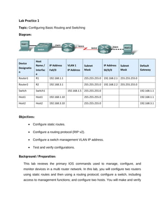
  • 1. Lab Practice 1 Topic: Configuring Basic Routing and Switching Diagram: Host Device Name / IP Address VLAN 1 Subnet IP Address Subnet Default Designatio Interfac Fa0/0 IP Address Mask S0/0/0 Mask Gateway n e Router1 R1 192.168.1.1 255.255.255.0 192.168.2.1 255.255.255.0 Router2 R2 192.168.3.1 255.255.255.0 192.168.2.2 255.255.255.0 Switch Switch1 192.168.1.5 255.255.255.0 192.168.1.1 Host1 Host1 192.168.1.10 255.255.255.0 192.168.1.1 Host2 Host2 192.168.3.10 255.255.255.0 192.168.3.1 Objectives: • Configure static routes. • Configure a routing protocol (RIP v2). • Configure a switch management VLAN IP address. • Test and verify configurations. Background / Preparation: This lab reviews the primary IOS commands used to manage, configure, and monitor devices in a multi router network. In this lab, you will configure two routers using static routes and then using a routing protocol; configure a switch, including access to management functions; and configure two hosts. You will make and verify
  • 2. configuration changes on the switch. You will also verify network configurations and connectivity. Step 1: Connect PC1 to the switch a. Connect PC1 to Fast Ethernet switch port Fa0/1. Configure PC1 to use the IP address, mask, and gateway as shown in the topology diagram. b. Establish a terminal emulation session to the switch from PC1. Step 2: Perform an initial configuration on the switch a. Configure the hostname of the switch as Switch1. Switch>enable Switch#configure terminal Switch(config)#hostname Switch1 b. Set the privileged EXEC mode password to cisco. Switch1(config)#enable password cisco c. Set the privileged EXEC mode secret password to class. Switch1(config)#enable secret class d. Configure the console and virtual terminal lines to use a password and require it at login. Switch1(config)#line console 0 Switch1(config-line)#password cisco Switch1(config-line)#login Switch1(config-line)#line vty 0 15 Switch1(config-line)#password cisco Switch1(config-line)#login Switch1(config-line)#end e. Exit from the console session and log in again. Which password was required? To access the Switch1> prompt again, the line console 0 password of cisco was required.. Which password is required to access privilege EXEC mode and why? To access privileged EXEC mode, the enable secret password of class was required because when both enable and secret passwords are configured, the IOS defaults to using the secret password. Step 3: Configure the switch management interface on VLAN 1 a. Enter the interface configuration mode for VLAN 1. Switch1(config)#interface vlan 1 b. Set the IP address, subnet mask, and default gateway for the management interface. Switch1(config-if)#ip address 192.168.1.5 255.255.255.0 Switch1(config-if)#no shutdown
  • 3. Switch1(config-if)#exit Switch1(config)#ip default-gateway 192.168.1.1 c. Why does interface VLAN1 require an IP address in this LAN? To access the switch for management purposes through virtual terminals, such as Telnet. d. What is the purpose of the default gateway? To access other networks. Step 4: Verify configuration of the switch a. Verify that the IP address of the management interface on the switch VLAN 1 and the IP address of PC1 are on the same local network. Use the show running-config command to check the IP address configuration of the switch. b. Save the configuration. Step 5: Perform basic configuration of router R1 a. Connect switch port Fa0/3 to interface Fa0/0 of router R1. b. Establish a terminal emulation session to router R1 from PC1. c. Enter privileged EXEC mode, and then global configuration mode. Router#configure terminal Enter configuration commands, one per line. End with CNTL/Z. Router(config)# d. Configure the router name as R1. Router(config)#hostname R1 e. Disable DNS lookup. R1(config)#no ip domain-lookup Why would DNS lookup be disabled in a lab environment? To keep the router from attempting to resolve domain names that are actually typographical errors. f. Configure the EXEC mode password. R1(config)#enable secret class Why is it not necessary to use the enable password password command? When both are configured, the router defaults to the enable secret password. g. Configure a message-of-the-day banner using the banner motd command. NOTE: When you use the banner motd command, you must issue a delimited character, a character to let the router know is the beginning (or ending) part of the message. Examples of
  • 4. delimiting characters include +, @, %, or $. Once you enter the beginning delimited character, you press Enter and type the lines you want to appear when someone accesses a network device. Press Enter after each line. When finished, type the same delimiting character. R1(config)#banner motd + ************************************************** Authorized Users Only! ************************************************** + R1(config)# Where does this banner display? When a user connects to the router, the MOTD banner appears before the login prompt. h. Configure the console and virtual terminal lines to use a password and require it at login. R1(config)#line console 0 R1(config-line)#password cisco R1(config-line)#login R1(config-line)#line vty 0 4 R1(config-line)#password cisco R1(config-line)#login R1(config-line)#end Step 6: Configure interfaces and static routing on router R1 a. Configure the FastEthernet 0/0 interface with the IP address 192.168.1.1/24. R1(config)#interface fastethernet 0/0 R1(config-if)#ip address 192.168.1.1 255.255.255.0 R1(config-if)#no shutdown b. Configure the Serial 0/0/0 interface with the IP address 192.168.2.1/24. Set the clock rate to 64000. R1(config-if)#interface serial 0/0/0 R1(config-if)#ip address 192.168.2.1 255.255.255.0 R1(config-if)#clock rate 64000
  • 5. R1(config-if)#no shutdown c. Return to global configuration mode. d. Create a static route to enable R1 to reach the network attached to the R2 Fa0/0 interface. Use the next hop interface on R2 as the path to this network. R1(config)#ip route 192.168.3.0 255.255.255.0 192.168.2.2 Why is this static route the only one required? Because the other networks are directly connected to R1. e. Return to privileged EXEC mode. f. Save the configuration. g. Shut down R1. Step 7: Connect PC2 to router R2 a. Connect PC2 to the FastEthernet interface 0/0 of router R2 and assign the IP address, subnet mask, and default gateway according to the lab IP address table. What kind of cable is required to connect a host directly to a router Ethernet port? Crossover cable. b. Establish a terminal emulation session with router R2 from PC2. Step 8: Perform basic configuration of router R2 a. Repeat Step 5, a through h, making the hostname R2. b. Configure the Serial 0/0/0 interface with the IP address 192.168.2.2/24. R2(config)#interface serial 0/0/0 R2(config-if)#ip address 192.168.2.2 255.255.255.0 R2(config-if)#no shutdown c. Configure the FastEthernet 0/0 interface with the IP address 192.168.3.1/24. R2(config-if)#interface fastethernet 0/0 R2(config-if)#ip address 192.168.3.1 255.255.255.0 R2(config-if)#no shutdown d. Create a static route to enable R2 to reach the network attached to the R1 Fa0/0 interface. Use the next hop interface on R1 as the path to this network. R2(config)#ip route 192.168.1.0 255.255.255.0 192.168.2.1 e. Return to privileged EXEC mode. f. Save the configuration.
  • 6. g. Shut down R2. Step 9: Connect the internetwork a. Connect R1 and R2 using a serial cable between their configured serial interfaces. b. Verify that the serial DCE cable is connected to R1 and that the serial DTE cable is connected to R2. c. Start up both routers, and log in. Step 10: Verify and test the configurations a. To verify that PC1 and Switch1 are correctly configured, ping the switch IP address from PC1. b. To verify that Switch1 and R1 are correctly configured, ping the router Fa0/0 interface (default gateway) IP address from the Switch1 CLI. c. To verify that PC2 and R2 are correctly configured, ping the router Fa0/0 interface from PC2. Were the pings successful? Should be yes. If the ping is not successful, verify the connections and configurations again. Check to ensure that all cables are correct and that connections are seated. Check the host, switch, and router configurations. d. Verify that the routing tables have routes to all configured networks by using the show ip route command. What does the “S” indicate? That route was created manually as a static route. e. Verify the router interface configurations using the show ip interface brief command. What should the output indicate for correctly configured, active interfaces? Status up, protocol up What should the output indicate for any interface that has not been configured? Status administratively down, protocol down f. View devices from R1’s terminal session using the show cdp neighbors command. If an additional switch is added between PC2 and R2, would that switch appear in this command output? No. Why or why not? CDP only displays directly-connected Cisco devices. Step 11: Remove Static Route and configure a routing protocol on router R1 a. Remove the static route to 192.168.3.0. R1(config)#no ip route 192.168.3.0 255.255.255.0 192.168.2.2 b. Enable RIP v2 routing and advertise the participating networks. R1(config)#router rip
  • 7. R1(config-router)#version 2 R1(config-router)#network 192.168.1.0 R1(config-router)#network 192.168.2.0 c. Return to privileged EXEC mode. d. Save the configuration. Step 12: Remove Static Route and configure a routing protocol on router R2 a. Remove the static route to 192.168.1.0. R2(config)#no ip route 192.168.1.0 255.255.255.0 192.168.2.1 b. Enable RIP v2 routing and advertise the participating networks. R2(config)#router rip R2(config-router)#version 2 R2(config-router)#network 192.168.2.0 R2(config-router)#network 192.168.3.0 c. Return to privileged EXEC mode. d. Save the configuration. Step 13: Verify and test the configurations a. To verify that PC1 and Switch1 are correctly configured, ping the switch IP address from PC1. b. To verify that Switch1 and R1 are correctly configured, ping the router Fa0/0 interface (default gateway) IP address from the Switch1 CLI. c. To verify that PC2 and R2 are correctly configured, ping the router Fa0/0 interface from PC2. Were the pings successful? Should be yes. If the ping is not successful, verify the connections and configurations again. Check to ensure that all cables are correct and that connections are seated. Check the host, switch, and router configurations. d. Verify that the routing tables have routes to all configured networks by using the show ip route command. R2’s routing table should display:
  • 8. What does the “R” indicate? This is a route learned through RIP. On R1, which route would be displayed with an “R”? Network 192.168.3.0 e. Verify the router interface configurations using the show ip interface brief command. f. View devices from R1’s terminal session using the show cdp neighbors command. Step 14: Use the switch management interface a. Open a command prompt on PC1, and enter the telnet command followed by the IP address assigned to management interface VLAN 1. b. Enter the vty password configured in Step 2 to gain access to the switch. c. At the switch prompt, issue the show version command. Switch1>show version d. What is the Cisco IOS version of this switch? Answers will vary. e. Determine which MAC addresses the switch has learned by using the show mac- address-table command at the privileged EXEC mode prompt. Switch1#show mac-address-table How can you determine the MAC address belonging to PC1? Page down to see the MAC address associated with port Fa0/1 At a PC1 command prompt, type ipconfig/all. Does PC1’s MAC address match one in the switch table? Yes. f. To allow the switch port FastEthernet 0/1 to accept only one device, configure port security as follows: Switch1(config)#interface fastethernet fa0/1 Switch1(config-if)#switchport mode access Switch1(config-if)#switchport port-security Switch1(config-if)#switchport port-security mac-address sticky Switch1(config-if)#end
  • 9. g. Check the port security settings. Switch1#show port-security Secure Port MaxSecureAddr CurrentAddr SecurityViolation Security Action (Count) (Count) (Count) --------------------------------------------------------------------------- Fa0/1 1 1 0 Shutdown --------------------------------------------------------------------------- If a host other than PC1 attempts to connect to Fa0/1, what will happen? The connection will be shut down. It is sometimes necessary to set the speed and duplex of a port to ensure that it operates in a particular mode. You can set the speed and duplex with the duplex and speed commands while in interface configuration mode. To force FastEthernet port 5 to operate at half duplex and 10 Mbps, issue the following commands: Switch>enable Switch#configure terminal Switch(config-if)#interface fastethernet 0/5 Switch(config-if)#speed 10 Switch(config-if)#duplex half Switch(config-if)#end Switch# h. Issue the show interfaces command. What is the duplex and speed setting for Fa0/5 now? Half-duplex, and 10 mbps. i. Enter exit at the switch command prompt to terminate the Telnet session. Step 15: Reflection a. Describe a situation in which you would use virtual terminal access to manage a switch, as you did in Step 11. Answers will vary, but could include: when the switch is located in another place, when direct Ethernet connection is not possible. b. Which symbol is used to show a successful ping in the Cisco IOS software? The exclamation point. c. Which commands used in this lab would provide the best documentation for this network? Answers will vary, but should include: Router: show ip route, show cdp neighbors, show ip int brief. Switch: show run, show start, show interfaces. d. This lab gave you an opportunity to review and display your knowledge of configuration commands. If you were asked to state three rules for “best practices” in device configuration, what would they be? Answers will vary, but could include: Type carefully Use shortcuts and arrows Always check the mode
  • 10. Save frequently e. Erase and reload all devices.