SlideShare a Scribd company logo
1 of 4
Download to read offline
construction
103www.efymag.com Electronics For You | May 2012
GSM-Based Borewell
Water-Level Monitor
Gurunath Reddy farmers to walk all the way to their
fields at night just to switch the pump
motor ‘off.’ Besides, he may never get
to know the problem.
This problem can be solved by
using this GSM-based system that
will automatically give the user a
call on his mobile
phone when the
water level in the
borewell drops
below or rises to
the threshold lev-
el for pumping.
The user can also
remotely switch
on or switch off
the pump motor
by sending an SMS from his mobile
phone. The system is simple, reliable,
portable and affordable.
Circuit description
Fig. 1 shows the block diagram of
the GSM-based borewell water-level
monitoring system. Fig. 2 shows the
complete circuit. It comprises the
power supply section, water-level sen-
sor circuit, microcontroller, MAX232
driver, relay driver and GSM modem.
The GSM board has a valid SIM card
with sufficient recharge amount to
make outgoing calls.
The circuit is powered by regulated
5V DC. The 220V, 50Hz AC mains is
stepped down by transformer X1 to
I
f the water level in a borewell
drops below the threshold level
for pumping, its pump motor may
get air-locked or even burn out due
to dry running. It is inconvenient for
Fig. 1: Block diagram of gsm-based borewell water-level monitoring system
Fig. 2: Circuit of gsm-based borewell water-level monitoring system
sunil kumar
& Sani theo
construction
104 May 2012 | Electronics For You www.efymag.com
deliver a secondary output of 12V, 250
mA. The transformer output is recti-
fied by bridge rectifier br1, filtered by
capacitor C1 and regulated by IC 7805
(IC3). Capacitor C2 bypasses ripples
from the regulated supply. LED1 acts
as the power-‘on’ indicator. Resistor R1
limits the current through LED1.
The AT89C51 microcontroller is
connected to the water-level sensor
circuit, relay driver and MAX232. The
microcontroller is programmed to take
necessary actions. The mobile number
used in the GSM modem is included in
the code before burning the code into
the microcontroller.
The water-level sensor circuit
comprises transistor T1 (BC548) as
sensor driver and water sensors A and
B dipped into the borewell along with
the pipe. Sensor A is dipped to the
threshold point for pumping and sen-
sor B is dipped below the pipe to the
bottom of the borewell.
When water in the borewell fills to
the threshold level, it is sensed by sen-
sor A and you get a call on your mobile
phone. Now you can turn the motor
‘on’ by sending the SMS “motor11 on”
from your mobile phone to the SIM
number in the GSM modem. You can
also turn the motor ‘off’ by sending the
SMS “motor11 off”.
Sensor A is connected to the base
of transistor T1 (BC548). When there
is a high voltage at the base, T1 con-
ducts and a low voltage is available
at its collector. This low signal is fed
to pin 12 (port pin p3.2) of the MCU.
Similarly, for a low voltage input at
the base, T1 stops conducting and a
high voltage signal is available at its
collector. So pin 12 of the MCU gets
a high signal input. The high or low
voltage signal at pin 12 is monitored
and processed by the program in the
MCU, and decision to turn the motor
‘off’ taken when the water level dips
below sensor A.
Pin 3 (port pin p1.2) of the MCU
is the output pin. It is connected to
relay-driver transistor T2 (BC548) and
LED2. T2 drives relay RL1, which, in
turn, activates the motor. LED2 glows
to indicate the motor-‘on’ status.
When water level in the borewell
dips below sensor A, the conduct-
ing path between sensors A and B
breaks. Hence a signal is received
by the microcontroller. The micro-
controller turns the running motor
‘off’ and makes a call to the user’s
cell phone through a GSM modem
Fig. 3: GSM modem
Table I
Motor, Mobile and LED Status for Different Water Levels
Borewell	 Water level	 Motor	 Mobile	LED2	 Remarks
Full	 Above point A	 On	 Call from modem	 On	 SMS operation to turn on/off
					 the motor
Empty	 Below point A	 Off	 Call from modem	 Off	 SMS operation not allowed
Table II
Key Features of SIM300 Series
Features 	 Implementation
Power supply 	 Single supply voltage of 3.4V-4.5V
Power saving 	 Typical power consumption in SLEEP mode: 2.5 mA
Frequency bands 	  SIM300 tri-band (EGSM 900, DCS 1800, PCS 1900). The band can be
set by AT COMMAND, and default band is EGSM 900 and DCS 1800
	  Compliant to GSM Phase 2/2+
SMS 	  MT, MO, CB, text and PDU mode
	  SMS storage: SIM card
	  Supports transmission of SMS alternatively over CSD or GPRS. User can
choose the preferred mode
SIM interface 	 Supported SIM card: 1.8V, 3V
External antenna 	 Connected via a 50-ohm antenna connector or antenna pad
Two serial interfaces 	  Serial port 1: Seven lines on the serial port interface
	  Serial port 1 can be used for CSD FAX, GPRS and sending AT command
of controlling module
	  Serial port 1 can use multiplexing function, but you cannot use serial
port 2 at the same time
	  Autobauding supports baud rate of 1200 to 115,200 bps
	  Serial port 2: Two lines on serial port interface, /TXD and /RXD
	  Serial port 2 used only for transmitting AT command
construction
105www.efymag.com Electronics For You | May 2012
to indicate that the water level is too
low to pump the water and the motor
has been switched off. In this way,
the motor is protected from airlocks
and burnouts due to dry running.
The status of motor, water level and
LED2 are shown in Table I. The GSM
modem used in this project is SIM300
V7.03 (refer Fig. 3). Its key features are
listed in Table II.
GSM modem SIM300 V7.03
The GSM module is a specialised type
of modem which accepts a SIM card
and operates on a subscriber’s mobile
number over a network, just like a cel-
lular phone. Basically, it is a cellphone
without display. Modem SIM300 is a
triband GSM/GPRS engine that works
on EGSM 900MHz, DCS 1800MHz and
PCS 1900MHz frequencies.
GSM modem is RS232-logic-level
compatible, i.e., it takes -3V to -15V as
logic ‘high’ and +3V to +15V as logic
‘low’. MAX 232 is used to convert TTL
into RS232 logic level and vice versa.
Hence MAX232 is a voltage-level
converter used between the microcon-
troller and the GSM board.
The signal at pin 11 of the micro-
controller is sent to the GSM modem
through pin 11 of MAX232. This signal
is received at Pin 2 (RX) of the GSM
Parts List
Semiconductors:
IC1 	 -	AT89C51 microcontroller
IC2	 -	MAX232 driver
IC3	 -	7805, 5V regulator
BR1 	 -	1A bridge rectifier
T1, T2	 -	BC548 npn transistor
LED1, LED2 	 -	5mm light-emitting diode
D1	 -	1N4007 rectifier diode
Resistors (all ¼-watt, ±5 per cent carbon):
R1	 -	1-kilo-ohm
R2, R6	 -	470-ohm
R3, R4 	 -	10-kilo-ohm
R5	 -	100-kilo-ohm
Capacitors:
C1	 -	1000µF, 25V electrolytic
C2, C4-C7 	 -	0.1µF ceramic
C3	 -	10µF, 16V electrolytic
C8, C9	 -	22pF ceramic
Miscellaneous:
X1	 -	220V AC primary to 12V,
		 250mA secondary
		 transformer
RL1	 -	12V, 1C/O relay
S1	 -	Tactile switch
XTAL
	 -	11.0592MHz crystal
GSM modem 	 -	SIM300 V7.03 modem
	 -	Two water-level steel sensor
		 rods
Table III
List of Commands
Command 	 Description
AT	 Check whether the serial interface
and GSM modem are working
ATE0	 Turn echo ‘off’ when there is less
traffic on serial line
AT+CNMI	 Display the new incoming SMS
AT+CPMS	 Select SMS memory
AT+CMGF	 SMS string format—how they are
compressed
AT+CMGR	 Read the new message from a
given memory location
AT+CMGS 	 Send message to a given recipient
AT+CMGD 	 Delete message
modem. The GSM modem transmits
the signal from Pin 3 (TX) to the mi-
crocontroller through MAX232, which
is received at pin 10 of IC1.
Software program
The software program is written in
‘C’ language and compiled using Keil
software. The AT commands listed in
Table III are used in the code to receive
the mobile signal. The hex code of the
program is burnt into the MCU using
Flash Magic software.
Construction and testing
An actual-size, single-side PCB layout
of the GSM-based borewell water-level
monitoring system is shown in Fig. 4
and its component layout in Fig. 5.
Fig. 4: An actual-size, single-side PCB for the GSM-based borewell water-level monitoring system
Fig. 5: Component layout for the PCB
construction
106 May 2012 | Electronics For You www.efymag.com
Fig. 6: Author’s prototype
For testing the circuit, proceed
as follows:
1. After assembling all the com-
ponents on the PCB, connect TX and
RX pins of the GSM modem to pins 13
and 14 of MAX232, respectively. Insert
a valid SIM in the card holder of the
GSM modem.
2. Connect ground pin of the GSM
modem to the ground rail of the cir-
cuit.
3. Use two single-strand (hook-up)
wires as sensor A and sensor B. (In the
actual application, use of steel rods as
sensors is recommended.) Hang the
sensors into a bucket or mug such that
sensor A is above sensor B.
4. Pour water into the bucket until
the water level reaches sensor A.
5. Now switch on the circuit.
You should get a call on your mobile
phone. This indicates that you can turn
the motor ‘on.’
6. Send SMS “motor11 on” from
any mobile phone to the SIM in the
modem to turn the motor ‘on’. You
can also turn the motor ‘off’ by send-
ing “motor11 off” message from any
mobile phone.
7. Now remove water from the
bucket until the water level in the
bucket dips below sensor A. The mo-
tor should automatically switch off
and you should receive a call from
the modem simultaneously alerting
you that the borewell (bucket in this
case) is empty and the motor has been
switched off.
After testing the above steps, you
can install the system in the borewell
by inserting sensors A and B into the
pipe with sensor B placed at the bot-
tom of the borewell as shown in the
circuit. Your borewell monitoring sys-
tem is now ready for use. The author’s
prototype is shown in Fig. 6.
EFY note. The source code of this
article is available on www.efymag.
com. 
The author is a student of BE in electronics and
telecommunications at SIT, Tumkur

More Related Content

What's hot

Pulse Modulation ppt
Pulse Modulation pptPulse Modulation ppt
Pulse Modulation pptsanjeev2419
 
Dot convention in coupled circuits
Dot convention in coupled circuitsDot convention in coupled circuits
Dot convention in coupled circuitsmrunalinithanaraj
 
Gain and Directivity Enhancement of Rectangular Microstrip Patch Antenna usin...
Gain and Directivity Enhancement of Rectangular Microstrip Patch Antenna usin...Gain and Directivity Enhancement of Rectangular Microstrip Patch Antenna usin...
Gain and Directivity Enhancement of Rectangular Microstrip Patch Antenna usin...Associate Professor in VSB Coimbatore
 
Switch mode power supply
Switch mode power supplySwitch mode power supply
Switch mode power supplyAnish Das
 
final year project report
final year project reportfinal year project report
final year project reportAnuj Kumar
 
Rec101 unit ii (part 1) bjt characteristics
Rec101 unit ii (part 1) bjt characteristicsRec101 unit ii (part 1) bjt characteristics
Rec101 unit ii (part 1) bjt characteristicsDr Naim R Kidwai
 
Strowger Switching System
Strowger Switching SystemStrowger Switching System
Strowger Switching SystemGourab Ghosh
 
DPSK(Differential Phase Shift Keying) transmitter and receiver
DPSK(Differential Phase Shift Keying) transmitter and receiverDPSK(Differential Phase Shift Keying) transmitter and receiver
DPSK(Differential Phase Shift Keying) transmitter and receiverSumukh Athrey
 
Life detection system
Life detection systemLife detection system
Life detection systemsneha manhas
 
Internship doc 33 11 kv substation
Internship doc 33 11 kv substation  Internship doc 33 11 kv substation
Internship doc 33 11 kv substation Madeen Kumar
 
Rectifier Ammeter.pptx
Rectifier Ammeter.pptxRectifier Ammeter.pptx
Rectifier Ammeter.pptxShahbazQamar2
 
Dc to Dc Converter (chopper)
Dc to Dc Converter (chopper)Dc to Dc Converter (chopper)
Dc to Dc Converter (chopper)dharmesh nakum
 
IEEE Electrical Engineering projects for Bangalore Students for Academic year...
IEEE Electrical Engineering projects for Bangalore Students for Academic year...IEEE Electrical Engineering projects for Bangalore Students for Academic year...
IEEE Electrical Engineering projects for Bangalore Students for Academic year...Igslabs Malleswaram
 
powergrid presentation
powergrid presentationpowergrid presentation
powergrid presentationAkriti Gupta
 
Mesh analysis and Nodal Analysis
Mesh analysis and Nodal AnalysisMesh analysis and Nodal Analysis
Mesh analysis and Nodal AnalysisKomal Kotak
 
Current commutated chopper
Current commutated chopperCurrent commutated chopper
Current commutated chopperJyoti Singh
 
3 phase half wave controlled converter with r Load
3 phase half wave controlled converter with r Load3 phase half wave controlled converter with r Load
3 phase half wave controlled converter with r Loadmechatronics jf
 

What's hot (20)

Pulse Modulation ppt
Pulse Modulation pptPulse Modulation ppt
Pulse Modulation ppt
 
Dot convention in coupled circuits
Dot convention in coupled circuitsDot convention in coupled circuits
Dot convention in coupled circuits
 
Gain and Directivity Enhancement of Rectangular Microstrip Patch Antenna usin...
Gain and Directivity Enhancement of Rectangular Microstrip Patch Antenna usin...Gain and Directivity Enhancement of Rectangular Microstrip Patch Antenna usin...
Gain and Directivity Enhancement of Rectangular Microstrip Patch Antenna usin...
 
Switch mode power supply
Switch mode power supplySwitch mode power supply
Switch mode power supply
 
final year project report
final year project reportfinal year project report
final year project report
 
Rec101 unit ii (part 1) bjt characteristics
Rec101 unit ii (part 1) bjt characteristicsRec101 unit ii (part 1) bjt characteristics
Rec101 unit ii (part 1) bjt characteristics
 
Strowger Switching System
Strowger Switching SystemStrowger Switching System
Strowger Switching System
 
DPSK(Differential Phase Shift Keying) transmitter and receiver
DPSK(Differential Phase Shift Keying) transmitter and receiverDPSK(Differential Phase Shift Keying) transmitter and receiver
DPSK(Differential Phase Shift Keying) transmitter and receiver
 
Unit 3 Part 1
Unit 3 Part 1Unit 3 Part 1
Unit 3 Part 1
 
CUK CONVERTER.pdf
CUK CONVERTER.pdfCUK CONVERTER.pdf
CUK CONVERTER.pdf
 
Life detection system
Life detection systemLife detection system
Life detection system
 
Internship doc 33 11 kv substation
Internship doc 33 11 kv substation  Internship doc 33 11 kv substation
Internship doc 33 11 kv substation
 
Rectifier Ammeter.pptx
Rectifier Ammeter.pptxRectifier Ammeter.pptx
Rectifier Ammeter.pptx
 
Dc to Dc Converter (chopper)
Dc to Dc Converter (chopper)Dc to Dc Converter (chopper)
Dc to Dc Converter (chopper)
 
IEEE Electrical Engineering projects for Bangalore Students for Academic year...
IEEE Electrical Engineering projects for Bangalore Students for Academic year...IEEE Electrical Engineering projects for Bangalore Students for Academic year...
IEEE Electrical Engineering projects for Bangalore Students for Academic year...
 
Cellphone Charger
Cellphone ChargerCellphone Charger
Cellphone Charger
 
powergrid presentation
powergrid presentationpowergrid presentation
powergrid presentation
 
Mesh analysis and Nodal Analysis
Mesh analysis and Nodal AnalysisMesh analysis and Nodal Analysis
Mesh analysis and Nodal Analysis
 
Current commutated chopper
Current commutated chopperCurrent commutated chopper
Current commutated chopper
 
3 phase half wave controlled converter with r Load
3 phase half wave controlled converter with r Load3 phase half wave controlled converter with r Load
3 phase half wave controlled converter with r Load
 

Viewers also liked

automatic water level controlling using gsm system
automatic water level controlling using gsm systemautomatic water level controlling using gsm system
automatic water level controlling using gsm systempavan kumar
 
water level monitor using gsm
water level monitor using gsmwater level monitor using gsm
water level monitor using gsmAditya Kumar
 
REMOTE GSM BASED MOBILE STARTER FOR MOTOR / PUMP
REMOTE GSM BASED MOBILE STARTER FOR MOTOR / PUMPREMOTE GSM BASED MOBILE STARTER FOR MOTOR / PUMP
REMOTE GSM BASED MOBILE STARTER FOR MOTOR / PUMPKHYATEE ELECTRONICS PVT.LTD
 
Monitoring & Controlling of Devices using GSM
Monitoring & Controlling of Devices using GSMMonitoring & Controlling of Devices using GSM
Monitoring & Controlling of Devices using GSMpriyanka kini
 
GSM BASED DEVICES CONTROL SYSTEM PROJECT REPORT
GSM BASED DEVICES CONTROL SYSTEM PROJECT REPORTGSM BASED DEVICES CONTROL SYSTEM PROJECT REPORT
GSM BASED DEVICES CONTROL SYSTEM PROJECT REPORTAvinash Kannojia
 
Ppt on water level indicator
Ppt on water level indicatorPpt on water level indicator
Ppt on water level indicatorpalwinder virk
 
GSM Based Motor Controller
GSM Based Motor ControllerGSM Based Motor Controller
GSM Based Motor Controllergopalsystems
 
Water level indicator
Water level indicatorWater level indicator
Water level indicatorJyotsna Rani
 
Gsm based-automatic-motor-control-and-protection-system(1)
Gsm based-automatic-motor-control-and-protection-system(1)Gsm based-automatic-motor-control-and-protection-system(1)
Gsm based-automatic-motor-control-and-protection-system(1)aayushi vijh
 
Gsm anti theft system
Gsm anti theft systemGsm anti theft system
Gsm anti theft systemAshu0711
 
Speed Control of DC motor using AT89C52 IC
Speed Control of DC motor using AT89C52 ICSpeed Control of DC motor using AT89C52 IC
Speed Control of DC motor using AT89C52 ICDisha Modi
 
GSM Based Versatile Robotic Vehicle Using PIC Microcontroller Report.
GSM Based Versatile Robotic Vehicle Using PIC Microcontroller Report.GSM Based Versatile Robotic Vehicle Using PIC Microcontroller Report.
GSM Based Versatile Robotic Vehicle Using PIC Microcontroller Report.Abee Sharma
 
LED WATER LEVEL INDICATOR WITH ALARM
LED WATER LEVEL INDICATOR WITH ALARM LED WATER LEVEL INDICATOR WITH ALARM
LED WATER LEVEL INDICATOR WITH ALARM Aditya Sharma
 
Water level indicator by bhushan kumbhalkar
Water level indicator by  bhushan kumbhalkarWater level indicator by  bhushan kumbhalkar
Water level indicator by bhushan kumbhalkarBhushan Kumbhalkar
 
Groundwater Investigation Techniques-Geophysical Methods
Groundwater Investigation Techniques-Geophysical MethodsGroundwater Investigation Techniques-Geophysical Methods
Groundwater Investigation Techniques-Geophysical MethodsGowri Prabhu
 
water level indicator alarm
water level indicator alarmwater level indicator alarm
water level indicator alarmAnish Anand
 

Viewers also liked (20)

automatic water level controlling using gsm system
automatic water level controlling using gsm systemautomatic water level controlling using gsm system
automatic water level controlling using gsm system
 
water level monitor using gsm
water level monitor using gsmwater level monitor using gsm
water level monitor using gsm
 
REMOTE GSM BASED MOBILE STARTER FOR MOTOR / PUMP
REMOTE GSM BASED MOBILE STARTER FOR MOTOR / PUMPREMOTE GSM BASED MOBILE STARTER FOR MOTOR / PUMP
REMOTE GSM BASED MOBILE STARTER FOR MOTOR / PUMP
 
Monitoring & Controlling of Devices using GSM
Monitoring & Controlling of Devices using GSMMonitoring & Controlling of Devices using GSM
Monitoring & Controlling of Devices using GSM
 
GSM BASED DEVICES CONTROL SYSTEM PROJECT REPORT
GSM BASED DEVICES CONTROL SYSTEM PROJECT REPORTGSM BASED DEVICES CONTROL SYSTEM PROJECT REPORT
GSM BASED DEVICES CONTROL SYSTEM PROJECT REPORT
 
Ppt on water level indicator
Ppt on water level indicatorPpt on water level indicator
Ppt on water level indicator
 
Water level sensors repot
Water level sensors repotWater level sensors repot
Water level sensors repot
 
GSM Based Motor Controller
GSM Based Motor ControllerGSM Based Motor Controller
GSM Based Motor Controller
 
Water level indicator
Water level indicatorWater level indicator
Water level indicator
 
Gsm based-automatic-motor-control-and-protection-system(1)
Gsm based-automatic-motor-control-and-protection-system(1)Gsm based-automatic-motor-control-and-protection-system(1)
Gsm based-automatic-motor-control-and-protection-system(1)
 
Water level indicator
Water level indicatorWater level indicator
Water level indicator
 
Gsm anti theft system
Gsm anti theft systemGsm anti theft system
Gsm anti theft system
 
Speed Control of DC motor using AT89C52 IC
Speed Control of DC motor using AT89C52 ICSpeed Control of DC motor using AT89C52 IC
Speed Control of DC motor using AT89C52 IC
 
GSM Based Versatile Robotic Vehicle Using PIC Microcontroller Report.
GSM Based Versatile Robotic Vehicle Using PIC Microcontroller Report.GSM Based Versatile Robotic Vehicle Using PIC Microcontroller Report.
GSM Based Versatile Robotic Vehicle Using PIC Microcontroller Report.
 
LED WATER LEVEL INDICATOR WITH ALARM
LED WATER LEVEL INDICATOR WITH ALARM LED WATER LEVEL INDICATOR WITH ALARM
LED WATER LEVEL INDICATOR WITH ALARM
 
Block Diagram For Control Systems.
Block Diagram For Control Systems.Block Diagram For Control Systems.
Block Diagram For Control Systems.
 
Embedded Systems Projects Ideas
Embedded Systems Projects IdeasEmbedded Systems Projects Ideas
Embedded Systems Projects Ideas
 
Water level indicator by bhushan kumbhalkar
Water level indicator by  bhushan kumbhalkarWater level indicator by  bhushan kumbhalkar
Water level indicator by bhushan kumbhalkar
 
Groundwater Investigation Techniques-Geophysical Methods
Groundwater Investigation Techniques-Geophysical MethodsGroundwater Investigation Techniques-Geophysical Methods
Groundwater Investigation Techniques-Geophysical Methods
 
water level indicator alarm
water level indicator alarmwater level indicator alarm
water level indicator alarm
 

Similar to Gsm based borewell water level monitor

KAGITHALA YASASWINI
KAGITHALA YASASWINIKAGITHALA YASASWINI
KAGITHALA YASASWINIMAHESH294
 
Electricity theft control
Electricity theft controlElectricity theft control
Electricity theft controlAffable Mee
 
Electricity theft control
Electricity theft controlElectricity theft control
Electricity theft controlAffable Mee
 
P 6168--microcontroller based-lpg_gas_detector_using_gsm_module
P 6168--microcontroller based-lpg_gas_detector_using_gsm_moduleP 6168--microcontroller based-lpg_gas_detector_using_gsm_module
P 6168--microcontroller based-lpg_gas_detector_using_gsm_moduleChitrachedu Dada Kalandar
 
prepaid energy meter using smartcard
prepaid energy meter using smartcardprepaid energy meter using smartcard
prepaid energy meter using smartcardchintu9666
 
Prepaid energy meter with gsm interface
Prepaid energy meter with gsm interfacePrepaid energy meter with gsm interface
Prepaid energy meter with gsm interfaceEdgefxkits & Solutions
 
automatic plant irrigation using aurdino and gsm technology
automatic plant irrigation using aurdino and gsm technologyautomatic plant irrigation using aurdino and gsm technology
automatic plant irrigation using aurdino and gsm technologythamil arasan
 
Gps vehicle theft identification and tracking and control
Gps vehicle theft identification and tracking and controlGps vehicle theft identification and tracking and control
Gps vehicle theft identification and tracking and controlYashwanth Yash
 
GSM Based Fault Monitoring System (Project)
GSM Based Fault Monitoring System (Project)GSM Based Fault Monitoring System (Project)
GSM Based Fault Monitoring System (Project)Aishwary Verma
 
Home automation and securty using wireless networks
Home automation and securty using wireless networksHome automation and securty using wireless networks
Home automation and securty using wireless networksArun Kumar
 
Auto dial-er Home security
Auto dial-er Home securityAuto dial-er Home security
Auto dial-er Home securityvaibhav jindal
 
TRANSFORMER HEALTH MONITORING SYSTEM
TRANSFORMER HEALTH MONITORING SYSTEMTRANSFORMER HEALTH MONITORING SYSTEM
TRANSFORMER HEALTH MONITORING SYSTEMIRJET Journal
 
Fingerprint Based Security System using GSM Module
Fingerprint Based Security System using GSM ModuleFingerprint Based Security System using GSM Module
Fingerprint Based Security System using GSM ModuleIJERA Editor
 
gsm based Notice board
gsm based Notice boardgsm based Notice board
gsm based Notice boardASHIRVAD KUMAR
 
Iisrt aprajitha malini(21 25)
Iisrt aprajitha malini(21 25)Iisrt aprajitha malini(21 25)
Iisrt aprajitha malini(21 25)IISRT
 
sms based speed change of motor or fan
sms based speed change of motor or fansms based speed change of motor or fan
sms based speed change of motor or fanRahul Gupta
 
Automated load shedding using microcontroller
Automated load shedding using microcontrollerAutomated load shedding using microcontroller
Automated load shedding using microcontrollerRajVerma175
 
IRJET - Monitoring and Protection of Distribution Transformer using GSM Module
IRJET - Monitoring and Protection of Distribution Transformer using GSM ModuleIRJET - Monitoring and Protection of Distribution Transformer using GSM Module
IRJET - Monitoring and Protection of Distribution Transformer using GSM ModuleIRJET Journal
 
IRJET- Monitoring and Protection of Distribution Transformer using GSM Module
IRJET- Monitoring and Protection of Distribution Transformer using GSM ModuleIRJET- Monitoring and Protection of Distribution Transformer using GSM Module
IRJET- Monitoring and Protection of Distribution Transformer using GSM ModuleIRJET Journal
 

Similar to Gsm based borewell water level monitor (20)

KAGITHALA YASASWINI
KAGITHALA YASASWINIKAGITHALA YASASWINI
KAGITHALA YASASWINI
 
Electricity theft control
Electricity theft controlElectricity theft control
Electricity theft control
 
Electricity theft control
Electricity theft controlElectricity theft control
Electricity theft control
 
Major Project Report.pdf
Major Project Report.pdfMajor Project Report.pdf
Major Project Report.pdf
 
P 6168--microcontroller based-lpg_gas_detector_using_gsm_module
P 6168--microcontroller based-lpg_gas_detector_using_gsm_moduleP 6168--microcontroller based-lpg_gas_detector_using_gsm_module
P 6168--microcontroller based-lpg_gas_detector_using_gsm_module
 
prepaid energy meter using smartcard
prepaid energy meter using smartcardprepaid energy meter using smartcard
prepaid energy meter using smartcard
 
Prepaid energy meter with gsm interface
Prepaid energy meter with gsm interfacePrepaid energy meter with gsm interface
Prepaid energy meter with gsm interface
 
automatic plant irrigation using aurdino and gsm technology
automatic plant irrigation using aurdino and gsm technologyautomatic plant irrigation using aurdino and gsm technology
automatic plant irrigation using aurdino and gsm technology
 
Gps vehicle theft identification and tracking and control
Gps vehicle theft identification and tracking and controlGps vehicle theft identification and tracking and control
Gps vehicle theft identification and tracking and control
 
GSM Based Fault Monitoring System (Project)
GSM Based Fault Monitoring System (Project)GSM Based Fault Monitoring System (Project)
GSM Based Fault Monitoring System (Project)
 
Home automation and securty using wireless networks
Home automation and securty using wireless networksHome automation and securty using wireless networks
Home automation and securty using wireless networks
 
Auto dial-er Home security
Auto dial-er Home securityAuto dial-er Home security
Auto dial-er Home security
 
TRANSFORMER HEALTH MONITORING SYSTEM
TRANSFORMER HEALTH MONITORING SYSTEMTRANSFORMER HEALTH MONITORING SYSTEM
TRANSFORMER HEALTH MONITORING SYSTEM
 
Fingerprint Based Security System using GSM Module
Fingerprint Based Security System using GSM ModuleFingerprint Based Security System using GSM Module
Fingerprint Based Security System using GSM Module
 
gsm based Notice board
gsm based Notice boardgsm based Notice board
gsm based Notice board
 
Iisrt aprajitha malini(21 25)
Iisrt aprajitha malini(21 25)Iisrt aprajitha malini(21 25)
Iisrt aprajitha malini(21 25)
 
sms based speed change of motor or fan
sms based speed change of motor or fansms based speed change of motor or fan
sms based speed change of motor or fan
 
Automated load shedding using microcontroller
Automated load shedding using microcontrollerAutomated load shedding using microcontroller
Automated load shedding using microcontroller
 
IRJET - Monitoring and Protection of Distribution Transformer using GSM Module
IRJET - Monitoring and Protection of Distribution Transformer using GSM ModuleIRJET - Monitoring and Protection of Distribution Transformer using GSM Module
IRJET - Monitoring and Protection of Distribution Transformer using GSM Module
 
IRJET- Monitoring and Protection of Distribution Transformer using GSM Module
IRJET- Monitoring and Protection of Distribution Transformer using GSM ModuleIRJET- Monitoring and Protection of Distribution Transformer using GSM Module
IRJET- Monitoring and Protection of Distribution Transformer using GSM Module
 

Recently uploaded

TỔNG ÔN TẬP THI VÀO LỚP 10 MÔN TIẾNG ANH NĂM HỌC 2023 - 2024 CÓ ĐÁP ÁN (NGỮ Â...
TỔNG ÔN TẬP THI VÀO LỚP 10 MÔN TIẾNG ANH NĂM HỌC 2023 - 2024 CÓ ĐÁP ÁN (NGỮ Â...TỔNG ÔN TẬP THI VÀO LỚP 10 MÔN TIẾNG ANH NĂM HỌC 2023 - 2024 CÓ ĐÁP ÁN (NGỮ Â...
TỔNG ÔN TẬP THI VÀO LỚP 10 MÔN TIẾNG ANH NĂM HỌC 2023 - 2024 CÓ ĐÁP ÁN (NGỮ Â...Nguyen Thanh Tu Collection
 
Dyslexia AI Workshop for Slideshare.pptx
Dyslexia AI Workshop for Slideshare.pptxDyslexia AI Workshop for Slideshare.pptx
Dyslexia AI Workshop for Slideshare.pptxcallscotland1987
 
Spellings Wk 3 English CAPS CARES Please Practise
Spellings Wk 3 English CAPS CARES Please PractiseSpellings Wk 3 English CAPS CARES Please Practise
Spellings Wk 3 English CAPS CARES Please PractiseAnaAcapella
 
1029-Danh muc Sach Giao Khoa khoi 6.pdf
1029-Danh muc Sach Giao Khoa khoi  6.pdf1029-Danh muc Sach Giao Khoa khoi  6.pdf
1029-Danh muc Sach Giao Khoa khoi 6.pdfQucHHunhnh
 
FSB Advising Checklist - Orientation 2024
FSB Advising Checklist - Orientation 2024FSB Advising Checklist - Orientation 2024
FSB Advising Checklist - Orientation 2024Elizabeth Walsh
 
Single or Multiple melodic lines structure
Single or Multiple melodic lines structureSingle or Multiple melodic lines structure
Single or Multiple melodic lines structuredhanjurrannsibayan2
 
SOC 101 Demonstration of Learning Presentation
SOC 101 Demonstration of Learning PresentationSOC 101 Demonstration of Learning Presentation
SOC 101 Demonstration of Learning Presentationcamerronhm
 
Making communications land - Are they received and understood as intended? we...
Making communications land - Are they received and understood as intended? we...Making communications land - Are they received and understood as intended? we...
Making communications land - Are they received and understood as intended? we...Association for Project Management
 
How to Give a Domain for a Field in Odoo 17
How to Give a Domain for a Field in Odoo 17How to Give a Domain for a Field in Odoo 17
How to Give a Domain for a Field in Odoo 17Celine George
 
On National Teacher Day, meet the 2024-25 Kenan Fellows
On National Teacher Day, meet the 2024-25 Kenan FellowsOn National Teacher Day, meet the 2024-25 Kenan Fellows
On National Teacher Day, meet the 2024-25 Kenan FellowsMebane Rash
 
Holdier Curriculum Vitae (April 2024).pdf
Holdier Curriculum Vitae (April 2024).pdfHoldier Curriculum Vitae (April 2024).pdf
Holdier Curriculum Vitae (April 2024).pdfagholdier
 
Understanding Accommodations and Modifications
Understanding  Accommodations and ModificationsUnderstanding  Accommodations and Modifications
Understanding Accommodations and ModificationsMJDuyan
 
Accessible Digital Futures project (20/03/2024)
Accessible Digital Futures project (20/03/2024)Accessible Digital Futures project (20/03/2024)
Accessible Digital Futures project (20/03/2024)Jisc
 
2024-NATIONAL-LEARNING-CAMP-AND-OTHER.pptx
2024-NATIONAL-LEARNING-CAMP-AND-OTHER.pptx2024-NATIONAL-LEARNING-CAMP-AND-OTHER.pptx
2024-NATIONAL-LEARNING-CAMP-AND-OTHER.pptxMaritesTamaniVerdade
 
Jual Obat Aborsi Hongkong ( Asli No.1 ) 085657271886 Obat Penggugur Kandungan...
Jual Obat Aborsi Hongkong ( Asli No.1 ) 085657271886 Obat Penggugur Kandungan...Jual Obat Aborsi Hongkong ( Asli No.1 ) 085657271886 Obat Penggugur Kandungan...
Jual Obat Aborsi Hongkong ( Asli No.1 ) 085657271886 Obat Penggugur Kandungan...ZurliaSoop
 
ICT Role in 21st Century Education & its Challenges.pptx
ICT Role in 21st Century Education & its Challenges.pptxICT Role in 21st Century Education & its Challenges.pptx
ICT Role in 21st Century Education & its Challenges.pptxAreebaZafar22
 
Unit-IV; Professional Sales Representative (PSR).pptx
Unit-IV; Professional Sales Representative (PSR).pptxUnit-IV; Professional Sales Representative (PSR).pptx
Unit-IV; Professional Sales Representative (PSR).pptxVishalSingh1417
 
Towards a code of practice for AI in AT.pptx
Towards a code of practice for AI in AT.pptxTowards a code of practice for AI in AT.pptx
Towards a code of practice for AI in AT.pptxJisc
 
Python Notes for mca i year students osmania university.docx
Python Notes for mca i year students osmania university.docxPython Notes for mca i year students osmania university.docx
Python Notes for mca i year students osmania university.docxRamakrishna Reddy Bijjam
 

Recently uploaded (20)

TỔNG ÔN TẬP THI VÀO LỚP 10 MÔN TIẾNG ANH NĂM HỌC 2023 - 2024 CÓ ĐÁP ÁN (NGỮ Â...
TỔNG ÔN TẬP THI VÀO LỚP 10 MÔN TIẾNG ANH NĂM HỌC 2023 - 2024 CÓ ĐÁP ÁN (NGỮ Â...TỔNG ÔN TẬP THI VÀO LỚP 10 MÔN TIẾNG ANH NĂM HỌC 2023 - 2024 CÓ ĐÁP ÁN (NGỮ Â...
TỔNG ÔN TẬP THI VÀO LỚP 10 MÔN TIẾNG ANH NĂM HỌC 2023 - 2024 CÓ ĐÁP ÁN (NGỮ Â...
 
Dyslexia AI Workshop for Slideshare.pptx
Dyslexia AI Workshop for Slideshare.pptxDyslexia AI Workshop for Slideshare.pptx
Dyslexia AI Workshop for Slideshare.pptx
 
Spellings Wk 3 English CAPS CARES Please Practise
Spellings Wk 3 English CAPS CARES Please PractiseSpellings Wk 3 English CAPS CARES Please Practise
Spellings Wk 3 English CAPS CARES Please Practise
 
1029-Danh muc Sach Giao Khoa khoi 6.pdf
1029-Danh muc Sach Giao Khoa khoi  6.pdf1029-Danh muc Sach Giao Khoa khoi  6.pdf
1029-Danh muc Sach Giao Khoa khoi 6.pdf
 
FSB Advising Checklist - Orientation 2024
FSB Advising Checklist - Orientation 2024FSB Advising Checklist - Orientation 2024
FSB Advising Checklist - Orientation 2024
 
Single or Multiple melodic lines structure
Single or Multiple melodic lines structureSingle or Multiple melodic lines structure
Single or Multiple melodic lines structure
 
SOC 101 Demonstration of Learning Presentation
SOC 101 Demonstration of Learning PresentationSOC 101 Demonstration of Learning Presentation
SOC 101 Demonstration of Learning Presentation
 
Making communications land - Are they received and understood as intended? we...
Making communications land - Are they received and understood as intended? we...Making communications land - Are they received and understood as intended? we...
Making communications land - Are they received and understood as intended? we...
 
How to Give a Domain for a Field in Odoo 17
How to Give a Domain for a Field in Odoo 17How to Give a Domain for a Field in Odoo 17
How to Give a Domain for a Field in Odoo 17
 
On National Teacher Day, meet the 2024-25 Kenan Fellows
On National Teacher Day, meet the 2024-25 Kenan FellowsOn National Teacher Day, meet the 2024-25 Kenan Fellows
On National Teacher Day, meet the 2024-25 Kenan Fellows
 
Holdier Curriculum Vitae (April 2024).pdf
Holdier Curriculum Vitae (April 2024).pdfHoldier Curriculum Vitae (April 2024).pdf
Holdier Curriculum Vitae (April 2024).pdf
 
Understanding Accommodations and Modifications
Understanding  Accommodations and ModificationsUnderstanding  Accommodations and Modifications
Understanding Accommodations and Modifications
 
Accessible Digital Futures project (20/03/2024)
Accessible Digital Futures project (20/03/2024)Accessible Digital Futures project (20/03/2024)
Accessible Digital Futures project (20/03/2024)
 
2024-NATIONAL-LEARNING-CAMP-AND-OTHER.pptx
2024-NATIONAL-LEARNING-CAMP-AND-OTHER.pptx2024-NATIONAL-LEARNING-CAMP-AND-OTHER.pptx
2024-NATIONAL-LEARNING-CAMP-AND-OTHER.pptx
 
Jual Obat Aborsi Hongkong ( Asli No.1 ) 085657271886 Obat Penggugur Kandungan...
Jual Obat Aborsi Hongkong ( Asli No.1 ) 085657271886 Obat Penggugur Kandungan...Jual Obat Aborsi Hongkong ( Asli No.1 ) 085657271886 Obat Penggugur Kandungan...
Jual Obat Aborsi Hongkong ( Asli No.1 ) 085657271886 Obat Penggugur Kandungan...
 
Mehran University Newsletter Vol-X, Issue-I, 2024
Mehran University Newsletter Vol-X, Issue-I, 2024Mehran University Newsletter Vol-X, Issue-I, 2024
Mehran University Newsletter Vol-X, Issue-I, 2024
 
ICT Role in 21st Century Education & its Challenges.pptx
ICT Role in 21st Century Education & its Challenges.pptxICT Role in 21st Century Education & its Challenges.pptx
ICT Role in 21st Century Education & its Challenges.pptx
 
Unit-IV; Professional Sales Representative (PSR).pptx
Unit-IV; Professional Sales Representative (PSR).pptxUnit-IV; Professional Sales Representative (PSR).pptx
Unit-IV; Professional Sales Representative (PSR).pptx
 
Towards a code of practice for AI in AT.pptx
Towards a code of practice for AI in AT.pptxTowards a code of practice for AI in AT.pptx
Towards a code of practice for AI in AT.pptx
 
Python Notes for mca i year students osmania university.docx
Python Notes for mca i year students osmania university.docxPython Notes for mca i year students osmania university.docx
Python Notes for mca i year students osmania university.docx
 

Gsm based borewell water level monitor

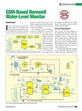
  • 1. construction 103www.efymag.com Electronics For You | May 2012 GSM-Based Borewell Water-Level Monitor Gurunath Reddy farmers to walk all the way to their fields at night just to switch the pump motor ‘off.’ Besides, he may never get to know the problem. This problem can be solved by using this GSM-based system that will automatically give the user a call on his mobile phone when the water level in the borewell drops below or rises to the threshold lev- el for pumping. The user can also remotely switch on or switch off the pump motor by sending an SMS from his mobile phone. The system is simple, reliable, portable and affordable. Circuit description Fig. 1 shows the block diagram of the GSM-based borewell water-level monitoring system. Fig. 2 shows the complete circuit. It comprises the power supply section, water-level sen- sor circuit, microcontroller, MAX232 driver, relay driver and GSM modem. The GSM board has a valid SIM card with sufficient recharge amount to make outgoing calls. The circuit is powered by regulated 5V DC. The 220V, 50Hz AC mains is stepped down by transformer X1 to I f the water level in a borewell drops below the threshold level for pumping, its pump motor may get air-locked or even burn out due to dry running. It is inconvenient for Fig. 1: Block diagram of gsm-based borewell water-level monitoring system Fig. 2: Circuit of gsm-based borewell water-level monitoring system sunil kumar & Sani theo
  • 2. construction 104 May 2012 | Electronics For You www.efymag.com deliver a secondary output of 12V, 250 mA. The transformer output is recti- fied by bridge rectifier br1, filtered by capacitor C1 and regulated by IC 7805 (IC3). Capacitor C2 bypasses ripples from the regulated supply. LED1 acts as the power-‘on’ indicator. Resistor R1 limits the current through LED1. The AT89C51 microcontroller is connected to the water-level sensor circuit, relay driver and MAX232. The microcontroller is programmed to take necessary actions. The mobile number used in the GSM modem is included in the code before burning the code into the microcontroller. The water-level sensor circuit comprises transistor T1 (BC548) as sensor driver and water sensors A and B dipped into the borewell along with the pipe. Sensor A is dipped to the threshold point for pumping and sen- sor B is dipped below the pipe to the bottom of the borewell. When water in the borewell fills to the threshold level, it is sensed by sen- sor A and you get a call on your mobile phone. Now you can turn the motor ‘on’ by sending the SMS “motor11 on” from your mobile phone to the SIM number in the GSM modem. You can also turn the motor ‘off’ by sending the SMS “motor11 off”. Sensor A is connected to the base of transistor T1 (BC548). When there is a high voltage at the base, T1 con- ducts and a low voltage is available at its collector. This low signal is fed to pin 12 (port pin p3.2) of the MCU. Similarly, for a low voltage input at the base, T1 stops conducting and a high voltage signal is available at its collector. So pin 12 of the MCU gets a high signal input. The high or low voltage signal at pin 12 is monitored and processed by the program in the MCU, and decision to turn the motor ‘off’ taken when the water level dips below sensor A. Pin 3 (port pin p1.2) of the MCU is the output pin. It is connected to relay-driver transistor T2 (BC548) and LED2. T2 drives relay RL1, which, in turn, activates the motor. LED2 glows to indicate the motor-‘on’ status. When water level in the borewell dips below sensor A, the conduct- ing path between sensors A and B breaks. Hence a signal is received by the microcontroller. The micro- controller turns the running motor ‘off’ and makes a call to the user’s cell phone through a GSM modem Fig. 3: GSM modem Table I Motor, Mobile and LED Status for Different Water Levels Borewell Water level Motor Mobile LED2 Remarks Full Above point A On Call from modem On SMS operation to turn on/off the motor Empty Below point A Off Call from modem Off SMS operation not allowed Table II Key Features of SIM300 Series Features Implementation Power supply Single supply voltage of 3.4V-4.5V Power saving Typical power consumption in SLEEP mode: 2.5 mA Frequency bands  SIM300 tri-band (EGSM 900, DCS 1800, PCS 1900). The band can be set by AT COMMAND, and default band is EGSM 900 and DCS 1800  Compliant to GSM Phase 2/2+ SMS  MT, MO, CB, text and PDU mode  SMS storage: SIM card  Supports transmission of SMS alternatively over CSD or GPRS. User can choose the preferred mode SIM interface Supported SIM card: 1.8V, 3V External antenna Connected via a 50-ohm antenna connector or antenna pad Two serial interfaces  Serial port 1: Seven lines on the serial port interface  Serial port 1 can be used for CSD FAX, GPRS and sending AT command of controlling module  Serial port 1 can use multiplexing function, but you cannot use serial port 2 at the same time  Autobauding supports baud rate of 1200 to 115,200 bps  Serial port 2: Two lines on serial port interface, /TXD and /RXD  Serial port 2 used only for transmitting AT command
  • 3. construction 105www.efymag.com Electronics For You | May 2012 to indicate that the water level is too low to pump the water and the motor has been switched off. In this way, the motor is protected from airlocks and burnouts due to dry running. The status of motor, water level and LED2 are shown in Table I. The GSM modem used in this project is SIM300 V7.03 (refer Fig. 3). Its key features are listed in Table II. GSM modem SIM300 V7.03 The GSM module is a specialised type of modem which accepts a SIM card and operates on a subscriber’s mobile number over a network, just like a cel- lular phone. Basically, it is a cellphone without display. Modem SIM300 is a triband GSM/GPRS engine that works on EGSM 900MHz, DCS 1800MHz and PCS 1900MHz frequencies. GSM modem is RS232-logic-level compatible, i.e., it takes -3V to -15V as logic ‘high’ and +3V to +15V as logic ‘low’. MAX 232 is used to convert TTL into RS232 logic level and vice versa. Hence MAX232 is a voltage-level converter used between the microcon- troller and the GSM board. The signal at pin 11 of the micro- controller is sent to the GSM modem through pin 11 of MAX232. This signal is received at Pin 2 (RX) of the GSM Parts List Semiconductors: IC1 - AT89C51 microcontroller IC2 - MAX232 driver IC3 - 7805, 5V regulator BR1 - 1A bridge rectifier T1, T2 - BC548 npn transistor LED1, LED2 - 5mm light-emitting diode D1 - 1N4007 rectifier diode Resistors (all ¼-watt, ±5 per cent carbon): R1 - 1-kilo-ohm R2, R6 - 470-ohm R3, R4 - 10-kilo-ohm R5 - 100-kilo-ohm Capacitors: C1 - 1000µF, 25V electrolytic C2, C4-C7 - 0.1µF ceramic C3 - 10µF, 16V electrolytic C8, C9 - 22pF ceramic Miscellaneous: X1 - 220V AC primary to 12V, 250mA secondary transformer RL1 - 12V, 1C/O relay S1 - Tactile switch XTAL - 11.0592MHz crystal GSM modem - SIM300 V7.03 modem - Two water-level steel sensor rods Table III List of Commands Command Description AT Check whether the serial interface and GSM modem are working ATE0 Turn echo ‘off’ when there is less traffic on serial line AT+CNMI Display the new incoming SMS AT+CPMS Select SMS memory AT+CMGF SMS string format—how they are compressed AT+CMGR Read the new message from a given memory location AT+CMGS Send message to a given recipient AT+CMGD Delete message modem. The GSM modem transmits the signal from Pin 3 (TX) to the mi- crocontroller through MAX232, which is received at pin 10 of IC1. Software program The software program is written in ‘C’ language and compiled using Keil software. The AT commands listed in Table III are used in the code to receive the mobile signal. The hex code of the program is burnt into the MCU using Flash Magic software. Construction and testing An actual-size, single-side PCB layout of the GSM-based borewell water-level monitoring system is shown in Fig. 4 and its component layout in Fig. 5. Fig. 4: An actual-size, single-side PCB for the GSM-based borewell water-level monitoring system Fig. 5: Component layout for the PCB
  • 4. construction 106 May 2012 | Electronics For You www.efymag.com Fig. 6: Author’s prototype For testing the circuit, proceed as follows: 1. After assembling all the com- ponents on the PCB, connect TX and RX pins of the GSM modem to pins 13 and 14 of MAX232, respectively. Insert a valid SIM in the card holder of the GSM modem. 2. Connect ground pin of the GSM modem to the ground rail of the cir- cuit. 3. Use two single-strand (hook-up) wires as sensor A and sensor B. (In the actual application, use of steel rods as sensors is recommended.) Hang the sensors into a bucket or mug such that sensor A is above sensor B. 4. Pour water into the bucket until the water level reaches sensor A. 5. Now switch on the circuit. You should get a call on your mobile phone. This indicates that you can turn the motor ‘on.’ 6. Send SMS “motor11 on” from any mobile phone to the SIM in the modem to turn the motor ‘on’. You can also turn the motor ‘off’ by send- ing “motor11 off” message from any mobile phone. 7. Now remove water from the bucket until the water level in the bucket dips below sensor A. The mo- tor should automatically switch off and you should receive a call from the modem simultaneously alerting you that the borewell (bucket in this case) is empty and the motor has been switched off. After testing the above steps, you can install the system in the borewell by inserting sensors A and B into the pipe with sensor B placed at the bot- tom of the borewell as shown in the circuit. Your borewell monitoring sys- tem is now ready for use. The author’s prototype is shown in Fig. 6. EFY note. The source code of this article is available on www.efymag. com.  The author is a student of BE in electronics and telecommunications at SIT, Tumkur