2. “SENTRON - Intelligent Simplicity”
In essence, modularity means: User-friendly
ease of planning, multiple use of standard
configurations - also, simple management of
changes and modification on site
The Art of Intelligent Simplicity - Sentron WL
Circuit Breakers today are no longer simple Siemens offers SENTRON WL family, which
switching and protecting devices with ON/OFF have a lot more to offer than even the so-
and trip indications. Users today are looking at called “new circuit breaker” in the market. In
circuit breakers as a device, which integrates future, it will not only be possible to carry out
switching, protection, metering and power diagnosis and maintenance procedures
management including quality of power from remotely on the Internet, but real-time
remote locations. Modern power systems are information about system malfunctions and
also characterized by the methods used to alarm signals will be made available
network circuit breakers - both with each immediately to operating staff through SMS
other and with other components. and mobile phones.
This is not a fantasy for the future; in fact it’s hard reality.
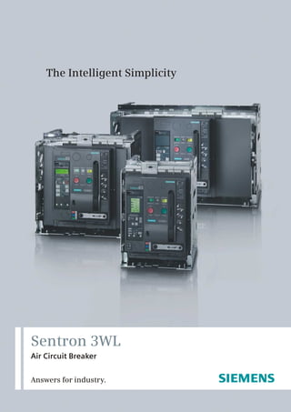
This is Sentron. A new generation of circuit breakers from 100 A to 6300 A available in three
different sizes with the following advantages.
Intelligent Modularity with Cost Savings:
• Same internal and external accessories for • Integrated CubicleBUS provides unmatched
the entire range reducing inventory cost. flexibility and cost economic solutions to all
• Compact in size. A 6300 A 3WL requires only panels - metering, protections and
800mm wide cabinet. annunciations requirements.
• Practically no deration till 55 Deg C with the • Sentron stands for complete energy
permissible service temperature upto 70 management - solution for continuous
Deg C. A 5000 A 3WL can deliver 5000 Amp energy cost supervision and optimization -
even at 70 Deg C. in short intelligent savings.
• High electrical life reduces the frequency of
replacement of contacts.
• Unique rating plug facility allows a
3200 Amp 3WL to have thermal overload
setting as low as 100A. This ensures
complete protections even when the system
is partially loaded.
2
3. Whether for rapid retrofitting, reduced
handling or optimal energy management-
anybody choosing SENTRON will profit
from clear and definite economic
Easy Planning: • Crank release lever ensures breaker removal
from the guide frame only when the contacts
• Sentron WL is available in three frame sizes yet
are seperated.
with identical door cutouts for all the frames
and at same locations on the breakers to ensure • SAFE LOCK suitable for isolation. Castell key can
standardization, symmetry and aesthetics in be removed only when the contacts are
panel design. seperated.
• Software such as 'SIMARIS' designed to support • Lockable guide frame on removal of circuit
you with evaluation, planning and calculation of breaker available as standard.
the entire system, thus saving considerable time
• Lockable withdrawable circuit breaker to protect
and energy in designing an electrical system.
against unauthorized removal provided as a
• Contact erosion indicator on the main contacts standard.
will help to plan shutdown for the contact
• High degree of IP protection class upto IP 55
maintenance.
• Mechanical reclosing lock out after overload or
• 3 breakers frame size, 3 breaking capacity, single
short-circuit release provided as standard
family and modular construction allows
feature.
optimum selection of breaker.
• The front cover cannot be removed if the circuit
breaker is in closed condition.
Maximum Safety:
• 3WL confirms to isolation requirement as per
• Distinct mechanical Ready-to-close indicator is DIN EN 60 947 - 2
provided as an inherent safety feature. This
ensures safe switching ON of ACB and eases the
diagnosis. Ready-to-close interlocking will verify System Solutions:
the following condition: • The Breaker Data Adapter(BDA) with integrated
• 3WL is switched OFF Web-server allows local parameterization,
• Storage spring is charged operation and observation of SENTRON circuit
breaker. BDA plus provides additional Ethernet
• Undervoltage released is energized
interface for remote diagnosis via LAN / WAN.
• Shunt trip not energized
• The Switch ES Power software with the same
• Closing coil not energized functionality via PROFIBUS - DP and with
• No external interlocks activated integrated object manager for integration of the
• Mechanical reclosing lockout reset SENTRON circuit breakers into SIMATIC system
3
4.
5. Standards:- The Sentron WL Circuit Breakers satisfy:
! IEC 60947 - 2, IS 13947 - 2
! DIN VDE 0660 Part 101
! UL 489 / ANSI C 37.13, UL 1066
! Climate Proof according to DIN IEC 68 Part 30 - 2
! CE Conformance
! Lloyd’s Register of shipping
User-friendly and precise:
Planning with SENTRON
5
6. 3 and 4 pole, up to 6300 A fixed - mounted and withdrawable version
Description
Microprocessor based electronic over-current release (ETU)
4
During the development of our over- current release Switch-selectable I t2or I t characteristic curve for
we have consistently striven to ensure modularity. the overload range.
The following are just some modules that are The best possible protection for the overall
simple to retrofit at any time switchgear assembly is achieved by ensuring
• Earth-fault protection module optimum setting of the release characteristic. To
• Communication modules achieve optimum selectivity of the upstream fuses
or medium-voltage protective devices, the
• Metering function inclination of the characteristic curve can be
• Displays switched over in the overload range.
• Rating plugs
This enables fast local adaptation to new network Switch-selectable parameters
conditions. At the same time, the ETU are provided In the event of a sudden change in network
with new, innovative functions like:- conditions e.g. switchover of the transformers to
generator operation or shut down of a part of the
supply network at the change of shift, SENTRON WL
Rating Plug
now supports fast adaptation of the required
The Rating Plug is a replaceable module that protective parameters to the new circumstances.
enables users to reduce the rated device current for
Two release characteristics (parameter sets) that are
optimum adaptation to the system; e.g. during
independent of one another are stored on the ETUs.
startup of a plant section. The Rating Plug should be
The transfer is executed in under 100ms and is
selected so that it roughly corresponds to the rated
initiated by an external signal.
current of the system.
Overcurrent release ETU 45B
Mechanical RESET for Option: safety lock prevents pressing of
reclosing lockout reset button after overcurrent release
Option: alphanumeric display
Scroll up Scroll down
Indicators: Indicator: fault in over current release
Over Current release
activated Thermal memory on/off
Overload alarm N-conductor protection on/off
Communication Setting value N-conductor overload
Expanded N-conductor overload
Rated current module Transfer of overload characteristic I2 t1I4t
Rotary switch for setting value, Rotary switch for delay, overload release
overload releases
Rotary switch for delay, short-circuit release
Rotary switch for setting value,
instantaneous short-circuit releases Indicator: cause of release
Sealing ring
Rotary switch for setting value, Option: earth-fault module
short-circuit protection Indicator: earth-fault alarm
Selector for earth-fault protection Rotary switch for delay earth-fault protection
Indicator: earth-fault tripped
Rotary switch for setting value, Clear push button
earth-fault protection Test socket
Rotary switch for setting value,
earth-fault alarm Query push button
Test push button
6
7. Rating Plug-in Sample configuration of an ETU 45B
size I size II size III Manual trip indicator
250A 250A
315A 315A
Text display with 15”
400A 400A inclination and rotatable
through 180”
500A 500A
630A 630A
Micro-switch for switch
700A 700A selectable overload
800A 800A characteristic curve
1000A 1000A
1250A 1250A 1250A
1600A 1600A 1600A
Rated current
2000A 2000A module rating
plug
2500A 2500A
3200A 3200A Earth-fault
protection
4000A module
(retrofittable)
5000A
6300A
example : 1000A - 3WL -> up to 1000A
rating Plug 250A ; Ir setting = 0.4 X 250 = 100A
Application: 7. Connectable and adjustable neutral conductor
Cost-effective intelligent allrounder for building and protection
all types of industrial applications- ”Cubicle BUS 8. Modular earth-fault protection, with separately
integrated”. adjustable alarm and trip function
9. Communication interface, metering function
Properties: (Plus), connection of external modules as option
1. Adjustable time-lag class for overload protection or retrofit option.
2. Short-time delayed short-circuit protection, 10. Optional high-contrast display with viewing
adjustable from 1.25... 12 x In angle adjustment
3. Instantaneous short-circuit protection adjusting 11. Overload indicator
12 In /Max/Off 12. Display of cause of trip through LED
4. Replaceable Rating Plug allows instant 13. Option for testing the release
adaptability to required plant currents, thus 14. Setting of protective functions by means of
ensuring overload protection of 100 A to 6300 A. rotary or slide switch.
5. Switch-selectable characteristic of the overload
and short-time delay short-circuit range (current
discriminate) for finer selectivity conditioning to
downstream fuses or protective devices
6. Thermal memory as restart protection in case of
tripped motor circuits
7
8. Overcurrent release ETU 76B
Mechanical RESET for Option: safety lock prevents
reclosing lockout pressing of reset button
after overcurrent release
Indicators: Graphical display
Over Current release
activated
Overload alarm Control keys for setting
COMMUNICATION the release parameters
EXPANDED
Indicator:
cause of release Indicator: fault in
Rated current module overcurrent release
Option: earth-fault Indicator:
module Earth-fault alarm
Earth-fault tripped
Fields for noting
setting values Fields for noting setting values
Test push button Clear push button
Query push button Test socket
Selection of the overcurrent releases
ETU 76B
ETU 45B
ETU 27B
ETU 25B
ETU 15B
8
9. Application:
The multitalent with graphical display for network analysis
“CubicleBUS integrated”.
Properties:
As for ETU45B plus the following:
1. Two protective parameter steps that can be stored seperately in
the release (switch-selectable through external signal).
2. Overload protection that can be switched off for use with modern
operating mechanism.
3. Adjustable lag of the delayed short-circuit protection up to
4000ms.
4. Neutral conductor protection adjustable to In = 2 In .
5. Setting of protective functions by means of control keys or
Breaker Data Adapter or through communication interface.
6. Graphical display of all parameters and event/curve
characteristics.
7. Storage of events and causes of release for specific error analysis.
8. High-contrast background - lit graphical display with sleep mode.
short-circuit protection
Freely programmable
Profibus DP/MODBUS
Instantaneous short-
Overload protection
Communication via
Metering functions
Short-time delayed
ZSI (zone-selective
Ranges / Functions
neutral conductor
circuit protection
parameter sets
Protection of
interlocking)
LCD graphic
parameters
LCD 4 lines
Earth-fault
protection
Selectable
ETU 15B
ETU 25B
ETU 27B
ETU 45B
ETU 76B
Available not available optional
9
10. Tripping characteristics
Every release type and every setting has its opening time is prolonged up to 15ms,
own characteristic. You will find just a small depending on the value of the
selection of these illustrated below. The overcurrent. To determine the total
characteristics show the respective greatest break-times of the circuit-breakers about
and smallest setting range of SENTRON WL 15ms must be added to the displayed
circuit-breakers with 1000A rated current, opening times for the arc duration.
690V rated voltage with various releases. The displayed characteristics apply for
The characteristics show the behavior of the ambient temperature at the circuit-
overcurrent release when it is activated by a breaker of -5 to +55 Deg C. The release
current already flowing before the release. can be operated at ambient
If the overcurrent release is not activated, the temperatures of -20 to +70 Deg C.
SENTRON WL circuit-breakers with I = 1000 A and ETU 45B or ETU 55B SENTRON WL circuit-breakers with I = 1000 A and ETU 45B or ETU 55B
electronic release electronic release
Inverse-time delayed overload range L Instantaneous short-circuit range l
10000 10000
t [s]
t [s]
1000 1000
100 100
10 10
1 1
.1 .1
.01 .01
100 1000 10000 100000 100 1000 10000 100000
I [A] I [A]
SENTRON WL circuit-breakers with I = 1000 A and ETU 45B or ETU 55B SENTRON WL circuit-breakers with I = 1000 A and ETU 45B or ETU 55B
electronic release electronic release
Earth-fault protection range G Short-time delayshort-circuit range S l
10000 10000
t [s]
t [s]
1000 1000
100 100
10 10
1 1
.1 .1
.01 .01
100 1000 10000 100000 100 1000 10000 100000
I [A] I [A]
2
Inverse-time delayed overload range L I t=constant
2 4
Overlapping of the Inverse-time delayed overload range L I t and I t
Inverse-time delayed overload range L I4 = constant You will find further characteristics in the
Instantaneous short-circuit range I manual or in the SIMARIS deSign planning
Earth-fault protection range G and configuring tool Or if you have any further
queries, please contact your partner.
Short-time delayed short-circuit range S
10
11. Cost Saving
Simple, rapid retrofitting
Reduced parts variance
O
No derating till 55 C
High power rating - low
space requirement
Easy to Plan
Perfectly Modular
Circuit-breakers from
100A to 6300A
Simple planning with
SIMARIS design
System Solutions
State-of-the-art
communication
Diagnosis also possible
via the Internet
Power Management
11
12. Technical Overview : SENTRON
Size I II
Type up to
3WL 11 12 3WL 11 16 3WL 12 08 3WL 12 10 3WL 12 12 3WL 12 16
3WL11 10
o
Rated current In at 55 C, at 50/60 Hz
Main conductor A up to 1000 1250 1600 800 1000 1250 1600
N-conductor (only with 4 poles) A up to 1000 1250 1600 800 1000 1250 1600
Rated operational voltage Ue at 50/60 Hz AC V up to 690 up to 690 up to 690 up to 690/ up to 690/ up to 690/ up to 690/
1000 1000 1000 1000
Rated insulation voltage Ui AC V 1000 1000 1000 1000 1000 1000 1000
Rated impulse withstand voltage Uimp
Main conducting paths kV 12 12 12 12 12 12 12
Auxiliary circuits kV 4 4 4 4 4 4 4
Control circuits kV 2.5 2.5 2.5 2.5 2.5 2.5 2.5
Isolating function according to DIN EN 60 947-2 yes yes yes yes yes yes yes
Utilization category B B
Permissible ambient temperature
o
Operation C -25/+70 -25/+70 -25/+70 -25/+70 -25/+70 -25/+70 -25/+70
o
Storage C -40/+70 -40/+70 -40/+70 -40/+70 -40/70 -40/+70 -40/+70
o
Permissible load up to 55 C A 1000 1250 1600 800 1000 1250 1600
o
for rear horizontal up to 60 C A 1000 1250 1600 800 1000 1250 1600
o
main contacts up to 70 C A 1000 1210 1490 800 1000 1250 1600
Rated short circuit making capacity lcm (peak) kA Rating Class 2) N / S S / H
upto 500V 121 / 145 176 / 220
upto 690V 88 / 105 165 / 187
upto 1000V/1150V 3) - / - - / 105
Rated service short circuit breaking capacity, Rating Class 2) N / S S / H
lcs (r.m.s) kA upto 500V 55 / 66 80 / 100
(lcs = lcu) upto 690V 42 / 50 75 / 85
upto 1000V/1150V 3) / - / 50
Rated short time withstand current, lcw. kA Rating Class 2) N / S S / H
4)
For 1 Sec at 50/60 Hz 1 Sec Rating 50 / 50 66 / 80
Power loss at In
with 3-phase symmetrical load
Fixed-mounted circuit-breaker W 100 105 150 40 45 80 85
Withdrawable circuit-breaker W 195 205 350 85 95 165 175
Operating times
Make-time ms 35 35 35 35 35 35 35
Break-time ms 38 38 38 34 34 34 34
Endurance
Mechanical (without maintenance) operating cycles 10 000 10 000 10 000 10 000 10 000 10 000 10 000
Mechanical (with maintenance) operating cycles 20 000 20 000 20 000 15 000 15 000 15 000 15 000
Electrical (without maintenance) operating cycles 10 000 10 000 10 000 75 00 75 00 75 00 75 00
Electrical (with maintenance) operating cycles 20 000 20 000 20 000 15 000 15 000 15 000 15 000
Switching frequency
690 V version 1/h 60 60 60 60 60 60 60
3)
1000V/1150V version 1/h - - - 20 20 20 20
Minimum interval ms 80 80 80 80 80 80 80
Between release by overcurrent release and next
closing of the circuit-breaker (only with autom
mechanical reset of the reclosing lockout)
0 0
Mounting position 300 300 30 30
h max
= 1 mm
and/
NS1-5150
NS1-5149
or
NSE00927
Degree of protection upto IP 55 upto IP 55
Weights Fixed-mounted circuit-breaker kg 43 43 43 56 56 56 56
3-pole Withdrawable circuit-breaker kg 45 45 45 60 60 60 60
Guide frame kg 25 25 25 31 31 31 31
4-pole Fixed-mounted circuit-breaker kg 50 50 50 67 67 67 67
Withdrawable circuit-breaker kg 54 54 54 72 72 72 72
Guide frame kg 30 30 30 37 37 37 37
SENTRON WL: An air circuitbreaker family for the complete spectrum of power distribution
whether in building infrastructure or industrial applications.
12
13. WL Air Circuit Breakers
Size II III
Type 3WL 12 20 3WL 12 25 3WL 12 32 3WL 1240 3WL 13 40 3WL 13 50 3WL 13 63
o
Rated current In at 55 C, at 50/60 Hz
1)
Main conductor A 2000 2500 3200 40003) 4000 5000 6300
N-conductor (only with 4 poles) A 2000 2500 3200 40003) 4000 5000 6300
Rated operational voltage Ue at 50/60 Hz AC V up to 690/ up to 690/ up to 690/ up to 690/ up to 690/ up to 690/ up to 690/
1000 1000 1000 1000 1000 1000 1000
Rated insulation voltage Ui AC V 1000 1000 1000 1000 1000 1000 1000
Rated impulse withstand voltage Uimp
Main conducting paths kV 12 12 12 12 12 12 12
Auxiliary circuits kV 4 4 4 4 4 4 4
Control circuits kV 2.5 2.5 2.5 2.5 2.5 2.5 2.5
Isolating function according to DIN EN 60 947-2 yes yes yes yes yes yes yes
Utilization category B B
Permissible ambient temperature
o
Operation C -25/+70 -25/+70 -25/+70 -25/+70 -25/+70 -25/+70 -25/+70
o
Storage C -40/+70 -40/+70 -40/+70 -40/+70 -40/+70 -40/+70 -40/70
Permissible load up to 55o C A 2000 2500 3200 3950 4000 5000 5920
for rear horizontal up to 60o C A 2000 2500 3070 3810 4000 5000 5810
main contacts up to 70o C A 2000 2280 2870 3600 4000 5000 5500
2)
Rated short circuit making capacity lcm (peak) kA Rating Class N / S / H H C
upto 500V 145 / 176 / 220 220 / 330(3P), 286(4P)
upto 690V 105 / 165 / 187 187 / 330(3P), 286(4P)
upto 1000V/1150V3) - / - / 105 105 / 154
2)
Rated service short circuit breaking capacity, Rating Class N / S / H H / C
lcs (r.m.s) kA upto 500V 66 / 80 / 100 100 / 150(3P), 130(4P)
(lcs = lcu) upto 690V 50 / 75 / 85 85 / 150(3P), 130(4P)
3)
upto 1000V/1150V - / - / 50 50 / 70
2)
Rated short time withstand current, lcw. KA Rating Class N / S / H H / C
For 1 Sec at 50/60 Hz 1 Sec Rating 55 / 66 / 80 100 / 100
Power loss at In
with 3-phase symmetrical load
Fixed-mounted circuit-breaker W 180 270 410 750 520 630 900
Withdrawable circuit-breaker W 320 520 710 925 810 1050 1600
Operating times
Make-time ms 35 35 35 35 35 35 35
Break-time ms 34 34 34 34 34 34 34
Endurance
Mechanical (without maintenance) operating cycles 10 000 10 000 10 000 10 000 5000 5000 5000
Mechanical (with maintenance) operating cycles 15 000 15 000 15 000 15 000 10 000 10 000 10 000
Electrical (without maintenance) operating cycles 75 00 7500 4000 4000 2000 2000 2000
Electrical (with maintenance) operating cycles 15 000 15 000 15 000 15 000 10 000 10 000 10 000
Switching frequency
690 V version 1/h 60 60 60 60 60 60 60
1000V/1150V3) version 1/h 20 20 20 20 20 20 20
Minimum interval ms 80 80 80 80 80 80 80
Between release by overcurrent release and next
closing of the circuit-breaker (only with autom
mechanical reset of the reclosing lockout)
0 0
h max
= 1 mm
Mounting position 30 30 30
0
30
0
and/
NS1-5149
NS1-5150
or
NSE00927
Degree of protection upto IP 55 upto IP 55
Weights Fixed-mounted circuit-breaker kg 56 59 64 85 82 82 90
3-pole Withdrawable circuit-breaker kg 60 63 68 121 88 88 96
Guide frame kg 31 39 45 52 60 60 70
4-pole Fixed-mounted circuit-breaker kg 67 71 77 103 99 99 108
Withdrawable circuit-breaker kg 72 76 82 146 106 106 108
Guide frame kg 37 47 54 62 84 84 119
O
* 1) At 40 C * 2) N-Normal; S-Standard; H-High 3) Class “C” - Very high breaking capacity 4) for 0.5 sec
13
14. Customised solutions: SENTRON WL
1 Draw-Out-Frame
2 Main Terminals Front, Flange, Horizontal, Vertical
3 Position-Indicating Switches
4 Leading Earth Contact
5 Shutters
6 COM 15 PROFIBUS/MODBUS COM 16 module
7 External CubicleBUS Module
8 Closing Coil, Auxiliary Releases
9 Auxiliary Plug-in System
10 Auxiliary Contact Block
11 Door Sealing Frame
12 Interlocking Kit
13 Transparent Cover, Function Block
14 Emergency Stop Pushbutton, Key Operator
15 Motorized Operator
16 Switch Operation Counter
17 Breaker Status Sensor (BSS)
18 Electronic Trip Unit (ETU)
19 Reset Coil
20 Breaker Data Adapter (BDA)
21 Four line LCD Module
22 Earth-Fault Protection Module
23 Rating Plug Module
24 Metering Module
25 Sentron WL Circuit-Breaker
14
15. with optional accessories
SENTRON WL: superior individual
products, integrated into comprehensive
power distribution system-to the extent of
providing solutions specific to particular
industrial sector and infrastructure projects
15
16. 3 and 4 pole, up to 6300A- fixed mounted and withdrawable version
Description 1) Arc chute
CIRCUIT-BREAKERS 2) Handle
3) ID label
4) Motor switch (optional) or “electrical ON”
(28) (1) (optional)
5) Type label of circuit-breaker
(2) 6) Spring charge indicator
(27)
7) “Mechanical ON” button
(26) (3) 8) Rated current data
(4) 9) Insertion pologramm
(25)
(5) 10) Operating cycle counter (optional)
11) Charging lever
(24)
(6) 12) Crank handle
(23)
13) Transport shalt for withdrawable unit
(22) (7) 14) Equipment label
(21) 15) Earth terminal
(8) 16) Position indicator
(20) (9) 17) Earth fault protection table
18) Crank handle safety lock
(19) (10) 19) “Mechanical OFF” button or “emergency OFF”
(11) mushroom push button (optional)
(18)
20) Ready-to-close indicator
(17) (12) 21) Contact position indicator
(13) 22) Trip indicator (reset button)
(16)
(14) 23) Locking device “Safe OFF” (optional)
(15) 24) Front panel
25) Terminal strip for auxiliary contacts
Description 1) Arc chute cover (optional)
GUIDE FRAME 2) Arcing openings
3) Opening for crane hooks
4) Shutter (optional)
(1) 5) Locking device (shutter) (optional)
(2)
6) Type label for guide frame
7) Disconnecting contact
(18) (3)
8) Earthing terminal O14 mm
9) Locking device travel rail
10) Locking device against moving if the cubicle
door is open (optional)
(17) (4) 11) Door interlock for guide frame (optional)
(5) 12) Guide rail
(16)
(6) 13) Ampere rating coding by factory
14) Sliding contact for circuit-breaker earthing
(7) (optional)
(15)
15) Option related coding
(14) 16) Shutter operating device (optional)
(13)
(8) 17) Position signal switch (optonal)
18) Sliding contact module for auxiliary
(12) conductor (quantity is equipment-dependent)
(9)
(11)
(10)
16
17. Description
Auxiliary release
Up to two auxiliary releases can be installed at the Operating cycle counter
same time. The following are available: A 5-digit operating cycle counter is available with the
1 shunt release or 1 undervoltage release or 2 shunt motorized operating mechanism. The display is
releases or 1 shunt release + 1 undervoltage release. incremented by “1” as soon as the stored energy
mechanism is fully charged.
Shunt release
The shunt release instantly turns off the circuit-breaker Resetting the manual trip signal
when the working voltage is applied. The shunt If the circuit breaker has been tripped, this is indicated
release “F1” is available in two versions; 5% duty ratio by the protruding red reset button on the ETU.
for over excitation and 100% duty ratio for permanent- Actuation of the reset button resets the trip solenoid
magnet excitation. This can be used as lock-out against and the trip signal. If this manual indicator is to be
startup. remotely reset, the option is available to equip the
An energy storage device for the shunt release allows reset button with a reset solenoid. With this option,
the circuit breaker to be turned off after a control the circuit breaker can be reset both manually and
voltage failure. electrically.
Undervoltage release Automatic reset of the reclosing lockout
The undervoltage release turns off the circuit breaker If the ETU is released the circuit breaker cannot be
when the working voltage falls below a specific value reclosed until the release has been either electrically or
or is not applied. The circuit breaker cannot be manually reset with the option “automatic reset of the
switched ON manually or by means of an electrical ON reclosing lockout”, the circuit breaker is ready-to-close
command if the undervoltage release is not given the immediately after a release. The reset of the manual
rated voltage. The under voltage release “Y1” is trip indicator is not contained in this option.
without time lag as standard and the customer can
switch between t1 < 80ms and t1 < 200ms. Trip signal switch
A further version is available : undervoltage release If the circuit breaker is tripped through overload, short-
with 0.2 to 3.2 s lag. circuit or earth fault, this can be indicated by the trip
signal switch. This signal switch is available as an
Signal contact for auxiliary release optional extra. If the circuit breaker is communication
One signal contact per auxiliary release is available to capable, this option is available as standard.
interrogate the switching positions of the auxiliary
release. Ready-to-close signal contact
The SENTRON WL circuit breakers are equipped with a
Closing solenoid visual ready-to-close facility as standard. The option to
Serves to electrically close the circuit breaker by means transmit this readiness to close over a signal contact is
of a local or remote electrical “ON” button. also available. If the circuit breaker is operated through
Motorized operating mechanism communication, this signal switch is fitted as standard.
For automatic charging of the stored energy
mechanism. Is switched on when the stored energy
mechanism is released and the control voltage is
available. Automatically switch off after charging.
Manual actuation of the storage can function
independently. Display message and control elements.
Interlocking set
The interlocking set is required when the operability of
the mechanical ON and OFF buttons need to be
adapted to special demands of the switchgear
operation by retrofitting various accessories (e.g.
Safety locks, access lock-outs preventing tool
operation, seals.)
Motor switch
Knob-operated switch for turning off the motorized
operating mechanism.
17
18. Locking Device
Locking device in OFF position Locking device for mechanical “OFF”
This function prevents the circuit breaker being Prevents unauthorized mechanical disconnection at
closed and fulfils the main switch-characteristics the front panel. The mechanical OFF” button can
according to EN 60 204 (VDE 0113)- line only be actuated if the key is inserted (key
disconnector. This locking only affects this circuit operation). Remote disconnection is still possible.
breaker. The blocking is only effective if the key is withdrawn.
After a circuit breaker is replaced, it is no longer
possible to prevent it being closed unless the new Locking device for charging lever
circuit breaker is also protected against The charging lever can be locked with a padlock
unauthorized closing. making it impossible to manually charge the stored
energy mechanism.
To activate the locking device, the circuit breaker
must be open. If the circuit breaker is closed, the
Locking device against resetting the trip indicator
locking device is blocked. The blocking is only
A lockable cover prevents the manual resetting of
effective if the key is withdrawn. The safety key can
the trip indicator after an overcurrent release. This
only be withdrawn in the “OFF” position.
locking device is delivered together with the option
tranparent cover for overcurrent release.
Locking device for “electrical ON”
Prevents unauthorized electrical closing at the front
panel. Mechanical and remote closing are still Sealing devices
possible. The blocking is only effective if the key is Sealing cap over “electrical ON” button
withdrawn. The “electrical ON button” is fitted with a sealing cap
as standard.
Locking device for “mechanical ON”
Prevents unauthorized mechanical closing. The Sealing cap over “mechanical ON” and “OFF”
mechanical ON button can only be actuated if the button
key is inserted (key operation). Closing through the The interlocking set includes blanking caps that can
“electrical ON” or remote closing are still possible. be sealed.
The blocking is only effective if the key is
withdrawn. Sealing device for overcurrent release
The transparent cover can be sealed. The areas of
“Safe OFF” switch independent locking device the parameter setting are covered against
against unauthorized closing. unauthorized access. Openings enable access to the
This special function for withdrawable circuit query and test button.
breakers prevents closing, independent of circuit
breaker, and fulfils the main switch-characteristics Closing lockout with open cubicle door
according to EN 60 204 (VDE 0113)- line The readiness to close is mechanically deactivated if
disconnector. Unauthorized closing is also not the cubicle door is open. The circuit breaker cannot
possible after replacement of a circuit breaker. be closed either mechanically or electrically.
To activate the locking, the circuit breaker must be Transmission of the locking signal by means of the
switched off. If the circuit breaker is switched on, Bowden wire.
the locking device is blocked. The blocking is only
effective if the key is withdrawn. The safety key can Locking device against moving if the cubicle door
only be withdrawn in the “OFF” position. is open for withdrawable circuit-breakers
The crank handle is blocked if the cubicle door is
Locking device for crank handle open and cannot be withdrawn. It is not possible to
Prevents withdrawal of the crank handle. The move withdrawable circuit breakers. The blocking is
circuit breaker is protected against moving. The only effective if the crank handle is inserted.
blocking is only effective if the key is withdrawn.
18
19. Rated current coding between circuit-breaker and guide frame
(1)
(4)
(2)
NSE01031
(3) (5)
NSE01032
(1) Guide frame, inside left; inside right are the same
(2) Coding bolt on the guide rail in the guide frame
(3) Guide rail
(4) Withdrawable circuit-breaker right side; left side are the same
(5) Coding bolt on guide frame
Interlocking of cubicle door Rated current coding between circuit breaker and
The cubicle door cannot be opened if the guide frame
- fixed-mounted circuit breaker is closed(transmission Withdrawable circuit breakers and guide frames are
of the locking signal by means of Bowden wire) or equipped with a rated current coding as standard.
- if the withdrawable circuit breaker is in connected This ensures that in a guide frame only those circuit
position. breakers can be inserted whose contact strips match
the laminated contacts of the guide frame.
Access locking through the “mechanical ON” and (see picture above)
“OFF” button Option related coding
The “mechanical ON” and “OFF” buttons are protected Withdrawable circuit breakers and guide frames can
by a cover that only permits actuation with a tool. be retrofitted with an option related coding. This
These caps are components of the interlocking set. permits the unique assignment of circuit breakers and
guide frames, taking into account different
Additional equipment for guide frames equipment. If circuit breakers and guide frames do
Shutter not have the same coding. It is not possible to insert
The cover strips of the shutter lock the laminated the circuit breaker.
contacts of the guide frame if the withdrawable circuit Circuit breakers and guide frames, taking into
breaker is withdrawn so that they fulfil the function of account different equipment. If circuit breakers and
a touch guard. guide frames do not have the same coding. It is not
The cover strips can be manually opened with the strip possible to insert the circuit breaker. There are 36
lifter. selectable coding options.
The cover strips can be fixed in different positions with
padlocks and protected from unauthorized
manipulation.
19
20. Position of the withdrawable circuit breaker in the guide frame
Position signal contact for guide frame Representation Position indicator Main circuit Auxiliary Cubicle Shutter
circuit door
Position signal contacts can be retrofitted
to the guide frame. These can be used to Maintenance CONNECT
Discon- Discon- Open Closed
(2) nected nected
position (1)
analyze the position of the circuit breaker TEST
in the guide frame. (4)
DISCONN
NSE01033 NSE01037
Mutual mechanical circuit breaker
interlocking CONNECT Discon- Discon- Closed Closed
Disconnected (3) nected nected
The module for mutual mechanical position TEST
interlocking can be implemented for two DISCONN
NSE01034
or three SENTRON WL circuit breakers and NSE01038
is simple to adapt to the respective
version. Fixed mounted and withdrawable CONNECT
Discon- Connected Closed Closed
Test position
circuit breakers are compatible and can be TEST
nected
implemented together in a single system. DISCONN
This is also possible with circuit breakers NSE01035
NSE01039
3WT.
The circuit breakers can be installed either Connected CONNECT Connected Connected Closed Open
next to one another or on top of one position
another, whereby the distance between
TEST
the circuit breakers is determined only by NSE01036
DISCONN
NSE01040
the length of the Bowden wire.
The Bowden wire are available upto a (1) Auxiliary circuit
length of 6m. Lockout signal are (2) Main circuit
forwarded over the Bowden wires with (3) Cubicle door
(4) Shutter
withdrawable circuit breakers the
interlocking is only effective in connected Mutual mechanical interlocking of circuit breaker - examples
position. The mechanical service life of Interlocking Interlocking Interlocking Interlocking of three
Bowden wires is 10000 operating cycles. of two mutual of three non- mutual of three mutual circuit breakers, two
circuit breakers circuit breakers circuit breakers of which are mutual
For the mutual mechanical interlocking of
circuit breakers also see the adjacent G
G G
S2 S1 S3
table. S1 S1 S2 S3 S1 S3
S2 S1 S2 S3 S2
Phase barriers
Plant manufacturers can make phase NSE01041 NSE01042 NSE01043 NSE01044 NSE01045
barriers out of insulation material as a
protection against internal arcs Arc chute cover
Guiding grooves are provided at the rear The arc chute cover is available as an optional features for the guide frame.
of the fixed-mounted circuit breaker or It serves to protect switchgear parts that are located directly next to the
guide frame. circuit breaker.
20
22. Technological leaders
amongst the Circuit breakers:
1 SENTRON 3VL Circuit Breaker
2 Microprocessor based release with LCD
3 Microprocessor based release
4 COM10 PROFIBUS /COM11 MODBUS module with. ZSI
5 COM20 PROFIBUS /COM21 MODBUS module with. ZSI
6 Breaker Data Adapter (BDA)
7 BDA Plus with Ethernet Interface
8 Browser-capable input & output (e.g notebook)
9 SENTRON 3WL Circuit Breaker
10 COM 15 PROFIBUS / COM 16 MODBUS Module
11 Breaker Status Sensor (BSS)
1) For a MODBUS connection the COM16 module is required
2) For a MODBUS connection the COM21 module is required
12 Microprocessor based release
13 Metering function Plus
14 ZSI (Zone-Selective Interlocking) module
15 Digital output module as relay contacts
16 Digital output module as relay contacts, configurable
17 Analog output module
18 Digital input module
19 Switch ES Power on PC
20 PLC e.g. SIMATIC S7
21 Power Management System
22 Communication capable SENTRON Power Monitoring Devices
22
24. The Cubicle BUS is the internal bus system, providing the interconnection between
all the intelligent components within the SENTRON WL (e.g. trip unit, Breaker
Status Sensor, metering function, communication module). It also permits the
simple connection of external accessory components (CubicleBUS Module, BDA
Plus) to the circuit-breaker. It is integrated as standard on all SENTRON WL circuit
breakers equipped with ETU45B and above.
External CubicleBUS Module:
By means of CubicleBUS, external accessory modules can be connected to the SENTRON WL with minimum wiring.
Available modules include: digital output modules, analog output modules, digital input modules as well as ZSI modules
for zone-selective interlocking. By using these accessories, one can save the need for similar discrete peripheral modules.
Digital output module with rotary switch
6 binary signals on the breaker status(causes of trip and warning) can be output over this module to external
signaling devices (e.g. Light, horn) or used to switch off of other specific plant parts (e.g. Frequency converter )
Digital output modules are available with or without rotart switches.
With rotary switch modules, you can choose between two signal blocks each with 6 defined assignment and an
additional response delay. All digital output modules are available either as an optocoupler output (NO contact,
150 mA) or a relay output version (change-over, up to 12A). Two module of this type may be connected to a
SENTRON WL.
Digital output module configurable
The configurable output module is available for more powerful solutions.
In this case, many events on the CubicleBUS can be directly switched to one of the six available outputs, or
three of the outputs can be assigned up to six events, i.e. Up to six events can be applied to a single physical
output with an “OR” logic operation. The configuration is executed either with BDA/BDA Plus or Switch ES Power.
As with the output modules with rotary switch, an optocoupler and a relay variant are available.
Only one module of this type can be implemented through SENTRON WL.
Analog output module
The analog output module can be used to output the following measured values of the circuit breaker to analog
display devices on the cubicle door
• Il1, IL2, IL3, IN or • COS 1,COS 2 COS 3, I% or
• UL12, UL23 UL31, ULIN or • favg, ULLavg, Ptot, COS avg
• Pl1, PL2, PL3, Stot or
Four 4-20-mA/0-10V interfaces are available for this purpose. The measured values to be output are selected
with a rotary switch. This analog output module means there is no need for additional transformers requiring
conventional installation/wiring in the main bus. Two modules of this type may be connected to a SENTRON WL.
Digital input module
The digital input module supports connection of 6 additional binary signals (24V DC) within the circuit breaker
environment to the system. This enables, for example, the status signaling of a switch disconnector or of a
cubicle door to be transmitted to PROFIBUS-DP.
With the digital input module on the Cubicle BUS, it is also possible to automatically switch the two different
protective parameter set held in the ETU 55B. And ETU- 76B releases. This allows, among other things, the
automatic changing of the parameters of a tie switch in the event of a power supply failure.
One module each of this type can be implemented for the input of the six digital signals and for the automatic
switchover of the parameters.
ZSI module
If Siemens circuit-breakers are arranged in several levels and minimal delays are desired, it is advisable to use
the ZSI module.
The circuit breakers are interconnected by these modules. In the event of a short-circuit all circuit breakers
communicate to determine and isolate the exact short-circuit location. This way only the next upstream circuit
breaker line energy flow direction will be opened.
24
25. COM15 / COM16
By means of the PROFIBUS module COM15 or MODBUS module COM16 the circuit
breakers can be connected directly to the PROFIBUS-DP or Modbus network. The
COM modules support the innovative DPV1functions. This guarantee the simplest
commissioning and diagnosis of the circuit-breaker as well as facilitates optimal
visualization of the data.
Metering Function PLUS:
The integrated metering function can be used with all trip units, equipped with
CubicleBUS interface. It is an interesting alternative to external multifunction
metering devices. Measured values include currents, voltages, powers, energy,
cos o and frequency.
The data can be shown on the display of the overcurrent releases, transmitted to
the PROFIBUS-DP through the COM15(or MODBUS through COM16) and transferred
to the outputs external CubicleBUS modules.
Measured parameters Range Accuracy
Currents I L1, IL2, IL 3, IN, Ig 30 ….. 8000 A + 1% of measurement range.
Line Voltages VL12,VL23,VL31 15 …… 130V and 130 …. 1150 V + 1% of measurement range.
Phase Volatage VL1N, VL2N, VL3N 10….75V and 75….700 V + 1% of measurement range.
Present average of line voltages V avg 10….75V and 75 …700 V + 1% of measurement range.
Apparent Power SL1,SL2,SL3 13….8000 kVA + 2% of measurement range.
Total apparent power 13…..24000kVA + 2% of measurement range.
Active power PL1, PL2,PL3 -8000 ….+ 8000 kW + 2% of apparent power ( cosØ > 0.6)
Total active power -24000 …. + 24000 kW + 2% of apparent power ( cosØ > 0.6)
Total reactive power -20000 .... + 20000 kVar + 4% of apparent power
Reactive power QL1, QL2,QL3 -6400 ….. +6400 kVar + 2% of apparent power .
Power factor Cos Ø 1, Cos Ø 2, Cos Ø 3 -0.6 …. 1 …. +0.6 + 4%
Power factor total -0.6 …. 1 …. +0.6 + 4%
Long term average of currents Il1, Il2, Il3 30 ……. 8000 A + 1% of measurement range.
Long term average of 3-phase current 30 ……. 8000 A + 1% of measurement range.
Long term average of active power in L1, L2, 13 ……. 8000 kW + 2% of apparent power ( cosØ > 0.6)
L3.
Long term average of active power 3 phase. 13 ……. 8000 kW + 2% of measurement range.
Long term average of apparent power in L1, 13 ……. 8000 kVA + 2% of measurement range.
L2, L3 and Total apparent power
Long term average of reactive power 3 - 8000 …… + 8000 kVar + 2% of apparent power .
phase.
Energy consumed 1 …… 10000 MWh + 2%
Energy delivered 1 …… 10000 MWh + 2%
Reactive energy consumed 1….. 10000 MVarh + 2%
Reactive energy delivered 1….. 10000 Mvarh + 2%
Frequency 15 ……40 Hz
40 ---- 70 Hz + 0.1 Hz
70 ---- 440 Hz
Distortion factor of current and voltage 2 …. 100% + 2% of measurement range upto 29th
harmonic
Phase unbalance of current and voltage 2 ….. 150% + 1% of displayed value.
25
26. Extended Protective functions: Parameters Range Delay
The Metering Function PLUS is used to Under voltage pickup 100 …. 1100 V 1…. 15 s
implement extended protective
Over voltage pickup 200 … 1200 V 1…..15 s
functions beyond the functionality of
the overcurrent releases. If one of these Active power in normal direction 13 …. 4000 kW 2 ….15 s
parameters exceeds or falls below its Active power in reverse direction 13 …. 4000 kW 2 ….15 s
default settings, the overcurrent release
is tripped if the set event persists longer Overfrequency pickup 40 … 70 Hz 1….15 s
than the delay time. Under frequency pickup 40 ….70 Hz 1….15 s
Phase current unbalnce pickup 5…. 50% 1….15 s
Phase voltage unbalnce pickup 5….50% 1….15 s
Phase rotation
Pickup THD current 5 …..50% 5 ….15 s
Pickup THD volatge 5 …..50% 5 ….15 s
Setpoints: Parameters Range Delay
The metering function Phase overcurrent 30 ……. 10000 A 1 ….. 255 s
PLUS provides Setpoint grond overcurrent 30 ……. 10000 A 1 ….. 255 s
Function for automatic neutral overcurrent 30 ……. 10000 A 1 ….. 255 s
monitoring of operating
phase current unbalance 5 …..50% 1 ….. 255 s
conditions and
generating warnings on current demand 30 ……10000 A 1 ….. 255 s
violation to set under voltage 15 …… 1200 V 1 ….. 255 s
threshold values. These phase voltage unbalance 5 …. 50% 1 ….. 255 s
can be communicated over voltage 15 ….. 1200 V 1 ….. 255 s
on the CubicleBUS and
over power in normal direction 13 …… 10000 kW 1 ….. 255 s
transferred via COM15.
Please Note: violation of kW reverse 13 …… 10000 kW 1 ….. 255 s
setpoint values never kW demand 13 ……. 10000 kW 1 ….. 255 s
sends tripping signal to kVA demand 13 ……. 10000 kVA 1 ….. 255 s
ETU. kVAR demand 13 ……. 10000 kVar 1 ….. 255 s
KVAR consumed 13 ……. 10000 kVAR 1 ….. 255 s
KVA 13 ……. 10000 kVA 1 ….. 255 s
over frequency 40 …. 70 Hz 1 ….. 255 s
under frequency 40 ….. 70 Hz 1 ….. 255 s
under power factors 0 …… + 0.99 1 ….. 255 s
over power factor 0 …… - 0.99 1 ….. 255 s
current THD 5 …. 50% 5 …… 255 s
voltage THD 5 …… 50% 5 ……255 s
crest factor 1….3.000 1 ….. 255 s
form factor 1….3.000 1 ….. 255 s
26
27. Waveform Memories:
The metering function Plus offers two additional If the waveform memories are programmed to
functions: "recording" (standard setting), there is continuous
recording until a previously defined event occurs.
• Two independent waveform memories. Then, the recording is stopped, and the current or
• Harmonic analysis. voltage waveforms at the time of the event can be
The two independent waveform memories can be observed through a visual display (graphical LCD,
used to analyze the current and voltages values at laptop or PC). The time window is one second; the
the time of the event. resolution is 1649 values/second.
The values that can be selected for one of the waveform memories are:
Currents I L1, I L 2 , I L 3, I L N , I g
Voltages UL1; UL2: Ul3
The waveform memories can also be started or stopped individually through the communications channels
(PROFIBUS-DP, MODBUS and Cubicle BUS).
27
28. Breaker Data Adapter BDA:
The BDA is the first circuit breaker
parameterisation device with integrated web
server for the local programming, operation
and monitoring of the SENTRON WL and
SENTRON VL. The data may be read out on
any output device with browser
capabilities(e.g. Notebook), without the
need for special software. The only system
requirement for the input / output device is a
standard browser with JAVA2 virtual
machine. Once the BDA is connected to the
circuit breaker, the browser is filled with Web
pages from BDA and the data of the circuit
breaker as shown in the following pictures.
In addition, the BDAPlus incorporates an
Ethernet interface for direct connection to
the Ethernet/Intranet/Internet.
Switch ES Power:
By means of the Switch ES Power software,
the SENTRON WL and SENTRON VL circuit
breakers can be parameterized, operated and
monitored via PROFIBUS-DP. Operational
philosophy of switches has been harmonized
with that of the BDA. An object manager
ensures complete integration into the
SIMATIC world. Thus, SENTRON becomes an
important component in Totally Integrated
Automation(TIA).
Power Management:
SENTRON circuit breakers can be easily
integrated into Power Management Systems.
This facilitates efficient diagnosis, alarm,
maintenance, cost center and load
management. SENTRON circuit breakers play
a key role in solutions provided by
Totally Integrated Power(TIP).
Breaker Data Adapter - diagnostics
Cubicle BUS SENTRON WL
Notebook
SENTRON VL
Modem
Modem
You can use modems to extend the serial connection from the notebook to the BDA to
enable the circuit breaker data to be accessed irrespective of your geographical location
28