SlideShare a Scribd company logo
1 of 7
Download to read offline
Desiccant Cooling with Solar Energy
                Gerrit Höfker1,2, Ursula Eicker2, Kevin Lomas1, Herbert Eppel1
      1
        De Montfort University Leicester, Institute of Energy and Sustainable Development
     2
        Hochschule für Technik - Fachhochschule Stuttgart, Department of Building Physics

Desiccant cooling systems combine sorptive dehumidification, heat recovery, evaporation and
heating to create a cooling process which can offer energy savings compared to conventional air
conditioning systems. Waste heat or solar energy can be used for the required regeneration of
the sorbens in the dehumidifier, leading to further energy savings. Parametric studies, particu-
larly of the dehumidifier, have been undertaken. These show that it may be possible to reduce
the regeneration air flow without a significant reduction in the dehumidification efficiency, ena-
bling desiccant cooling systems to run with high COPs. The results of the measurements were
used as input parameters for a new dynamic simulation program, which was specifically devel-
oped for the purpose of assessing the potential for desiccant cooling under different climatic
conditions.

Introduction
Cooling is important for space conditioning of most buildings in warm climates and in non-
residential buildings with high internal cooling loads in cooler climates. Along with the growth
of cooling loads in modern buildings with low thermal inertia, the peak electricity demand in-
creases during the day. This causes problems concerning the energy supply in some countries,
as the demand for air conditioning occurs simultaneously with the maximum demand of indus-
try and households. The inertia of energy plants leads to a high consumption of coal, oil, gas
and nuclear energy by energy companies to ensure the provision of electricity. To depress the
swing of energy demand during the day, solar energy for cooling purposes could make a signifi-
cant contribution to lowering the energy consumption. The solar cooling technology presented
in this paper is based on a process combining sorptive dehumidification, heat recovery, evapo-
ration and heating. The so-called desiccant cooling system takes air from outside or from the
building, dehumidifies it with a solid or liquid desiccant, cools it by heat exchange and then
evaporatively cools it to the desired state of a maximum 100% relative humidity in the inlet air
stream. The desiccant must be regenerated by heat. This can be achieved with solar energy from
solar air collectors or liquid collectors.

                                         air collector


                                bypass
                     fan


                                                                     humidifiers


                               Sorp
                                                                                   fan
                           dehumidifier                  heat recovery
Figure 1: Desiccant cooling system with solar air collectors

Figure 1 shows how solar air collectors can be integrated. Adaptation to liquid collectors is also
possible with an air/liquid heat exchanger. By using solar liquid collectors the storage possibil-
ity can increase the content of solar energy to the required auxiliary energy. The example in
Figure 2 shows the desiccant cooling process under usual design conditions for middle Europe
(ϑamb = 32°C, rh = 40%; ϑin = 26°C, rh = 55%). Figure 3 shows the process in a psychrometric
chart, where the state points are numbered to correspond to the points on the process schematic.
Ambient air is dried and heated by a dehumidifier from 1 to 2, regeneratively cooled by exhaust
air from 2 to 3, evaporatively cooled from 3 to 4 and then brought into the building. The inlet
humidifier allows control of the temperature and humidity. Exhaust air at state 5 from the inside
of the building moves in the opposite direction and is evaporatively cooled to 6 up to saturation.
At 7 the air is heated by the energy removed from the heat regenerator. From 7 to 8 solar or
other heat must increase the temperature up to the regeneration level of the desiccant to regener-
ate the dehumidifier.

                         dehumidifier            heater        heat recovery         humidifiers

               ϑ = 45.2°C        ϑ = 70.0°C            ϑ = 45.8°C         ϑ = 20.1°C          ϑ = 26.0°C
               rh = 32%          rh = 6%               rh = 22%           rh = 96%            rh = 55%
               X = 20.0 g/kg     X = 14.1 g/kg         X = 14.1 g/kg      X = 14.1 g/kg       X = 11.6 g/kg

                   9                    8                  7                   6                   5


                   1           Sorp                2                           3                   4
               ϑ = 32°C                      ϑ = 50.4°C                   ϑ = 24.6°C          ϑ = 16.0°C
               rh = 40%                      rh = 9%                      rh = 31%            rh = 93%
               X = 11.9 g/kg                 X = 6.0 g/kg                 X = 6.0 g/kg        X = 9.9 g/kg
Figure 2: Conditions of air in a desiccant cooling system. A bypass flow of 25% is considered.

                                30
                                                                             0.5               0.2                      0.05


                                25
    absolute humidity [g/kg]


                                                                             9
                                20


                                15                                               7
                                                  6                                                       8
                                                                   1                                                    0.02
                                10            4                5


                                 5                                                        2
                                                           3

                                 0
                                     0   10           20           30   40           50       60     70       80   90      100
                                                                        temperature [°C]

                               Figure 3: Process of a desiccant cooling system plotted in a psychrometric chart

Measurements
The world-wide first test plant for open cycle desiccant cooling systems with solar air collectors
has been installed at the Hochschule für Technik in Stuttgart. With the modular setup, a quick
change of components is possible. This enables parameter studies to be conducted easily. The
test plant was developed under aspects of very precise measurement conditions. With regard to
the choice of sensors, the measurement of temperatures and relative humidity do not cause
problems. However, measuring air flow in compact plants is very complicated. A totally devel-
oped symmetrical flow profile is only possible in very long ductwork. Turbulences appear at
bends and expansions of ducts and falsify the measurement results. This was the reason for us-
ing long tubes to connect the components of the desiccant cooling systems. Each component
was connected to the tubes with special concentric adapters.

The measurements of the rotating dehumidifier were of greatest interest, and hence were inves-
tigated in detail. The dehumidification achieved depends on the inlet conditions of the entering
air, on the velocities in the process and the regeneration section and the regeneration tempera-
ture and humidity. Furthermore, the rotation speed influences the performance significantly.
Fifteen rounds per hour were determined as optimal for dehumidification. A faster rotation leads
to incomplete regeneration and dehumidification. Lower rotation speeds lead to a lower dehu-
midification, as the maximum possible water content in the adsorbens is reached some time
before entering the regeneration section. In the regeneration section the water is removed before
entering the process section resulting in an unfavourable increase in the adsorbens temperature.
This causes a reduced adsorption in the process section, and the adsorbens must first be cooled
down by the inlet air until the adsorption process can restart.
For the measurements of the dehumidification, the process air flow was constant at VP = 2530
m³/h while the regeneration air flow was changed from VR = 2530 m³/h down to VR = 890 m³/h.
This corresponds to a ratio of VR/VP = 1.00 down to VR/VP = 0.35. To obtain relevant state-
ments on the performance of the dehumidification with low regeneration air flows, it was neces-
sary to improve the seals of the dehumidifier. With the non-improved seals, noticeable leakage
air flows appeared due to the pressure difference in the different flow sections and valid meas-
urement results were not achievable.

The maximum possible dehumidification depends on the thermodynamic properties of the en-
tering air streams. The process air can be maximally dehumidified down to rh = constant, which
is marked by the condition of the regeneration air. The ratio of the reached value for dehumidi-
fication to the ideal dehumidification is defined as the dehumidification efficiency. The results
of the dehumidification efficiencies ηsorp of this study are

                                   VR/VP = 0.35     ηsorp = 0.62
                                   VR/VP = 0.50     ηsorp = 0.75
                                   VR/VP = 0.75     ηsorp = 0.82
                                   VR/VP = 1.00     ηsorp = 0.87

Particularly interesting in these results is the fact that the dehumidification efficiency decreases
only by 7% while the air flow is reduced from VR/VP = 0.75, which is the usual operating mode,
to VR/VP = 0.50. An air flow ratio of VR/VP = 0.35 would decrease the dehumidification effi-
ciency by 20%. A balanced air flow with VR/VP = 1.00 results in a dehumidification efficiency
which is only 5% higher than in the usual operating mode. A reduction of the regeneration air
flow is important for saving energy, as the energy input for regeneration is linearly dependent
on the regeneration air flow.

The small reduction of the dehumidification efficiency compared to the reduction of air flow
can be explained with the faster desorption velocity compared to the adsorption velocity. This
can be justified with the assumption that capillary condensation takes place in micropores which
are placed in front of macropores while these are still filled with vapour. So the adsorption pro-
cess will be slowed down. During desorption the macropores are filled with liquid water at the
same vapour pressure and the desorption process will not be delayed. A further justification is
the fact that the heat and mass transfer coefficients only change with the square root of the air
velocity.

Simulations
For the task of this work the program ESIMA, which is an abbreviation of "Energy Simulation
in Mathematica", was developed. It is a modular simulation tool for dynamic thermal building
simulations and was evaluated with the BESTEST procedure [1]. It was developed to calculate
the performance of buildings and plants and their interaction. The simulations presented here
were made with a room analogous to BESTEST case 940, which represents a heavyweight
building. This building with a floor area of 48 m² was assumed to be occupied by 5 persons, of
whom emit 100 W of sensible heat and 30 g/h of moisture. Furthermore, an internal cooling
load of 20 W/m² was assumed during the time of occupancy between 8 a.m. and 6 p.m. A con-
stant air change of 0.2 1/h was fixed to take building leakage into account. The indoor air tem-
peratures were set to a minimum of 20°C during occupancy time and were set back to 15°C
outside the occupancy time. The maximum permissible indoor air temperatures vary according
to DIN 1946 depending on the ambient air temperature. A desiccant cooling system pro-
grammed with the algorithm provided in [2] was connected to this building. During the occu-
pancy time a fresh air demand from the desiccant cooling system of a minimum of 150 m³/h and
a maximum of 518 m³/h, which equals an air change of 4 1/h, was considered. The constant
parameters of this system were a heat recovery efficiency of 0.85 and a humidifier efficiency of
0.90. For the dehumidifier the efficiencies measured at the test plant were used. The system can
operate in different modes listed below depending on the indoor air conditions.

1. Heat recovery mode HR. Used for highly efficient heat recovery enabling the heat recovery
   and the dehumidifier to be used as an enthalpy exchanger. Enabled for ϑi < 22°C.
2. Ventilation mode V. Used only for ventilation without enabling any thermal component of
   the system. Enabled for 22°C ≤ ϑi < 23°C.
3. Adiabatic cooling mode AC. Used for cooling if dehumidification is not necessary or inlet
   temperatures are low enough, enabling the outlet humidifier and the heat recovery wheel.
   Enabled for 23°C ≤ ϑi < 24°C.
4. Desiccant cooling mode DCS. Classic operating mode enabling all components of the entire
   system. Enabled for ϑi ≥ 24°C.
5. Desiccant cooling mode DCS*. Used if indoor relative humidity is over 60%. Classic oper-
   ating mode enabling all components except the inlet humidifier. Enabled for ϑi ≥ 24°C.

The heat supply of the desiccant cooling system is only achieved with solar air collectors. This
signifies that no energy storage is available in either the desiccant cooling system or the solar
system. A thermal inertia is only provided by the mass of the building. One of the main pa-
rameters describing the performance of an entire desiccant cooling system is the coefficient of
performance, abbreviated as COP. For the calculation of the COP it is usual to use enthalpy
differences instead of temperature differences to show the influence of dehumidification. To
calculate the enthalpies required for the calculation of the COP, each condition of air along the
system must be evaluated. These conditions can only be calculated with a knowledge of the
components performance.

The described test building and the adapted desiccant cooling system with solar air collectors
were simulated for the climatic situations of Djakarta in Indonesia, Phoenix (Arizona) in the
United States, Seville in Spain and Stuttgart in Germany. The climatic data for each location
were produced with the program Meteonorm 4.0 [3].

   Table 1: Results of annual simulations for the performance of a desiccant cooling system
                   adapted to a heavyweight building in different climates.

              Mean COP Additional            DCS       Peak                 Control mode
               only for   cooling           system  cooling load           during operation
              DCS mode    demand            cooling
              DCS* mode                     energy
                 [-]    [kWh/m²a]         [kWh/m²a]   [W/m²]                      [-]
                                                                          HR            0.00
                                                                          V             0.00
 Djakarta         4.04         218.4          2.6           67.8          AC            0.00
                                                                         DCS            0.12
                                                                         DCS*           0.88
                                                                          HR            0.01
                                                                          V             0.09
  Phoenix         1.02          54.5         160.4          96.3          AC            0.07
DCS            0.70
                                                                         DCS*           0.13
                                                                          HR            0.04
                                                                          V             0.11
  Seville         1.12          34.9         121.7          89.1          AC            0.07
                                                                         DCS            0.58
                                                                         DCS*           0.20
                                                                          HR            0.36
                                                                          V             0.16
 Stuttgart        0.57          6.9           58.0          40.8          AC            0.09
                                                                         DCS            0.36
                                                                         DCS*           0.02


The simulation results show that in heavyweight buildings the use of solar energy alone without
any storage system can cover 89% of the cooling demand in Stuttgart, 78% of the cooling de-
mand in Seville, 75% of the cooling demand in Phoenix and only 1% of the cooling demand in
Djakarta. In the tropical climate of Djakarta or during humid periods in Phoenix and Seville, it
is necessary to disable the function of the inlet humidifier (control mode DCS*), resulting in an
inlet air temperature close to the room conditions. Hence the cooling capacity of the system is
very low. On the other hand, the simulations show that in humid climates the gained COPs of
the desiccant cooling systems are high and reach values greater than 1. This shows that it is
extremely useful to install desiccant cooling systems working only for sorptive dehumidifica-
tion, which is less energy-consuming than dehumidification in common air conditioning sys-
tems, where the air must be cooled to below or close to the dew point temperature. For the re-
quirements of deep dehumidification in climates with an ambient-air absolute humidity often
greater than 15 g/kg, an additional component for dehumidification is necessary. Therefore, a
second rotating dehumidifier and a second heat recovery can be used as shown in Figure 4. A
desiccant cooling system with this configuration can cover 29% of the cooling demand.
Sorp                                  Sorp


      Figure 4: Desiccant cooling system with solar air collectors for deep dehumidification


Conclusions
Using solar energy for cooling purposes is an attractive idea with good prospects for conven-
tional air conditioning systems. The replacement of compressor cooling systems by solar driven
desiccant cooling systems or a combination of both could make an important contribution to
environmental protection. The main argument for the applicability of solar energy is that cool-
ing loads and solar availability are approximately in phase. Due to the combination of solar
cooling and heating, solar collectors which are used only for heating purposes would become
more economical. Parametric studies showed that it may be possible to reduce the regeneration
air flow without a significant reduction in the dehumidification efficiency, enabling desiccant
cooling systems to run with high COPs. Results of annual simulations showed the potential for
desiccant cooling under different climatic conditions. The largest solar fractions were evaluated
for climatic conditions of Central Europe. In climates with high ambient-air absolute humidities,
additional dehumidification devices are necessary. Therefore, a sophisticated configuration of a
desiccant cooling system was presented where a second heat recovery and a second dehumidi-
fier is used.

References
[1]    Judkoff, R.; Neymark, J.: International Energy Agency building energy simulation test
       (BESTEST) and diagnostic method. National Renewable Energy Laboratory Golden
       Colorado, 1995.
[2]    Höfker, G.: Desiccant Cooling with Solar Energy. PhD thesis. De Montfort University
       Leicester, 2001. Due for completion in March 2001.
[3]    Meteonorm 4.0: Global meteorological database for solar energy and applied climatol-
       ogy. Meteotest Bern, 1999.

More Related Content

What's hot

GREEN ENGINE TECHNOLOGY BY HANUMANTHAPPA N UBDTCE
GREEN ENGINE TECHNOLOGY BY HANUMANTHAPPA N UBDTCEGREEN ENGINE TECHNOLOGY BY HANUMANTHAPPA N UBDTCE
GREEN ENGINE TECHNOLOGY BY HANUMANTHAPPA N UBDTCEHanumanth Ubdtce
 
Difference between si and ci engine
Difference between si and ci engineDifference between si and ci engine
Difference between si and ci engineRupesh Kumar
 
Air conditioning-system
Air conditioning-systemAir conditioning-system
Air conditioning-systemraheel77
 
Vapour Absorption Refrigeration System
Vapour Absorption Refrigeration SystemVapour Absorption Refrigeration System
Vapour Absorption Refrigeration SystemJaswanth Gejjala
 
Vapour absorption refrigeration systems
Vapour absorption refrigeration systemsVapour absorption refrigeration systems
Vapour absorption refrigeration systemsAkshay Mistri
 
Air Conditioning System
Air Conditioning SystemAir Conditioning System
Air Conditioning SystemSumit Ranjan
 
S3 Lec 3 (Evaporator) Note
S3 Lec 3 (Evaporator) NoteS3 Lec 3 (Evaporator) Note
S3 Lec 3 (Evaporator) Noteno suhaila
 
Feedwater heaters in thermal power plants
Feedwater heaters in thermal power plantsFeedwater heaters in thermal power plants
Feedwater heaters in thermal power plantsSHIVAJI CHOUDHURY
 
SOLAR REFRIGERATION SYSTEM
SOLAR REFRIGERATION SYSTEM SOLAR REFRIGERATION SYSTEM
SOLAR REFRIGERATION SYSTEM ANJIPULLAGURA
 
Air cooled chillers vs water cooled chillers
Air cooled chillers vs water cooled chillersAir cooled chillers vs water cooled chillers
Air cooled chillers vs water cooled chillersChiller Service
 
ENGINE LUBRICATING SYSTEM
ENGINE LUBRICATING SYSTEMENGINE LUBRICATING SYSTEM
ENGINE LUBRICATING SYSTEMBRS ENGINEERING
 
Bootstrap Refrigeration
Bootstrap RefrigerationBootstrap Refrigeration
Bootstrap Refrigerationjonnydas
 
Summer air conditioning system
Summer air conditioning systemSummer air conditioning system
Summer air conditioning systemrefrigerationgyaan
 
Compressed Air Purification Adsorption Technology
Compressed Air Purification   Adsorption TechnologyCompressed Air Purification   Adsorption Technology
Compressed Air Purification Adsorption TechnologyPaulus Hartanto
 

What's hot (20)

GREEN ENGINE TECHNOLOGY BY HANUMANTHAPPA N UBDTCE
GREEN ENGINE TECHNOLOGY BY HANUMANTHAPPA N UBDTCEGREEN ENGINE TECHNOLOGY BY HANUMANTHAPPA N UBDTCE
GREEN ENGINE TECHNOLOGY BY HANUMANTHAPPA N UBDTCE
 
Stratified-charge-engine-ppt
Stratified-charge-engine-pptStratified-charge-engine-ppt
Stratified-charge-engine-ppt
 
Difference between si and ci engine
Difference between si and ci engineDifference between si and ci engine
Difference between si and ci engine
 
Air conditioning-system
Air conditioning-systemAir conditioning-system
Air conditioning-system
 
Surge in compressor
Surge in compressorSurge in compressor
Surge in compressor
 
Vapour Absorption Refrigeration System
Vapour Absorption Refrigeration SystemVapour Absorption Refrigeration System
Vapour Absorption Refrigeration System
 
Seminar on green engine
Seminar  on green engineSeminar  on green engine
Seminar on green engine
 
Solar Refrigeration System
Solar Refrigeration SystemSolar Refrigeration System
Solar Refrigeration System
 
Vapour absorption refrigeration systems
Vapour absorption refrigeration systemsVapour absorption refrigeration systems
Vapour absorption refrigeration systems
 
Air Conditioning System
Air Conditioning SystemAir Conditioning System
Air Conditioning System
 
S3 Lec 3 (Evaporator) Note
S3 Lec 3 (Evaporator) NoteS3 Lec 3 (Evaporator) Note
S3 Lec 3 (Evaporator) Note
 
Feedwater heaters in thermal power plants
Feedwater heaters in thermal power plantsFeedwater heaters in thermal power plants
Feedwater heaters in thermal power plants
 
Chiller ppt
Chiller pptChiller ppt
Chiller ppt
 
SOLAR REFRIGERATION SYSTEM
SOLAR REFRIGERATION SYSTEM SOLAR REFRIGERATION SYSTEM
SOLAR REFRIGERATION SYSTEM
 
Air cooled chillers vs water cooled chillers
Air cooled chillers vs water cooled chillersAir cooled chillers vs water cooled chillers
Air cooled chillers vs water cooled chillers
 
ENGINE LUBRICATING SYSTEM
ENGINE LUBRICATING SYSTEMENGINE LUBRICATING SYSTEM
ENGINE LUBRICATING SYSTEM
 
Bootstrap Refrigeration
Bootstrap RefrigerationBootstrap Refrigeration
Bootstrap Refrigeration
 
Summer air conditioning system
Summer air conditioning systemSummer air conditioning system
Summer air conditioning system
 
dual fuel engine
dual fuel enginedual fuel engine
dual fuel engine
 
Compressed Air Purification Adsorption Technology
Compressed Air Purification   Adsorption TechnologyCompressed Air Purification   Adsorption Technology
Compressed Air Purification Adsorption Technology
 

Similar to Desiccant

Feasibility Analysis Of Solar Air Dehumidifier_Vishal Sharma_pg no 62-66.pdf
Feasibility Analysis Of Solar Air Dehumidifier_Vishal Sharma_pg no 62-66.pdfFeasibility Analysis Of Solar Air Dehumidifier_Vishal Sharma_pg no 62-66.pdf
Feasibility Analysis Of Solar Air Dehumidifier_Vishal Sharma_pg no 62-66.pdfRajasthan Technical University Kota
 
DOC-20231017-WA0003..pptx
DOC-20231017-WA0003..pptxDOC-20231017-WA0003..pptx
DOC-20231017-WA0003..pptxKarthik029CSK
 
Am318385
Am318385Am318385
Am318385IJMER
 
Final Year Project Presentation.pptx
Final Year Project Presentation.pptxFinal Year Project Presentation.pptx
Final Year Project Presentation.pptxFaisal115831
 
A Systemic Optimization Approach for the Design of Natural Gas Dehydration Plant
A Systemic Optimization Approach for the Design of Natural Gas Dehydration PlantA Systemic Optimization Approach for the Design of Natural Gas Dehydration Plant
A Systemic Optimization Approach for the Design of Natural Gas Dehydration PlantIJRES Journal
 
Energy Loss Minimization through Chiller Ball Cleaning Technique
Energy Loss Minimization through Chiller Ball Cleaning TechniqueEnergy Loss Minimization through Chiller Ball Cleaning Technique
Energy Loss Minimization through Chiller Ball Cleaning TechniqueJedh Quenano
 
Basics Overview of Vapour Absorption Machine.pptx
Basics Overview of Vapour Absorption Machine.pptxBasics Overview of Vapour Absorption Machine.pptx
Basics Overview of Vapour Absorption Machine.pptxAmiya Kumar Samal
 
Psychrometry and air conditioning
Psychrometry and air conditioningPsychrometry and air conditioning
Psychrometry and air conditioningnitin184shukla
 
Paper Bubble Expansion Valve ID913
Paper Bubble Expansion Valve ID913Paper Bubble Expansion Valve ID913
Paper Bubble Expansion Valve ID913Svenning Ericsson
 
Chap_14_lecture.ppt
Chap_14_lecture.pptChap_14_lecture.ppt
Chap_14_lecture.pptQiyeZheng2
 
Dc lab 5
Dc lab 5Dc lab 5
Dc lab 5ykhan60
 

Similar to Desiccant (20)

Air conditioning
Air conditioningAir conditioning
Air conditioning
 
H1304025762
H1304025762H1304025762
H1304025762
 
Dehumidifier System
Dehumidifier SystemDehumidifier System
Dehumidifier System
 
Feasibility Analysis Of Solar Air Dehumidifier_Vishal Sharma_pg no 62-66.pdf
Feasibility Analysis Of Solar Air Dehumidifier_Vishal Sharma_pg no 62-66.pdfFeasibility Analysis Of Solar Air Dehumidifier_Vishal Sharma_pg no 62-66.pdf
Feasibility Analysis Of Solar Air Dehumidifier_Vishal Sharma_pg no 62-66.pdf
 
Psychrometric
PsychrometricPsychrometric
Psychrometric
 
DOC-20231017-WA0003..pptx
DOC-20231017-WA0003..pptxDOC-20231017-WA0003..pptx
DOC-20231017-WA0003..pptx
 
Am318385
Am318385Am318385
Am318385
 
Final Year Project Presentation.pptx
Final Year Project Presentation.pptxFinal Year Project Presentation.pptx
Final Year Project Presentation.pptx
 
A Systemic Optimization Approach for the Design of Natural Gas Dehydration Plant
A Systemic Optimization Approach for the Design of Natural Gas Dehydration PlantA Systemic Optimization Approach for the Design of Natural Gas Dehydration Plant
A Systemic Optimization Approach for the Design of Natural Gas Dehydration Plant
 
Kapes project
Kapes projectKapes project
Kapes project
 
Ppt.hybrid ac
Ppt.hybrid acPpt.hybrid ac
Ppt.hybrid ac
 
Energy Loss Minimization through Chiller Ball Cleaning Technique
Energy Loss Minimization through Chiller Ball Cleaning TechniqueEnergy Loss Minimization through Chiller Ball Cleaning Technique
Energy Loss Minimization through Chiller Ball Cleaning Technique
 
Basics Overview of Vapour Absorption Machine.pptx
Basics Overview of Vapour Absorption Machine.pptxBasics Overview of Vapour Absorption Machine.pptx
Basics Overview of Vapour Absorption Machine.pptx
 
Article - 2012 PTQ Q1
Article - 2012 PTQ Q1Article - 2012 PTQ Q1
Article - 2012 PTQ Q1
 
Psychrometry and air conditioning
Psychrometry and air conditioningPsychrometry and air conditioning
Psychrometry and air conditioning
 
Paper Bubble Expansion Valve ID913
Paper Bubble Expansion Valve ID913Paper Bubble Expansion Valve ID913
Paper Bubble Expansion Valve ID913
 
Chap_14_lecture.ppt
Chap_14_lecture.pptChap_14_lecture.ppt
Chap_14_lecture.ppt
 
Dc lab 5
Dc lab 5Dc lab 5
Dc lab 5
 
PSYCHROMETRY
PSYCHROMETRYPSYCHROMETRY
PSYCHROMETRY
 
G04563844
G04563844G04563844
G04563844
 

More from ahp2011

Chapter+7,+function+of+management.pptx
Chapter+7,+function+of+management.pptxChapter+7,+function+of+management.pptx
Chapter+7,+function+of+management.pptxahp2011
 
Chapter+6,+Introduction+to+Management.pptx
Chapter+6,+Introduction+to+Management.pptxChapter+6,+Introduction+to+Management.pptx
Chapter+6,+Introduction+to+Management.pptxahp2011
 
Chapter+6,+Introduction+to+Management.pptx
Chapter+6,+Introduction+to+Management.pptxChapter+6,+Introduction+to+Management.pptx
Chapter+6,+Introduction+to+Management.pptxahp2011
 
Chapter+4,+Basic+Economics+Problems.pptx
Chapter+4,+Basic+Economics+Problems.pptxChapter+4,+Basic+Economics+Problems.pptx
Chapter+4,+Basic+Economics+Problems.pptxahp2011
 
Chapter+3,+Market+and+National+Income.pptx
Chapter+3,+Market+and+National+Income.pptxChapter+3,+Market+and+National+Income.pptx
Chapter+3,+Market+and+National+Income.pptxahp2011
 
Chapter 2 A Conceptual Framework for Industry 4.0 2.pptx
Chapter 2 A Conceptual Framework for Industry 4.0 2.pptxChapter 2 A Conceptual Framework for Industry 4.0 2.pptx
Chapter 2 A Conceptual Framework for Industry 4.0 2.pptxahp2011
 
Chapter+1,+Introduction+to+Economics.pptx
Chapter+1,+Introduction+to+Economics.pptxChapter+1,+Introduction+to+Economics.pptx
Chapter+1,+Introduction+to+Economics.pptxahp2011
 
Chapter+2,+Theory+of+Production.pptx
Chapter+2,+Theory+of+Production.pptxChapter+2,+Theory+of+Production.pptx
Chapter+2,+Theory+of+Production.pptxahp2011
 
chapter8-161127140005.pdf
chapter8-161127140005.pdfchapter8-161127140005.pdf
chapter8-161127140005.pdfahp2011
 
Energy Scenario _chapter 1 .pdf
Energy Scenario _chapter 1 .pdfEnergy Scenario _chapter 1 .pdf
Energy Scenario _chapter 1 .pdfahp2011
 
Dynamics of communication .pdf
Dynamics of communication .pdfDynamics of communication .pdf
Dynamics of communication .pdfahp2011
 
Chapter 2 A Conceptual Framework for Industry 4.0.pptx
Chapter 2 A Conceptual Framework for Industry 4.0.pptxChapter 2 A Conceptual Framework for Industry 4.0.pptx
Chapter 2 A Conceptual Framework for Industry 4.0.pptxahp2011
 
Design of experiments .pdf
Design of experiments .pdfDesign of experiments .pdf
Design of experiments .pdfahp2011
 
Gears .pdf
Gears .pdfGears .pdf
Gears .pdfahp2011
 
Gear .pdf
Gear .pdfGear .pdf
Gear .pdfahp2011
 
Clutches-pptx.pptx
Clutches-pptx.pptxClutches-pptx.pptx
Clutches-pptx.pptxahp2011
 
Transmission of Power.pptx
Transmission of Power.pptxTransmission of Power.pptx
Transmission of Power.pptxahp2011
 
Brakes.pdf
Brakes.pdfBrakes.pdf
Brakes.pdfahp2011
 

More from ahp2011 (18)

Chapter+7,+function+of+management.pptx
Chapter+7,+function+of+management.pptxChapter+7,+function+of+management.pptx
Chapter+7,+function+of+management.pptx
 
Chapter+6,+Introduction+to+Management.pptx
Chapter+6,+Introduction+to+Management.pptxChapter+6,+Introduction+to+Management.pptx
Chapter+6,+Introduction+to+Management.pptx
 
Chapter+6,+Introduction+to+Management.pptx
Chapter+6,+Introduction+to+Management.pptxChapter+6,+Introduction+to+Management.pptx
Chapter+6,+Introduction+to+Management.pptx
 
Chapter+4,+Basic+Economics+Problems.pptx
Chapter+4,+Basic+Economics+Problems.pptxChapter+4,+Basic+Economics+Problems.pptx
Chapter+4,+Basic+Economics+Problems.pptx
 
Chapter+3,+Market+and+National+Income.pptx
Chapter+3,+Market+and+National+Income.pptxChapter+3,+Market+and+National+Income.pptx
Chapter+3,+Market+and+National+Income.pptx
 
Chapter 2 A Conceptual Framework for Industry 4.0 2.pptx
Chapter 2 A Conceptual Framework for Industry 4.0 2.pptxChapter 2 A Conceptual Framework for Industry 4.0 2.pptx
Chapter 2 A Conceptual Framework for Industry 4.0 2.pptx
 
Chapter+1,+Introduction+to+Economics.pptx
Chapter+1,+Introduction+to+Economics.pptxChapter+1,+Introduction+to+Economics.pptx
Chapter+1,+Introduction+to+Economics.pptx
 
Chapter+2,+Theory+of+Production.pptx
Chapter+2,+Theory+of+Production.pptxChapter+2,+Theory+of+Production.pptx
Chapter+2,+Theory+of+Production.pptx
 
chapter8-161127140005.pdf
chapter8-161127140005.pdfchapter8-161127140005.pdf
chapter8-161127140005.pdf
 
Energy Scenario _chapter 1 .pdf
Energy Scenario _chapter 1 .pdfEnergy Scenario _chapter 1 .pdf
Energy Scenario _chapter 1 .pdf
 
Dynamics of communication .pdf
Dynamics of communication .pdfDynamics of communication .pdf
Dynamics of communication .pdf
 
Chapter 2 A Conceptual Framework for Industry 4.0.pptx
Chapter 2 A Conceptual Framework for Industry 4.0.pptxChapter 2 A Conceptual Framework for Industry 4.0.pptx
Chapter 2 A Conceptual Framework for Industry 4.0.pptx
 
Design of experiments .pdf
Design of experiments .pdfDesign of experiments .pdf
Design of experiments .pdf
 
Gears .pdf
Gears .pdfGears .pdf
Gears .pdf
 
Gear .pdf
Gear .pdfGear .pdf
Gear .pdf
 
Clutches-pptx.pptx
Clutches-pptx.pptxClutches-pptx.pptx
Clutches-pptx.pptx
 
Transmission of Power.pptx
Transmission of Power.pptxTransmission of Power.pptx
Transmission of Power.pptx
 
Brakes.pdf
Brakes.pdfBrakes.pdf
Brakes.pdf
 

Desiccant

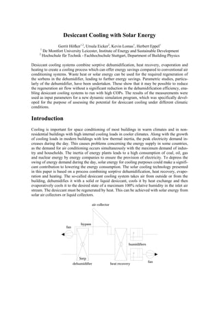
  • 1. Desiccant Cooling with Solar Energy Gerrit Höfker1,2, Ursula Eicker2, Kevin Lomas1, Herbert Eppel1 1 De Montfort University Leicester, Institute of Energy and Sustainable Development 2 Hochschule für Technik - Fachhochschule Stuttgart, Department of Building Physics Desiccant cooling systems combine sorptive dehumidification, heat recovery, evaporation and heating to create a cooling process which can offer energy savings compared to conventional air conditioning systems. Waste heat or solar energy can be used for the required regeneration of the sorbens in the dehumidifier, leading to further energy savings. Parametric studies, particu- larly of the dehumidifier, have been undertaken. These show that it may be possible to reduce the regeneration air flow without a significant reduction in the dehumidification efficiency, ena- bling desiccant cooling systems to run with high COPs. The results of the measurements were used as input parameters for a new dynamic simulation program, which was specifically devel- oped for the purpose of assessing the potential for desiccant cooling under different climatic conditions. Introduction Cooling is important for space conditioning of most buildings in warm climates and in non- residential buildings with high internal cooling loads in cooler climates. Along with the growth of cooling loads in modern buildings with low thermal inertia, the peak electricity demand in- creases during the day. This causes problems concerning the energy supply in some countries, as the demand for air conditioning occurs simultaneously with the maximum demand of indus- try and households. The inertia of energy plants leads to a high consumption of coal, oil, gas and nuclear energy by energy companies to ensure the provision of electricity. To depress the swing of energy demand during the day, solar energy for cooling purposes could make a signifi- cant contribution to lowering the energy consumption. The solar cooling technology presented in this paper is based on a process combining sorptive dehumidification, heat recovery, evapo- ration and heating. The so-called desiccant cooling system takes air from outside or from the building, dehumidifies it with a solid or liquid desiccant, cools it by heat exchange and then evaporatively cools it to the desired state of a maximum 100% relative humidity in the inlet air stream. The desiccant must be regenerated by heat. This can be achieved with solar energy from solar air collectors or liquid collectors. air collector bypass fan humidifiers Sorp fan dehumidifier heat recovery
  • 2. Figure 1: Desiccant cooling system with solar air collectors Figure 1 shows how solar air collectors can be integrated. Adaptation to liquid collectors is also possible with an air/liquid heat exchanger. By using solar liquid collectors the storage possibil- ity can increase the content of solar energy to the required auxiliary energy. The example in Figure 2 shows the desiccant cooling process under usual design conditions for middle Europe (ϑamb = 32°C, rh = 40%; ϑin = 26°C, rh = 55%). Figure 3 shows the process in a psychrometric chart, where the state points are numbered to correspond to the points on the process schematic. Ambient air is dried and heated by a dehumidifier from 1 to 2, regeneratively cooled by exhaust air from 2 to 3, evaporatively cooled from 3 to 4 and then brought into the building. The inlet humidifier allows control of the temperature and humidity. Exhaust air at state 5 from the inside of the building moves in the opposite direction and is evaporatively cooled to 6 up to saturation. At 7 the air is heated by the energy removed from the heat regenerator. From 7 to 8 solar or other heat must increase the temperature up to the regeneration level of the desiccant to regener- ate the dehumidifier. dehumidifier heater heat recovery humidifiers ϑ = 45.2°C ϑ = 70.0°C ϑ = 45.8°C ϑ = 20.1°C ϑ = 26.0°C rh = 32% rh = 6% rh = 22% rh = 96% rh = 55% X = 20.0 g/kg X = 14.1 g/kg X = 14.1 g/kg X = 14.1 g/kg X = 11.6 g/kg 9 8 7 6 5 1 Sorp 2 3 4 ϑ = 32°C ϑ = 50.4°C ϑ = 24.6°C ϑ = 16.0°C rh = 40% rh = 9% rh = 31% rh = 93% X = 11.9 g/kg X = 6.0 g/kg X = 6.0 g/kg X = 9.9 g/kg
  • 3. Figure 2: Conditions of air in a desiccant cooling system. A bypass flow of 25% is considered. 30 0.5 0.2 0.05 25 absolute humidity [g/kg] 9 20 15 7 6 8 1 0.02 10 4 5 5 2 3 0 0 10 20 30 40 50 60 70 80 90 100 temperature [°C] Figure 3: Process of a desiccant cooling system plotted in a psychrometric chart Measurements The world-wide first test plant for open cycle desiccant cooling systems with solar air collectors has been installed at the Hochschule für Technik in Stuttgart. With the modular setup, a quick change of components is possible. This enables parameter studies to be conducted easily. The test plant was developed under aspects of very precise measurement conditions. With regard to the choice of sensors, the measurement of temperatures and relative humidity do not cause problems. However, measuring air flow in compact plants is very complicated. A totally devel- oped symmetrical flow profile is only possible in very long ductwork. Turbulences appear at bends and expansions of ducts and falsify the measurement results. This was the reason for us- ing long tubes to connect the components of the desiccant cooling systems. Each component was connected to the tubes with special concentric adapters. The measurements of the rotating dehumidifier were of greatest interest, and hence were inves- tigated in detail. The dehumidification achieved depends on the inlet conditions of the entering air, on the velocities in the process and the regeneration section and the regeneration tempera- ture and humidity. Furthermore, the rotation speed influences the performance significantly. Fifteen rounds per hour were determined as optimal for dehumidification. A faster rotation leads to incomplete regeneration and dehumidification. Lower rotation speeds lead to a lower dehu- midification, as the maximum possible water content in the adsorbens is reached some time before entering the regeneration section. In the regeneration section the water is removed before entering the process section resulting in an unfavourable increase in the adsorbens temperature. This causes a reduced adsorption in the process section, and the adsorbens must first be cooled down by the inlet air until the adsorption process can restart.
  • 4. For the measurements of the dehumidification, the process air flow was constant at VP = 2530 m³/h while the regeneration air flow was changed from VR = 2530 m³/h down to VR = 890 m³/h. This corresponds to a ratio of VR/VP = 1.00 down to VR/VP = 0.35. To obtain relevant state- ments on the performance of the dehumidification with low regeneration air flows, it was neces- sary to improve the seals of the dehumidifier. With the non-improved seals, noticeable leakage air flows appeared due to the pressure difference in the different flow sections and valid meas- urement results were not achievable. The maximum possible dehumidification depends on the thermodynamic properties of the en- tering air streams. The process air can be maximally dehumidified down to rh = constant, which is marked by the condition of the regeneration air. The ratio of the reached value for dehumidi- fication to the ideal dehumidification is defined as the dehumidification efficiency. The results of the dehumidification efficiencies ηsorp of this study are VR/VP = 0.35 ηsorp = 0.62 VR/VP = 0.50 ηsorp = 0.75 VR/VP = 0.75 ηsorp = 0.82 VR/VP = 1.00 ηsorp = 0.87 Particularly interesting in these results is the fact that the dehumidification efficiency decreases only by 7% while the air flow is reduced from VR/VP = 0.75, which is the usual operating mode, to VR/VP = 0.50. An air flow ratio of VR/VP = 0.35 would decrease the dehumidification effi- ciency by 20%. A balanced air flow with VR/VP = 1.00 results in a dehumidification efficiency which is only 5% higher than in the usual operating mode. A reduction of the regeneration air flow is important for saving energy, as the energy input for regeneration is linearly dependent on the regeneration air flow. The small reduction of the dehumidification efficiency compared to the reduction of air flow can be explained with the faster desorption velocity compared to the adsorption velocity. This can be justified with the assumption that capillary condensation takes place in micropores which are placed in front of macropores while these are still filled with vapour. So the adsorption pro- cess will be slowed down. During desorption the macropores are filled with liquid water at the same vapour pressure and the desorption process will not be delayed. A further justification is the fact that the heat and mass transfer coefficients only change with the square root of the air velocity. Simulations For the task of this work the program ESIMA, which is an abbreviation of "Energy Simulation in Mathematica", was developed. It is a modular simulation tool for dynamic thermal building simulations and was evaluated with the BESTEST procedure [1]. It was developed to calculate the performance of buildings and plants and their interaction. The simulations presented here were made with a room analogous to BESTEST case 940, which represents a heavyweight building. This building with a floor area of 48 m² was assumed to be occupied by 5 persons, of whom emit 100 W of sensible heat and 30 g/h of moisture. Furthermore, an internal cooling load of 20 W/m² was assumed during the time of occupancy between 8 a.m. and 6 p.m. A con- stant air change of 0.2 1/h was fixed to take building leakage into account. The indoor air tem- peratures were set to a minimum of 20°C during occupancy time and were set back to 15°C outside the occupancy time. The maximum permissible indoor air temperatures vary according to DIN 1946 depending on the ambient air temperature. A desiccant cooling system pro-
  • 5. grammed with the algorithm provided in [2] was connected to this building. During the occu- pancy time a fresh air demand from the desiccant cooling system of a minimum of 150 m³/h and a maximum of 518 m³/h, which equals an air change of 4 1/h, was considered. The constant parameters of this system were a heat recovery efficiency of 0.85 and a humidifier efficiency of 0.90. For the dehumidifier the efficiencies measured at the test plant were used. The system can operate in different modes listed below depending on the indoor air conditions. 1. Heat recovery mode HR. Used for highly efficient heat recovery enabling the heat recovery and the dehumidifier to be used as an enthalpy exchanger. Enabled for ϑi < 22°C. 2. Ventilation mode V. Used only for ventilation without enabling any thermal component of the system. Enabled for 22°C ≤ ϑi < 23°C. 3. Adiabatic cooling mode AC. Used for cooling if dehumidification is not necessary or inlet temperatures are low enough, enabling the outlet humidifier and the heat recovery wheel. Enabled for 23°C ≤ ϑi < 24°C. 4. Desiccant cooling mode DCS. Classic operating mode enabling all components of the entire system. Enabled for ϑi ≥ 24°C. 5. Desiccant cooling mode DCS*. Used if indoor relative humidity is over 60%. Classic oper- ating mode enabling all components except the inlet humidifier. Enabled for ϑi ≥ 24°C. The heat supply of the desiccant cooling system is only achieved with solar air collectors. This signifies that no energy storage is available in either the desiccant cooling system or the solar system. A thermal inertia is only provided by the mass of the building. One of the main pa- rameters describing the performance of an entire desiccant cooling system is the coefficient of performance, abbreviated as COP. For the calculation of the COP it is usual to use enthalpy differences instead of temperature differences to show the influence of dehumidification. To calculate the enthalpies required for the calculation of the COP, each condition of air along the system must be evaluated. These conditions can only be calculated with a knowledge of the components performance. The described test building and the adapted desiccant cooling system with solar air collectors were simulated for the climatic situations of Djakarta in Indonesia, Phoenix (Arizona) in the United States, Seville in Spain and Stuttgart in Germany. The climatic data for each location were produced with the program Meteonorm 4.0 [3]. Table 1: Results of annual simulations for the performance of a desiccant cooling system adapted to a heavyweight building in different climates. Mean COP Additional DCS Peak Control mode only for cooling system cooling load during operation DCS mode demand cooling DCS* mode energy [-] [kWh/m²a] [kWh/m²a] [W/m²] [-] HR 0.00 V 0.00 Djakarta 4.04 218.4 2.6 67.8 AC 0.00 DCS 0.12 DCS* 0.88 HR 0.01 V 0.09 Phoenix 1.02 54.5 160.4 96.3 AC 0.07
  • 6. DCS 0.70 DCS* 0.13 HR 0.04 V 0.11 Seville 1.12 34.9 121.7 89.1 AC 0.07 DCS 0.58 DCS* 0.20 HR 0.36 V 0.16 Stuttgart 0.57 6.9 58.0 40.8 AC 0.09 DCS 0.36 DCS* 0.02 The simulation results show that in heavyweight buildings the use of solar energy alone without any storage system can cover 89% of the cooling demand in Stuttgart, 78% of the cooling de- mand in Seville, 75% of the cooling demand in Phoenix and only 1% of the cooling demand in Djakarta. In the tropical climate of Djakarta or during humid periods in Phoenix and Seville, it is necessary to disable the function of the inlet humidifier (control mode DCS*), resulting in an inlet air temperature close to the room conditions. Hence the cooling capacity of the system is very low. On the other hand, the simulations show that in humid climates the gained COPs of the desiccant cooling systems are high and reach values greater than 1. This shows that it is extremely useful to install desiccant cooling systems working only for sorptive dehumidifica- tion, which is less energy-consuming than dehumidification in common air conditioning sys- tems, where the air must be cooled to below or close to the dew point temperature. For the re- quirements of deep dehumidification in climates with an ambient-air absolute humidity often greater than 15 g/kg, an additional component for dehumidification is necessary. Therefore, a second rotating dehumidifier and a second heat recovery can be used as shown in Figure 4. A desiccant cooling system with this configuration can cover 29% of the cooling demand.
  • 7. Sorp Sorp Figure 4: Desiccant cooling system with solar air collectors for deep dehumidification Conclusions Using solar energy for cooling purposes is an attractive idea with good prospects for conven- tional air conditioning systems. The replacement of compressor cooling systems by solar driven desiccant cooling systems or a combination of both could make an important contribution to environmental protection. The main argument for the applicability of solar energy is that cool- ing loads and solar availability are approximately in phase. Due to the combination of solar cooling and heating, solar collectors which are used only for heating purposes would become more economical. Parametric studies showed that it may be possible to reduce the regeneration air flow without a significant reduction in the dehumidification efficiency, enabling desiccant cooling systems to run with high COPs. Results of annual simulations showed the potential for desiccant cooling under different climatic conditions. The largest solar fractions were evaluated for climatic conditions of Central Europe. In climates with high ambient-air absolute humidities, additional dehumidification devices are necessary. Therefore, a sophisticated configuration of a desiccant cooling system was presented where a second heat recovery and a second dehumidi- fier is used. References [1] Judkoff, R.; Neymark, J.: International Energy Agency building energy simulation test (BESTEST) and diagnostic method. National Renewable Energy Laboratory Golden Colorado, 1995. [2] Höfker, G.: Desiccant Cooling with Solar Energy. PhD thesis. De Montfort University Leicester, 2001. Due for completion in March 2001. [3] Meteonorm 4.0: Global meteorological database for solar energy and applied climatol- ogy. Meteotest Bern, 1999.