

Empfohlen
Weitere ähnliche Inhalte
Was ist angesagt?
Was ist angesagt? (20)
Ähnlich wie Compass surveying essentials
Ähnlich wie Compass surveying essentials (20)
Kürzlich hochgeladen
Kürzlich hochgeladen (20)
Compass surveying essentials
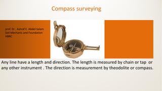
- 1. Compass surveying Any line have a length and direction. The length is measured by chain or tap or any other instrument . The direction is measurement by theodolite or compass. prof. Dr . Ashraf E. Abdel-Salam Soil Mechanic and Foundation HBRC
- 2. What Is The Compass A compass is an instrument designed for the measurement of directions with reference to the magnetic meridian. The two main types of compass • Prismatic compass • Surveyor`s compass
- 6. Parts of a Compass The basic parts of a base-plate compass are described below and illustrated in last fig. Magnetic needle. The magnetic needle typically has a red end that points to magnetic north, as long as the compass is being used properly and there is no local magnetic attraction. Housing with cardinal points and degrees. The housing includes a revolving dial that shows the cardinal points (at least north, east, south, and west) and degrees (0 – 360) The housing is rotated to line up the compass needle with the orienting arrow when taking a bearing. Orienting arrow. The north-south orienting arrow (red or black outline of an arrow) is used to align the magnetic needle when taking a bearing. It is also what is adjusted to set the compass for magnetic declination. Orienting lines. The north-south orienting lines parallel the orienting arrow and can be used to line up the compass dial with grid lines on a map. When the declination is set on a compass with an adjustment screw, the orienting lines no longer parallel the orienting arrow. Index line. Marked on the front sight of the compass base plate, the index line is where you read the indicated bearing.
- 7. Index line. Marked on the front sight of the compass base plate, the index line is where you read the indicated bearing. Direction of travel arrow. The direction of travel arrow or sighting line is used for sighting and following bearings. The arrow should be pointed in the direction of the destination or landmark. Base plate. The transparent plate (everything is attached to the baseplate) can be used as a ruler to measure map distances. The direction of travel arrow is also located on the baseplate. Some compasses will have a protractor on the baseplate that can be used to determine bearings from a map. Magnifying lens. Useful for reading tiny map symbols and features. Declination adjustment screw. Some compasses have a screw that can be turned to set compass for proper declination. Some compasses have an internal adjustment that utomatically corrects for declination. Clinometer. Some compasses have a clinometer that can be used to estimate slope. Sighting mirror. Some compasses have a flip up mirror that can improve accuracy when reading bearings. Read the bearing in the dial’s reflection where the mirror line crosses it. It can also be used for signaling.
- 8. The different between the prismatic and surveyors compass
- 9. Bearing The angle between the survey lines and the fixed line of reference with a compass True meridian The true or geographical meridian passing through a point is the line in which the earth`s surface is intersected by a plane through the north and south poles and the given point Magnetic meridian Magnetic meridian at a place is the direction indicated by a freely floating and properly balanced magnetic needle , and the horizontal angle between the two directions is called the magnetic Direction , and the angle between a survey line and the magnetic meridian is called the magnetic Bearing.
- 10. Adjusting a Compass for Magnetic Declination The compass needle always points toward magnetic north; however, topographic maps are drawn in reference to true north (North Pole). The difference between magnetic north and true north is called the angle of magnetic declination, or simply, the declination. Therefore, when using a map and compass together, an adjustment has to be made for declination. Magnetic declination not only changes with geographic location, but also changes slightly over time.
- 12. Designation Of Bearing • The bearings are designated by the following two systems Whole circle system Quadrantal system
- 13. Whole circle system • It is the angle measured form the north direction to that line clockwise direction. It ranges from 0˚ to 360˚. The bearing of any line is considered as the definition of the line orientation. In fig The whole circle bearing (W.C.B) of the line OA is 52° and that of line OB is 208°. N 52 O A B
- 14. Quadrantal system Quadrantal Bearing: The magnetic bearing of a line measured clockwise or anticlockwise from NP or SP (whichever is nearer to the line) towards the east or west is known as QB. This system consists of 4-quadrants NE, SE, NW, SW. The values lie between 0-90° I IIIII IV
- 15. Reduced Bearing: When the whole circle bearing of a line is converted to quadrantal bearing it is termed as reduced bearing. No WCB between Corresponding RB Quadrant 1 0 and 90 WCB N E 2 90 and 180 180 - WCB S E 3 180 and 270 WCB – 180 S W 4 270 and 360 360 - WCB N W
- 16. For and Back Bearing In WCB the difference between FB and BB should be exactly 180° BB=FB+/-180°
- 17. EX. Convert the following whole circle bearing to quadrantal bearing • a) 75° 42´ , 112 ° 04 ´ , 259 ° 32 ´, 339 ° 42 ´ • N 75° 42´ E • 112 ° 04 ´ = 180 - 112 ° 04 ´ = S 67 ° 56 ´ E • 259 ° 32 ´ = 259 ° 32 ´ - 180 = S 79 ° 32 ´ W • 339 ° 42 ´ = 360 - 339 ° 42 ´ = N 20 ° 18 ´ W N E S W I IIIII IV