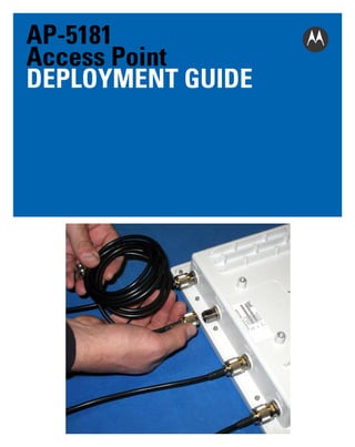
Motorola solutions ap 5181 access point deployment guide (part no. 72 e-152229-01 rev. b)
•
0 likes•522 views


Recommended
More Related Content
Similar to Motorola solutions ap 5181 access point deployment guide (part no. 72 e-152229-01 rev. b)
Similar to Motorola solutions ap 5181 access point deployment guide (part no. 72 e-152229-01 rev. b) (20)
More from Advantec Distribution
More from Advantec Distribution (20)
Recently uploaded
Recently uploaded (20)
Motorola solutions ap 5181 access point deployment guide (part no. 72 e-152229-01 rev. b)
- 2. 2 AP5181 Access Point MOTOROLA SOLUTIONS and the Stylized M Logo are registered in the US Patent & Trademark Office. © Motorola Solutions, Inc. 2011. All rights reserved. Service Information If you have a problem with your equipment, contact support for your region. Support and issue resolution is provided for products under warranty or are covered by an agreement. Contact information and web self-service is available by visiting http://supportcentral.motorola.com/. When contacting support, please provide the following information: • Serial number of the unit • Model number or product name • Software type and version number Motorola Solutions responds to calls by email or telephone within the time limits set forth in support agreements. If you purchased your Enterprise Mobility business product from a Motorola business partner, contact that business partner for support. Support Web Site The Support Central Web site, located at http://supportcentral.motorola.com/ provides information and online assistance including developer tools, software downloads, product manuals, support contact information and online repair requests.
- 3. Deployment Guide 3 Introduction This guide provides detailed hardware setup and deployment instructions for the AP-5181 model access point. The AP-5181 model access point is primarily designed for outdoor deployments, thus it has a unique set of installation instructions. Please review all the material within this document before installing the AP-5181 model access point. The purpose of this guide is to assist you in understanding the correct use and placement of the components within the AP-5181 accessory kits. Proper installation is critical to the safety of the installation, installer and others in the area of the AP-5181’s deployment. Mounting Kit and Assembly It is recommended the assembly of the AP-5181’s accessories be started, and fully staged (as described in this chapter) before the AP-5181 is moved into its final area of deployment. Installing the AP-5181’s Mounting Accessories To install the AP-5181’s mounting accessories: 1. Install the mounting bracket to the AP-5181’s rear housing using 4 short length binder head screws from the kit. Tighten securely. NOTE Take note of the earth ground boss under the bracket. This point must be properly grounded to earth to utilize this products safety features. This is a good time to add the required grounding lug or cable (not included with the AP-5181 or mounting kit).
- 4. 4 AP5181 Access Point 2. Install the AP-5181 tilt bracket onto the AP-5181’s bracket installed in step 1. Use one long binder head screw and hex nut from the kit. This will define the pivot about which the AP-5181 can be tilted. Do not over tighten the nut. 3. Install 4 short binder head screws in the 4 slots, 2 each on left and right sides of the tilt bracket. These can be tightened during this phase of the assembly. Once deployed in the field, the 4 screws should be loosened slightly to allow the AP-5181 to be tilted to level, then re-tightened.
- 5. Deployment Guide 5 4. If sliding to a small pole diameter, up to 2 ½ inches in diameter, place the pole clamps into the slots of the bracket assembled in step 3. The pole clamps can be installed into inner or outer slots to adjust for pole diameters of various sizes. 5. Install 2 long binder head screws through the two holes of one clamp into the other clamp. Direction is not important.
- 6. 6 AP5181 Access Point On each long screw, install one split washer and one wing nut. Leave them somewhat loose, as the nut, washer and screw will be loosened and re-installed in the field when mounting the AP-5181 to a Pole. NOTE The unit is ready to be moved into its deployment area and mounted onto a pole (where the AP-5181 cannot be slid over the pole end). Installing the AP-5181 on a Pole To install an AP-5181 on a pole: 1. Select the proper slot positions for the pole clamp to properly fit onto the pole. Position and hold the tilt bracket. Align each of the 2 pole clamps in position on the pole. Install 2 long binder head screws through the two holes of one clamp and into the other clamp. Direction is not important. Install one split washer and one wing nut onto each long screw. Lightly tighten the wing nut, washer and screw. Point the tilt bracket in the direction the AP-5181 is to be mounted, and tighten the wing nut, washer and screw
- 7. Deployment Guide 7 2. Install the mounting bracket onto the tilt bracket installed in step 1. Use one long binder head screw and hex nut from the kit. This will provide the pivot about which the AP-5181 can be tilted. Do not over tighten the nut. 3. Install 4 short binder head screws in the 4 slots (two each on left and right sides of the tilt bracket). Set the angle of the AP-5181 up or down as required for the installation. The 4 short binder head screws and the long screw hex nut can all be tightened to lock the unit into position.
- 8. 8 AP5181 Access Point The image displayed above has the heavy weather accessory kit installed. Whether the unit is installed with the heavy weather kit, or without it, it will be important to connect the AP-5181 to an appropriate earth ground using the earth-ground boss on the back of the unit. NOTE It is necessary to use the band clamp adapter when installing an AP-5181 on a larger diameter pole (up to 18 inches). 4. Thread the 2 band clamps through the adapter. Using both band clamps, position the adjuster screw about 6 inches from the face of the adapter. The adjuster screw can be installed to either left or right sides. 5. Mount the adapter to the tilt bracket using 2 short binder head screws. It does not matter which side is up or down, left or right. Tighten the screws securely.
- 9. Deployment Guide 9 6. Position and hold the tilt bracket and each of the band clamps onto the mounting pole. Thread the band clamp through its own adjuster screw. Ensure the band clamp is installed into it’s own adjust screw. Thread the free end of the band clamp through the adjuster. Pass through the screw, and pull the free end of the clamp until it is snug. Repeat this process for the second clamp. Point the tilt bracket in the direction the AP-5181 is to be mounted. Tighten the band clamps. Cut-off or wrap around (as displayed above) the free end of the tightened band clamp. 7. Install the AP-5181’s mounting bracket onto the tilt bracket. Use one long binder head screw and hex nut from the kit. This will provide the pivot about which the AP-5181 can be tilted. Do not over tighten the nut.
- 10. 10 AP5181 Access Point The image displayed has the heavy weather accessory kit installed. Whether the unit uses the heavy weather kit or not, remember to connect the AP-5181 to an appropriate earth ground using the earth-ground boss on the back of the unit. 8. Install 4 short binder head screws in the 4 slots (2 each on left and right sides of the tilt bracket). Set the angle of the AP-5181 up or down as required for the installation. The 4 short binder head screws, and the long screw hex nut can be tightened to lock the AP-5181into position.
- 11. Deployment Guide 11 Heavy Weather Kit Assembly To install the AP-5181 heavy weather kit: NOTE Motorola Solutions recommends the assembly of the AP-5181 heavy weather kit be started, and fully staged, before the unit is moved into the field for deployment. 1. Install 4 antenna extension cables (provided in the kit) to the AP-5181. Hand tighten. 2. Route the antenna extension cables through the cable guides on the rear of the access point. The cables cross from left to right to maximize the bend radius. Avoid any sharp bending of the cables to extend their useful life.
- 12. 12 AP5181 Access Point NOTE Note the earth ground boss on the AP-5181. This point must be properly grounded to earth to utilize this products safety features. This is a good time to add the required grounding lug or cable (not included). 3. Install the heavy weather shield. Align the 4 screw holes with the 4 mating screw bosses on the AP-5181.
- 13. Deployment Guide 13 4. Install the mounting bracket to the AP-5181’s rear housing using 4 short length binder head screws from kit. 5. The heavy weather shield is clamped between the bracket and the housing. Tighten securely. 6. Turn the unit over. On the face of the unit, remove and discard the 4 screws located in the cover of the AP-5181.
- 14. 14 AP5181 Access Point 7. Install 4 hex stand-off screws into the screw holes created with the removal of the screws in step 5. Tighten securely. 8. Install the heavy weather shield.
- 15. Deployment Guide 15 9. Align the 4 screw holes with the 4 mating screw bosses on the AP-5181 cover. 10. Install the AP-5181 mounting bracket to AP-5181 cover using 4 short length binder head screws from the kit. The front and rear shields are intentionally staggered to ensure adequate ventilation.
- 16. 16 AP5181 Access Point 11. The heavy weather protected AP-5181 is now ready for installation. Power Tap Installation The installation of the AP-5181 Power Tap (Part No. AP-PSBIAS-5181-01R) requires the services of licensed and trained electricians. The end user is solely responsible to ensure the unit is installed and maintained by properly certified personnel. Additionally, the end user is responsible the unit is installed and maintained in full compliance of local codes and standards. WARNING! DO NOT open an installed or operating Power Tap unit. Always make sure the unit is not energized before opening an installed or operating unit. Before attempting to install a Power Tap, refer to the following guidelines: • DO NOT open an installed or operating unit. Ensure the unit is not energized before opening an installed or functioning unit. • A Power Tap installation requires the services of licensed and trained electrician. • Proper unit earth grounding is required to ensure safe and proper operation. Earth grounding must comply with all specific or regional electrical codes and regulations. • Opening the Power Tap exposes high voltage wiring, and creates a shock hazard. Care must be taken to avoid introduction to the unit interior of any foreign object and/or fluids that would facilitate a shock hazard.
- 17. Deployment Guide 17 • The instructions provided herein are intended to provide useful installation guidance, and offer insight into best practices. Adherence to this guide, and the instructions herein do not ensure compliance with specific or regional electrical codes and regulations. • In all cases, specific or regional electrical codes and regulations shall govern the installation of this product. • Installation and maintenance of this product in compliance with specific or regional electrical codes and regulations is the sole responsibility of the end user. To install an AP-5181 Power Tap: 1. Remove and retain the 10 screws used to secure the Power Tap cover. 2. Remove the weather sealing cover to expose the unit’s interior. Do not remove or tamper with the sealing gasket remaining on the back housing. 3. Remove and retain the 2 terminal screws releasing the 2 solder-less ring terminals.
- 18. 18 AP5181 Access Point 4. Remove and retain the nut with a captive locking washer. This nut releases a solder-less ring terminal. 5. Loosen the gland nut on the power entry fitting. 6. Expose 6 inches of wire from the jacket. Only use wire suited for your specific installation requirements and application. Use 3 conductor wire of a gage suitable for the required wire run. 7. Feed the wire through the power fitting. Do not tighten the fitting at this time.
- 19. Deployment Guide 19 8. Using the solder-less ring terminals, strip and terminate the individual wires. 9. Expose only sufficient copper (using a solder-less terminal crimping tool) to ensure a good electrical connection. No exposed copper strands should be visible outside the terminal insulator. 10. Install the power cable ring terminals using the 2 screws and nut removed in steps 3 and 4. • Black wire to terminal L (line) • White wire to terminal N (neutral) • Green wire to terminal G (ground)
- 20. 20 AP5181 Access Point 11. Firmly tighten screws and nut. 12. Adjust the cable jacket by sliding into and out of the gland until about 1 inch remains visible inside the housing. 13. Tighten the gland nut by hand to firmly hold the cable jacket. Examine all wires to ensure there is no crimping pulling of wires or terminations.
- 21. Deployment Guide 21 14. Ensure no loose hardware is inside the housing. Check the wiring to be sure it is clear of the cover. Carefully replace the cover. Only the correct cover orientation (as displayed below) allows all screws to be properly installed. 15. Tighten all 10 screws securely. Torque all screws to 15-20 in-lbf. Hand tighten only. Do not use power tools. 16. The Power Tap can now be installed. NOTE Please locate the earth ground boss under the bracket of the Power Tap. This point must be properly grounded to earth to utilize this product’s safety features. 17. Add the required grounding lug or cable (not included with this product) the earth ground boss.
- 22. 22 AP5181 Access Point 18. Seal un-used connectors to ensure the product’s IP56 rating. 19. Locate a port cover within the AP-PSBIAS-5181-01R product package. Install the cover on the unused LAN or WAN port and hand tighten (do not use tools).
- 23. Deployment Guide 23 NOTE Locate the earth ground boss on the back of the Power Tap. This point must be properly grounded to earth to utilize this product’s safety features. If you have not already done so, this is a good time to add the required grounding lug or cable. 20. The Power-Tap can be installed using the standard AP-5181 mounting kit. The Power Tap can be installed using the integrated mounting holes. The 2 holes are provided at the top and bottom of the unit. 21. Proper mounting of the unit places the 10 screw-heads against the mounting surface, thus making un-authorized installations difficult. 22. When mounting the Power Tap on materials such as concrete or plaster, the use of wall anchors will provide an excellent holding grip. Use the Power Tap’s 2 mounting holes as a template and punch or drill holes to accept the 2 wall anchors.
- 24. 24 AP5181 Access Point Cable Connectors and Unused Connector Protection The following are the various components found in the connector kit supplied with the AP-5181. If a different connector is used (or the connector is replaced), the replacement must be IP56 certified to retain product sealing. The cable is customer provided and must be of the length required for your specific AP-5181 deployment. The cable must be rated for outdoor use and have 8 conductors. Shielding is not required for the cable used. To install the AP-5181 cabling:
- 25. Deployment Guide 25 1. Install the silicone rubber gland into the gland housing. 2. Loosely assemble the gland nut onto the gland housing. Do not tighten until the connector is fully assembled and installed into the desired AP-5181 connection port. This creates the gland assembly. 3. Install the ring seal onto the end of the flange barrel. A small amount of grease on the surfaces will hold the ring in place for the remainder of the assembly.
- 26. 26 AP5181 Access Point As an option (not displayed above), the ring seal can be inserted into the receiving threaded hole of the gland housing. The receiving threaded hole is in the hexagonal section of the gland housing stamped LTW (see the illustration under step 2). Ensure the ring seal is seated at the bottom of the threaded hole. 4. Assemble the gland assembly, finger nut, flange barrel and modular connector onto the cable. You are now ready to install the connector face gasket. NOTE The modular connector is intended to be wired specifically. It is extremely important to wire the connector per industry standards for Ethernet, non cross- over configuration). The applicable standard is TIA/EIA 568-A. 5. Remove the adhesive liner on the gasket. Slide the gasket over the connector and along the cable, with the adhesive facing the flange surface of the flange barrel.
- 27. Deployment Guide 27 6. Press the gasket into place on the plastic face with light finger pressure. Make sure the cutout of the gasket aligns with the shape of the connector pocket of the flange barrel. 7. Slide the flange barrel so the modular connector is fully seated into the connector pocket. 8. Depress the modular connector latch spring against the body of the connector to fit the connector into the pocket. 9. Insert the connector into the LAN or WAN port of the AP-5181. The connector will only plug into the port if the connector is properly orientated. Using only finger pressure, no tools.
- 28. 28 AP5181 Access Point 10. Tighten the finger nut snugly onto the port. Next, tighten the gland assembly onto the flange barrel. Finally, tighten the gland nut onto the gland assembly. When completed, the assembly will be weather resistant to IP56, and offer reasonable strain relief to the cable. NOTE Un-used connectors need to be sealed to ensure the product’s IP56 rating. 11. Locate 2 port covers, and 3 antenna connection covers within the AP-5181-13040-WWR product package. 12. Install these covers on any un-used ports and hand tighten (use no tools).
- 29. Deployment Guide 29 13. Note the earth ground boss on the back of the unit. This point must be properly grounded to earth to utilize the AP-5181’s safety features. Add the required grounding lug or cable (not included with the AP-5181) at this time. Class 1/Division 2 Product Wiring Guidelines This content is expressly intended for use by licensed and certified professional installers and personnel. Motorola Solutions is not responsible for misuse of this information, nor damages, nor injuries either directly or indirectly resulting from, or related to, the use of the information presented within. Use of this information is at the sole discretion of the professional installer, and in all cases shall be considered with priorities provided to location specific wiring codes, safety codes, and best practices established by the industry. Selection and use of installation materials not provided with the product, such as electromechanical tubing, junction/wiring boxes, wiring materials, splices/ punch-down/interface connectors, and other hardware; shall be defined and applied at the discretion of, and at the responsibility of, the professional installer, and shall be suitable for the installation environment and product use demands.
- 30. 30 AP5181 Access Point Please review this information in this section before installing an AP-5181. These instructions will assist you in understanding the correct use and placement of all the various parts contained within the Accessory Kits. Proper installation is critical to the safety of the installation, installer and others in the area of the products use. Prior to any product wiring, Motorola Solutions strongly recommends the product components be mounted in the desired locations, and required interconnecting wiring components, such as electromechanical tubing, junction/wiring boxes, wiring materials, splices/ punch-down/interface connectors, and other hardware be provided and installed. Pig-tail cable ends as provided on the AP-5181-1304C-WR product should be routed to an acceptable junction box with sufficient space for reasonable splicing or termination. The AP-5181-1304C-WR has two cables extending from sealed wiring glands. A black plastic console port cover protects the console port during product configuration. • Do not loosen or remove the wiring glands, these are factory sealed to ensure a gas tight interface to the product. • The glands are designed to be threaded directly into infrastructure protective cable armor, splicing and wiring boxes, selected by the professional installer and suitable for the installation environment. • Do not remove the plastic console port cover on an installed product. Use of the console port is restricted to protected and non-hazardous environments only. • The yellow colored cable is the data cable containing 4 pairs, 8 wires. • No Power Is Provided or Accepted Over the Data wires of this product. • The grey colored cable is the power cable containing 1 pair, 2 wires. Expose and strip as required for splicing to the infrastructure wiring the AP power wires of the grey power cable.
- 31. Deployment Guide 31 • The product is intended to be connected and is certified with the AP-PSBIAS-5181-C-R product. Use of any other power supply voids all certifications and warranties. • The blue wire is connected to the positive terminal of the AP-PSBIAS-5181-C-R 48VDC power supply. • The brown wire is connected to the negative terminal of the AP-PSBIAS-5181-C-R 48VDC power supply. • The professional installer is required to select the appropriate interconnecting length and gauge of cable, protective cable armor, splicing materials, junction/wiring boxes, suitable for the installation environment. The AP-PSBIAS-5181-C-R is the only power supply certified for use with the AP-5181-1304C-WR. The use of any other supply is not approved and may expose the installation to significant damage risk, personal injury or death. Remove and retain the 10 screws for the power supply cover to expose the internal components. The 48VDC terminal used to connect to and power the AP-5181-1304C-WR is as follows.
- 32. 32 AP5181 Access Point Two brass wiring glands are included with the AP-PSBIAS-5181-C-R. Instructions display below for a single gland installation, but both glands are installed in the same manner. The installer shall disassemble the glands and retain any loose components within the gland. The top portion of the gland is installed into the AP-PSBIAS-5181-C-R threaded boss and tightened to 8-10ft-lbs. Note that the long threaded end of the gland is threaded into the plastic boss. The bottom of the gland is then loosely re-assembled to the top of the gland. Note the installation orientation of the compression sleeve (beveled edge orients into bottom side of gland, the flat end is placed against washer) and compression washer.
- 33. Deployment Guide 33 Strip to length and install the interconnecting cable through the body of the gland. Tighten the gland bottom against the gland top and torque to 10-15ft.-lb. It’s required the top of the gland be restrained against turning by an appropriate tool while applying torque to the bottom of the gland. Failure to do so will result in the cracking of the AP-PSBIAS-5181-C-R plastic boss. With both glands tightened against the cable, terminate the 48VDC and AC supply cable to the terminal screws as required for both the installation and code. The glands are designed to be threaded directly into the infrastructure’s protective cable armor, splicing and wiring boxes. Ensure they’re selected by the professional installer and suitable for the installation environment. Class 1/Division 2 Data Wiring Guide Please review this information in this section before installing an AP-5181. These instructions will assist you in understanding the correct use and placement of all the various parts contained within the Accessory Kits. Proper installation is critical to the safety of the installation, installer and others in the area of the products use. Prior to any product wiring, Motorola Solutions strongly recommends the product components be mounted in the desired locations, and required interconnecting wiring components, such as electromechanical tubing, junction/wiring boxes, wiring materials, splices/ punch-down/interface connectors, and other hardware be provided and installed. Pig-tail cable ends as provided on the AP-5181-1304C-WR product should be routed to an acceptable junction box with sufficient space for reasonable splicing or termination.
- 34. 34 AP5181 Access Point The AP-5181-1304C-WR has two cables extending from sealed wiring glands. A black plastic console port cover protects the console port during product configuration. • Do not loosen or remove the wiring glands, these are factory sealed to ensure a gas tight interface to the product. • The glands are designed to be threaded directly into infrastructure protective cable armor, splicing and wiring boxes, selected by the professional installer and suitable for the installation environment. • Do not remove the plastic console port cover on an installed product. Use of the console port is restricted to protected and non-hazardous environments only. • The yellow colored cable is the data cable containing 4 pairs, 8 wires. • No Power Is Provided or Accepted Over the Data wires of this product. • The grey colored cable is the power cable containing 1 pair, 2 wires. Expose and strip as required for splicing to the infrastructure wiring the AP power wires of the yellow power cable.
- 35. Deployment Guide 35 Strip away a length of the yellow cable jacket and cable braid to expose 4 internally shielded cable pairs. The wire pairs are intended to be used with a site suitable punch-down block, and spliced to the infrastructure data cables. Wiring color codes and pairing are compatible with Ethernet Standard T568A, as noted in the following: • Green = Transmit - • White paired with Green = Transmit + • Orange = Receive - • White paired with Orange = Receive + • Brown and Blue pairs are not used A professional installer is required to select the appropriate interconnecting length and cable gauge, protective cable armor, splicing materials and junction/wiring boxes suitable for the installation environment. Suitable Ethernet punch down connections are available commercially to the installer. The following (on the next several pages) is provided as a reference example for commercially available materials. The following describes a method of splicing the product data cable into a modular connector suitable for direct connection to a RJ45 modular plug terminated Ethernet cable. The professional installer is expected to identify the appropriate punch down connection for the installation environment and junction box constraints. The professional installer is expected to meet all relevant electrical and safety codes.
- 36. 36 AP5181 Access Point
- 37. Deployment Guide 37
- 38. 38 AP5181 Access Point
- 39. Deployment Guide 39
- 40. Motorola Solutions, Inc. 1301 E. Algonquin Rd. Schaumburg, IL 60196-1078, U.S.A. http://www.motorolasolutions.com MOTOROLA, MOTO, MOTOROLA SOLUTIONS and the Stylized M Logo are trademarks or registered trademarks of Motorola Trademark Holdings, LLC and are used under license. All other trademarks are the property of their respective owners. © 2011 Motorola Solutions, Inc. All Rights Reserved. 72E-152470-01 Revision A - May 2011