SlideShare a Scribd company logo
1 of 17
Download to read offline
2.5. FINITE STATE MACHINES IN VHDL                                                                                                                       123


2.5 Finite State Machines in VHDL
2.5.1 Introduction to State-Machine Design

2.5.1.1 Mealy vs Moore State Machines

Moore Machines       ..................................................................... .


                                                                                                                   s0/0

                                                                                                               a            !a

• Outputs are dependent upon only the state
                                                                                                        s1/1                  s2/0
• No combinational paths from inputs to outputs


                                                                                                                   s3/0


Mealy Machines      . . . . . . . . . . . . . . . . . . . . . . . . . . . . . . . . . . . . . . . . . . . . . . . . . . . . . . . . . . . . . . . . . . . . . ..


                                                                                                                     s0

                                                                                                            a/1             !a/0
• Outputs are dependent upon both the state and the in-
  puts                                                                                                    s1                     s2
• Combinational paths from inputs to outputs
                                                                                                             /0             /0

                                                                                                                     s3


2.5.1.2 Introduction to State Machines and VHDL

A state machine is generally written as a single clocked process, or as a pair of processes, where
one is clocked and one is combinational.
124                                                     CHAPTER 2. RTL DESIGN WITH VHDL


Design Decisions      ..................................................................... .

•   Moore vs Mealy (Sections 2.5.2 and 2.5.3)
•   Implicit vs Explicit (Section 2.5.1.3)
•   State values in explicit state machines: Enumerated type vs constants (Section 2.5.5.1)
•   State values for constants: encoding scheme (binary, gray, one-hot, ...) (Section 2.5.5)


VHDL Constructs for State Machines           ..................................................


The following VHDL control constructs are useful to steer the transition from state to state:

•   if ... then ...            else                 • loop
•   case                                            • next
•   for ... loop                                    • exit
•   while ... loop


2.5.1.3 Explicit vs Implicit State Machines

There are two broad styles of writing state machines in VHDL: explicit and implicit. “Explicit”
and “implicit” refer to whether there is an explicit state signal in the VHDL code. Explicit state
machines have a state signal in the VHDL code. Implicit state machines do not contain a state
signal. Instead, they use VHDL processes with multiple wait statements to control the execution.
In the explicit style of writing state machines, each process has at most one wait statement. For
the explicit style of writing state machines, there are two sub-categories: “current state” and “cur-
rent+next state”.
In the explicit-current style of writing state machines, the state signal represents the current state
of the machine and the signal is assigned its next value in a clocked process.
In the explicit-current+next style, there is a signal for the current state and another signal for the
next state. The next-state signal is assigned its value in a combinational process or concurrent state-
ment and is dependent upon the current state and the inputs. The current-state signal is assigned
its value in a clocked process and is just a flopped copy of the next-state signal.
For the implicit style of writing state machines, the synthesis program adds an implicit register to
hold the state signal and combinational circuitry to update the state signal. In Synopsys synthesis
tools, the state signal defined by the synthesizer is named multiple wait state reg.
In Mentor Graphics, the state signal is named STATE VAR
We can think of the VHDL code for implicit state machines as having zero state signals, explicit-
current state machines as having one state signal (state), and explicit-current+next state ma-
chines as having two state signals (state and state next).
2.5.2 Implementing a Simple Moore Machine                                                         125


As with all topics in E&CE 327, there are tradeoffs between these different styles of writing state
machines. Most books teach only the explicit-current+next style. This style is the style closest to
the hardware, which means that they are more amenable to optimization through human interven-
tion, rather than relying on a synthesis tool for optimization. The advantage of the implicit style is
that they are concise and readable for control flows consisting of nested loops and branches (e.g.
the type of control flow that appears in software). For control flows that have less structure, it
can be difficult to write an implicit state machine. Very few books or synthesis manuals describe
multiple-wait statement processes, but they are relatively well supported among synthesis tools.

Because implicit state machines are written with loops, if-then-elses, cases, etc. it is difficult to
write some state machines with complicated control flows in an implicit style. The following
example illustrates the point.
                                                     a
                                          s0/0                s2/0
                                                 !a


                                          !a     a
                                          s3/0                s1/1


         Note:      The terminology of “explicit” and “implicit” is somewhat standard,
         in that some descriptions of processes with multiple wait statements describe
         the processes as having “implicit state machines”.
         There is no standard terminology to distinguish between the two explicit styles:
         explicit-current+next and explicit-current.


2.5.2 Implementing a Simple Moore Machine


                     s0/0
                                                         entity simple is
                 a          !a                             port (
                                                             a, clk : in std_logic;
              s1/1           s2/0                            z : out std_logic
                                                           );
                                                         end simple;

                     s3/0
126                                    CHAPTER 2. RTL DESIGN WITH VHDL


2.5.2.1 Implicit Moore State Machine

                                                   Flops      3
architecture moore_implicit_v1a of simple is       Gates      2
begin                                              Delay 1 gate
  process
  begin
    z <= ’0’;
    wait until rising_edge(clk);
    if (a = ’1’) then
      z <= ’1’;
    else
      z <= ’0’;
    end if;
    wait until rising_edge(clk);
    z <= ’0’;
    wait until rising_edge(clk);
  end process;
end moore_implicit;


                                                                    !a
                                                             s2/0
2.5.2 Implementing a Simple Moore Machine                     127


2.5.2.2 Explicit Moore with Flopped Output

architecture moore_explicit_v1 of simple is
  type state_ty is (s0, s1, s2, s3);          Flops       3
  signal state : state_ty;                    Gates     10
begin                                         Delay 3 gates
  process (clk)
  begin
    if rising_edge(clk) then
      case state is
        when s0 =>
          if (a = ’1’) then
            state <= s1;
            z     <= ’1’;
          else
            state <= s2;
            z     <= ’0’;
          end if;
        when s1 | s2 =>
          state <= s3;
          z     <= ’0’;
        when s3 =>
          state <= s0;
          z     <= ’1’;
      end case;
    end if;
  end process;
end moore_explicit_v1;
128                                           CHAPTER 2. RTL DESIGN WITH VHDL


2.5.2.3 Explicit Moore with Combinational Outputs

                                                          Flops       2
architecture moore_explicit_v2 of simple is               Gates       7
  type state_ty is (s0, s1, s2, s3);                      Delay 4 gates
  signal state : state_ty;
begin
  process (clk)
  begin
    if rising_edge(clk) then
      case state is
        when s0 =>
          if (a = ’1’) then
            state <= s1;
          else
            state <= s2;
          end if;
        when s1 | s2 =>
          state <= s3;
        when s3 =>
          state <= s0;
      end case;
    end if;
  end process;
  z <=   ’1’ when (state = s1)
    else ’0’;
end moore_explicit_v2;
2.5.2 Implementing a Simple Moore Machine                                                129


2.5.2.4 Explicit-Current+Next Moore with Concurrent Assignment

                                                                   Flops 2
architecture moore_explicit_v3 of simple is                        Gates 7
  type state_ty is (s0, s1, s2, s3);                               Delay 4
  signal state, state_nxt : state_ty;
begin
  process (clk)
  begin
    if rising_edge(clk) then
      state <= state_nxt;
    end if;
  end process;
  state_nxt <=   s1 when (state = s0) and (a = ’1’)
            else s2 when (state = s0) and (a = ’0’)
            else s3 when (state = s1) or (state = s2)
            else s0;
  z <=   ’1’ when (state = s1)
    else ’0’;
end moore_explicit_v3;

The hardware synthesized from this architecture is the same as that synthesized from moore explicit v2,
which is written in the current-explicit style.
130                                           CHAPTER 2. RTL DESIGN WITH VHDL


2.5.2.5 Explicit-Current+Next Moore with Combinational Process

architecture moore_explicit_v4 of simple is                 For this architecture, we
  type state_ty is (s0, s1, s2, s3);                        change the selected assign-
  signal state, state_nxt : state_ty;                       ment to state into a combi-
begin                                                       national process using a case
  process (clk)                                             statement.
  begin
    if rising_edge(clk) then                                 Flops 2
      state <= state_nxt;                                    Gates 7
    end if;                                                  Delay 4
  end process;
  process (state, a)                                        The       hardware    synthe-
  begin                                                     sized     from this archi-
    case state is                                           tecture    is the same as
      when s0 =>                                            that      synthesized   from
        if (a = ’1’) then                                   moore     explicit v2 and
          state_nxt <= s1;                                  v3.
        else
          state_nxt <= s2;
        end if;
      when s1 | s2 =>
        state_nxt <= s3;
      when s3 =>
        state_nxt <= s0;
    end case;
  end process;
  z <=   ’1’ when (state = s1)
    else ’0’;
end moore_explicit_v4;
2.5.3 Implementing a Simple Mealy Machine                                                    131


2.5.3 Implementing a Simple Mealy Machine

Mealy machines have a combinational path from inputs to outputs, which often violates good
coding guidelines for hardware. Thus, Moore machines are much more common. You should
know how to write a Mealy machine if needed, but most of the state machines that you design will
be Moore machines.

This is the same entity as for the simple Moore state machine. The behaviour of the Mealy machine
is the same as the Moore machine, except for the timing relationship between the output (z) and
the input (a).


                     s0
                                                entity simple is
               a/1        !a/0                    port (
                                                    a, clk : in std_logic;
              s1               s2                   z : out std_logic
                                                  );
                /0        /0                    end simple;

                     s3
132                                                   CHAPTER 2. RTL DESIGN WITH VHDL


2.5.3.1 Implicit Mealy State Machine

         Note:     An implicit Mealy state machine is nonsensical.

In an implicit state machine, we do not have a state signal. But, as the example below illustrates,
to create a Mealy state machine we must have a state signal.

An implicit style is a nonsensical choice for Mealy state machines. Because the output is depen-
dent upon the input in the current clock cycle, the output cannot be a flop. For the output to be
combinational and dependent upon both the current state and the current input, we must create a
state signal that we can read in the assignment to the output. Creating a state signal obviates the
advantages of using an implicit style of state machine.

                                                                       Flops       4
architecture implicit_mealy of simple is                               Gates       8
  type state_ty is (s0, s1, s2, s3);                                   Delay 2 gates
  signal state : state_ty;
begin
  process
  begin
    state <= s0;
    wait until rising_edge(clk);
    if (a = ’1’) then
      state <= s1;
    else
      state <= s2;
    end if;
    wait until rising_edge(clk);
    state <= s3;
    wait until rising_edge(clk);
  end process;
  z <=   ’1’ when (state = s0) and a = ’1’
    else ’0;
end mealy_implicit;
                                                                                          /0


                                                                                                      !a/0
                                                                                                 s2
2.5.3 Implementing a Simple Mealy Machine              133


2.5.3.2 Explicit Mealy State Machine

                                             Flops 2
architecture mealy_explicit of simple is     Gates 7
  type state_ty is (s0, s1, s2, s3);         Delay 3
  signal state : state_ty;
begin
  process (clk)
  begin
    if rising_edge(clk) then
      case state is
        when s0 =>
          if (a = ’1’) then
            state <= s1;
          else
            state <= s2;
          end if;
        when s1 | s2 =>
          state <= s3;
        when others =>
          state <= s0;
      end case;
    end if;
  end process;
  z <=   ’1’ when (state = s0) and a = ’1’
    else ’0’;
end mealy_explicit;
134                                                    CHAPTER 2. RTL DESIGN WITH VHDL


2.5.3.3 Explicit-Current+Next Mealy

                                                                         Flops 2
architecture mealy_explicit_v2 of simple is                              Gates 4
  type state_ty is (s0, s1, s2, s3);                                     Delay 3
  signal state, state_nxt : state_ty;
begin
  process (clk)
  begin
    if rising_edge(clk) then
      state <= state_nxt;
    end if;
  end process;
  state_nxt <=   s1 when (state = s0) and a = ’1’
            else s2 when (state = s0) and a = ’0’
            else s3 when (state = s1) or (state = s2)
            else s0;
  z <=   ’1’ when (state = s0) and a = ’1’
    else ’0’;
end mealy_explicit_v2;

For the Mealy machine, the explicit-current+next style is smaller than the the explicit-current style.
In contrast, for the Moore machine, the two styles produce exactly the same hardware.
2.5.4 Reset                                                                                                                        135


2.5.4 Reset

All circuits should have a reset signal that puts the circuit back into a good initial state. However,
not all flip flops within the circuit need to be reset. In a circuit that has a datapath and a state
machine, the state machine will probably need to be reset, but datapath may not need to be reset.

There are standard ways to add a reset signal to both explicit and implicit state machines.

It is important that reset is tested on every clock cycle, otherwise a reset might not be noticed, or
your circuit will be slow to react to reset and could generate illegal outputs after reset is asserted.


Reset with Implicit State Machine        . . .. . . . . .. . . . . .. . . . . .. . . . . .. . . . . .. . . . . .. . . . . . .. . . . . ...


With an implicit state machine, we need to insert a loop in the process and test for reset after each
wait statement.

Here is the implicit Moore machine from section 2.5.2.1 with reset code added in bold.

architecture moore_implicit of simple is
begin
  process
  begin
    init : loop                      -- outermost loop
      z <= ’0’;
      wait until rising_edge(clk);
      next init when (reset = ’1’); -- test for reset
      if (a = ’1’) then
        z <= ’1’;
      else
        z <= ’0’;
      end if;
      wait until rising_edge(clk);
      next init when (reset = ’1’); -- test for reset
      z <= ’0’;
      wait until rising_edge(clk);
      next init when (reset = ’1’); -- test for reset
  end process;
end moore_implicit;
136                                                    CHAPTER 2. RTL DESIGN WITH VHDL


Reset with Explicit State Machine       ......................................................


Reset is often easier to include in an explicit state machine, because we need only put a test for
reset = ’1’ in the clocked process for the state.
The pattern for an explicit-current style of machine is:
  process (clk) begin
    if rising_edge(clk) then
      if reset = ’1’ then
        state <= S0;
      else
        if ... then
          state <= ...;
        elif ... then
          ... -- more tests and assignments to state
        end if;
      end if;
    end if;
  end process;
Applying this pattern to the explicit Moore machine from section 2.5.2.3 produces:
architecture moore_explicit_v2 of simple is
  type state_ty is (s0, s1, s2, s3);
  signal state : state_ty;
begin
  process (clk)
  begin
    if rising_edge(clk) then
      if (reset = ’1’) then
        state <= s0;
      else
        case state is
           when s0 =>
            if (a = ’1’) then
              state <= s1;
            else
              state <= s2;
            end if;
          when s1 | s2 =>
            state <= s3;
          when s3 =>
            state <= s0;
        end case;
      end if;
    end if;
  end process;
  z <=   ’1’ when (state = s1)
    else ’0’;
end moore_explicit_v2;
2.5.5 State Encoding                                                                           137


The pattern for an explicit-current+next style is:

  process (clk) begin
    if rising_edge(clk) then
      if reset = ’1’ then
        state_cur <= reset state;
      else
        state_cur <= state_nxt;
      end if;
    end if;
  end process;


2.5.5 State Encoding

When working with explicit state machines, we must address the issue of state encoding: what
bit-vector value to associate with each state?

With implicit state machines, we do not need to worry about state encoding. The synthesis program
determines the number of states and the encoding for each state.


2.5.5.1 Constants vs Enumerated Type

Using an enumerated type, the synthesis tools chooses the encoding:

  type state_ty is (s0, s1, s2, s3);
  signal state : state_ty;
Using constants, we choose the encoding:

  type state_ty is std_logic_vector(1 downto 0);
  constant s0 : state_ty := "11";
  constant s1 : state_ty := "10";
  constant s2 : state_ty := "00";
  constant s3 : state_ty := "01";
  signal state : state_ty;


Providing Encodings for Enumerated Types             ............................................


Many synthesizers allow the user to provide hints on how to encode the states, or allow the user to
provide explicitly the desire encoding. These hints are done either through VHDL attributes
or special comments in the code.
138                                                      CHAPTER 2. RTL DESIGN WITH VHDL


Simulation     ............................................................................


When doing functional simulation with enumerated types, simulators often display waveforms
with “pretty-printed” values rather than bits (e.g. s0 and s1 rather than 11 and 10). However,
when simulating a design that has been mapped to gates, the enumerated type dissappears and you
are left with just bits. If you don’t know the encoding that the synthesis tool chose, it can be very
difficult to debug the design.

However, this opens you up to potential bugs if the enumerated type you are testing grows to
include more values, which then end up unintentionally executing your when other branch,
rather than having a special branch of their own in the case statement.


Unused Values       ....................................................................... .


If the number of values you have in your datatype is not a power of two, then you will have some
unused values that are representable.

For example:

  type state_ty is std_logic_vector(2 downto 0);
  constant s0 : state_ty := "011";
  constant s1 : state_ty := "000";
  constant s2 : state_ty := "001";
  constant s3 : state_ty := "011";
  constant s4 : state_ty := "101";
  signal state : state_ty;
This type only needs five unique values, but can represent eight different values. What should we
do with the three representable values that we don’t need? The safest thing to do is to code your
design so that if an illegal value is encountered, the machine resets or enters an error state.


2.5.5.2 Encoding Schemes
• Binary: Conventional binary counter.
• One-hot: Exactly one bit is asserted at any time.
• Modified one-hot: Altera’s Quartus synthesizer generates an almost-one-hot encoding where the
  bit representing the reset state is inverted. This means that the reset state is all ’O’s and all other
  states have two ’1’s: one for the reset state and one for the current state.
• Gray: Transition between adjacent values requires exactly one bit flip.
• Custom: Choose encoding to simplify combinational logic for specific task.
2.6. DATAFLOW DIAGRAMS                                                                          139


Tradeoffs in Encoding Schemes        ....................................................... .

• Gray is good for low-power applications where consecutive data values typically differ by 1 (e.g.
  no random jumps).
• One-hot usually has less combinational logic and runs faster than binary for machines with up
  to a dozen or so states. With more than a dozen states, the extra flip-flops required by one-hot
  encoding become too expensive.
• Custom is great if you have lots of time and are incredibly intelligent, or have deep insight into
  the guts of your design.
         Note: Don’t care values When we don’t care what is the value of a signal we
         assign the signal ’-’, which is “don’t care” in VHDL. This should allow the
         synthesis tool to use whatever value is most helpful in simplifying the Boolean
         equations for the signal (e.g. Karnaugh maps). In the past, some groups in
         E&CE 327 have used ’-’ quite succesfuly to decrease the area of their design.
         However, a few groups found that using ’-’ increased the size of their design,
         when they were expecting it to decrease the size. So, if you are tweaking your
         design to squeeze out the last few unneeded FPGA cells, pay close attention as
         to whether using ’-’ hurts or helps.


2.6 Dataflow Diagrams
2.6.1 Dataflow Diagrams Overview
• Dataflow diagrams are data-dependency graphs where the computation is divided into clock
  cycles.
• Purpose:
  – Provide a disciplined approach for designing datapath-centric circuits
  – Guide the design from algorithm, through high-level models, and finally to register transfer
    level code for the datapath and control circuitry.
  – Estimate area and performance
  – Make tradeoffs between different design options
• Background
  – Based on techniques from high-level synthesis tools
  – Some similarity between high-level synthesis and software compilation
  – Each dataflow diagram corresponds to a basic block in software compiler terminology.

More Related Content

What's hot

All VLSI programs
All VLSI programsAll VLSI programs
All VLSI programs
Gouthaman V
 

What's hot (20)

Serial Communication & Embedded System Interface
Serial Communication & Embedded System InterfaceSerial Communication & Embedded System Interface
Serial Communication & Embedded System Interface
 
Embedded systems - UNIT-1 - Mtech
Embedded systems - UNIT-1 - MtechEmbedded systems - UNIT-1 - Mtech
Embedded systems - UNIT-1 - Mtech
 
CPU Verification
CPU VerificationCPU Verification
CPU Verification
 
Hardware-Software Codesign
Hardware-Software CodesignHardware-Software Codesign
Hardware-Software Codesign
 
Basics of vlsi
Basics of vlsiBasics of vlsi
Basics of vlsi
 
Verilog HDL
Verilog HDLVerilog HDL
Verilog HDL
 
Lect 7: Verilog Behavioral model for Absolute Beginners
Lect 7: Verilog Behavioral model for Absolute BeginnersLect 7: Verilog Behavioral model for Absolute Beginners
Lect 7: Verilog Behavioral model for Absolute Beginners
 
Verilog operators.pptx
Verilog  operators.pptxVerilog  operators.pptx
Verilog operators.pptx
 
2. block diagram and components of embedded system
2. block diagram and components of embedded system2. block diagram and components of embedded system
2. block diagram and components of embedded system
 
SoC Design
SoC DesignSoC Design
SoC Design
 
Actel fpga
Actel fpgaActel fpga
Actel fpga
 
ARM - Advance RISC Machine
ARM - Advance RISC MachineARM - Advance RISC Machine
ARM - Advance RISC Machine
 
TMS320C5x
TMS320C5xTMS320C5x
TMS320C5x
 
Plc (programming)
Plc (programming)Plc (programming)
Plc (programming)
 
CMOS LOGIC STRUCTURES
CMOS LOGIC STRUCTURESCMOS LOGIC STRUCTURES
CMOS LOGIC STRUCTURES
 
VHDL- data types
VHDL- data typesVHDL- data types
VHDL- data types
 
Introduction to dsp
Introduction to dspIntroduction to dsp
Introduction to dsp
 
All VLSI programs
All VLSI programsAll VLSI programs
All VLSI programs
 
Xilinx 4000 series
Xilinx 4000 seriesXilinx 4000 series
Xilinx 4000 series
 
Introduction to embedded systems
Introduction  to embedded systemsIntroduction  to embedded systems
Introduction to embedded systems
 

Viewers also liked (15)

Mealy machine
Mealy machineMealy machine
Mealy machine
 
Mgd finite statemachine
Mgd finite statemachineMgd finite statemachine
Mgd finite statemachine
 
16%20 lecture
16%20 lecture16%20 lecture
16%20 lecture
 
States machine
States machineStates machine
States machine
 
Pattern detection in mealy machine
Pattern detection in mealy machinePattern detection in mealy machine
Pattern detection in mealy machine
 
Example of finite state machine diagram
Example of finite state machine diagramExample of finite state machine diagram
Example of finite state machine diagram
 
Finite State Machines
Finite State Machines Finite State Machines
Finite State Machines
 
Finite state machines
Finite state machinesFinite state machines
Finite state machines
 
Session six
Session sixSession six
Session six
 
Mealy state machine
Mealy state machineMealy state machine
Mealy state machine
 
Synchronous state machines. Moore and Mealy state machines (FSM)
Synchronous state machines.  Moore and Mealy state machines (FSM)Synchronous state machines.  Moore and Mealy state machines (FSM)
Synchronous state machines. Moore and Mealy state machines (FSM)
 
Moore and mealy machines
Moore and mealy machinesMoore and mealy machines
Moore and mealy machines
 
Cldch8
Cldch8Cldch8
Cldch8
 
model-analysis
 model-analysis model-analysis
model-analysis
 
Data Encoding
Data EncodingData Encoding
Data Encoding
 

Similar to VHDL Reference - FSM

Packet Tracer Simulation Lab Layer 2 Switching
Packet Tracer Simulation Lab Layer 2 SwitchingPacket Tracer Simulation Lab Layer 2 Switching
Packet Tracer Simulation Lab Layer 2 Switching
Johnson Liu
 
Bharath Ram Chandrasekar_Tele 6603_SDN &NFV
Bharath Ram Chandrasekar_Tele 6603_SDN &NFVBharath Ram Chandrasekar_Tele 6603_SDN &NFV
Bharath Ram Chandrasekar_Tele 6603_SDN &NFV
Bharath Ram Chandrasekar
 

Similar to VHDL Reference - FSM (20)

Mealy machine
Mealy machineMealy machine
Mealy machine
 
Modeling FSMs
Modeling FSMsModeling FSMs
Modeling FSMs
 
Writing more complex models (continued)
Writing more complex models (continued)Writing more complex models (continued)
Writing more complex models (continued)
 
verilog_fsm.pdf
verilog_fsm.pdfverilog_fsm.pdf
verilog_fsm.pdf
 
Verilog_ppt.pdf
Verilog_ppt.pdfVerilog_ppt.pdf
Verilog_ppt.pdf
 
sunil jha presentation.pptx
sunil jha presentation.pptxsunil jha presentation.pptx
sunil jha presentation.pptx
 
Packet Tracer Simulation Lab Layer 2 Switching
Packet Tracer Simulation Lab Layer 2 SwitchingPacket Tracer Simulation Lab Layer 2 Switching
Packet Tracer Simulation Lab Layer 2 Switching
 
Basic-VHDL-Constructs1.ppt
Basic-VHDL-Constructs1.pptBasic-VHDL-Constructs1.ppt
Basic-VHDL-Constructs1.ppt
 
Combinational Circuits
Combinational CircuitsCombinational Circuits
Combinational Circuits
 
Intro
IntroIntro
Intro
 
Akka Cluster in Production
Akka Cluster in ProductionAkka Cluster in Production
Akka Cluster in Production
 
CCNP Study Guide
CCNP Study GuideCCNP Study Guide
CCNP Study Guide
 
07 seq logicii-ix2
07 seq logicii-ix207 seq logicii-ix2
07 seq logicii-ix2
 
Writing more complex models
Writing more complex modelsWriting more complex models
Writing more complex models
 
A meta model supporting both hardware and smalltalk-based execution of FPGA c...
A meta model supporting both hardware and smalltalk-based execution of FPGA c...A meta model supporting both hardware and smalltalk-based execution of FPGA c...
A meta model supporting both hardware and smalltalk-based execution of FPGA c...
 
Packettracersimulationlabl3routing 130306235157-phpapp02
Packettracersimulationlabl3routing 130306235157-phpapp02Packettracersimulationlabl3routing 130306235157-phpapp02
Packettracersimulationlabl3routing 130306235157-phpapp02
 
Session1
Session1Session1
Session1
 
Reactive mistakes reactive nyc
Reactive mistakes   reactive nycReactive mistakes   reactive nyc
Reactive mistakes reactive nyc
 
Bharath Ram Chandrasekar_Tele 6603_SDN &NFV
Bharath Ram Chandrasekar_Tele 6603_SDN &NFVBharath Ram Chandrasekar_Tele 6603_SDN &NFV
Bharath Ram Chandrasekar_Tele 6603_SDN &NFV
 
Kroening et al, v2c a verilog to c translator
Kroening et al, v2c   a verilog to c translatorKroening et al, v2c   a verilog to c translator
Kroening et al, v2c a verilog to c translator
 

Recently uploaded

Jual Obat Aborsi Hongkong ( Asli No.1 ) 085657271886 Obat Penggugur Kandungan...
Jual Obat Aborsi Hongkong ( Asli No.1 ) 085657271886 Obat Penggugur Kandungan...Jual Obat Aborsi Hongkong ( Asli No.1 ) 085657271886 Obat Penggugur Kandungan...
Jual Obat Aborsi Hongkong ( Asli No.1 ) 085657271886 Obat Penggugur Kandungan...
ZurliaSoop
 
Salient Features of India constitution especially power and functions
Salient Features of India constitution especially power and functionsSalient Features of India constitution especially power and functions
Salient Features of India constitution especially power and functions
KarakKing
 
The basics of sentences session 3pptx.pptx
The basics of sentences session 3pptx.pptxThe basics of sentences session 3pptx.pptx
The basics of sentences session 3pptx.pptx
heathfieldcps1
 

Recently uploaded (20)

Micro-Scholarship, What it is, How can it help me.pdf
Micro-Scholarship, What it is, How can it help me.pdfMicro-Scholarship, What it is, How can it help me.pdf
Micro-Scholarship, What it is, How can it help me.pdf
 
Exploring_the_Narrative_Style_of_Amitav_Ghoshs_Gun_Island.pptx
Exploring_the_Narrative_Style_of_Amitav_Ghoshs_Gun_Island.pptxExploring_the_Narrative_Style_of_Amitav_Ghoshs_Gun_Island.pptx
Exploring_the_Narrative_Style_of_Amitav_Ghoshs_Gun_Island.pptx
 
HMCS Vancouver Pre-Deployment Brief - May 2024 (Web Version).pptx
HMCS Vancouver Pre-Deployment Brief - May 2024 (Web Version).pptxHMCS Vancouver Pre-Deployment Brief - May 2024 (Web Version).pptx
HMCS Vancouver Pre-Deployment Brief - May 2024 (Web Version).pptx
 
Jual Obat Aborsi Hongkong ( Asli No.1 ) 085657271886 Obat Penggugur Kandungan...
Jual Obat Aborsi Hongkong ( Asli No.1 ) 085657271886 Obat Penggugur Kandungan...Jual Obat Aborsi Hongkong ( Asli No.1 ) 085657271886 Obat Penggugur Kandungan...
Jual Obat Aborsi Hongkong ( Asli No.1 ) 085657271886 Obat Penggugur Kandungan...
 
NO1 Top Black Magic Specialist In Lahore Black magic In Pakistan Kala Ilam Ex...
NO1 Top Black Magic Specialist In Lahore Black magic In Pakistan Kala Ilam Ex...NO1 Top Black Magic Specialist In Lahore Black magic In Pakistan Kala Ilam Ex...
NO1 Top Black Magic Specialist In Lahore Black magic In Pakistan Kala Ilam Ex...
 
Interdisciplinary_Insights_Data_Collection_Methods.pptx
Interdisciplinary_Insights_Data_Collection_Methods.pptxInterdisciplinary_Insights_Data_Collection_Methods.pptx
Interdisciplinary_Insights_Data_Collection_Methods.pptx
 
Application orientated numerical on hev.ppt
Application orientated numerical on hev.pptApplication orientated numerical on hev.ppt
Application orientated numerical on hev.ppt
 
Salient Features of India constitution especially power and functions
Salient Features of India constitution especially power and functionsSalient Features of India constitution especially power and functions
Salient Features of India constitution especially power and functions
 
Accessible Digital Futures project (20/03/2024)
Accessible Digital Futures project (20/03/2024)Accessible Digital Futures project (20/03/2024)
Accessible Digital Futures project (20/03/2024)
 
How to Create and Manage Wizard in Odoo 17
How to Create and Manage Wizard in Odoo 17How to Create and Manage Wizard in Odoo 17
How to Create and Manage Wizard in Odoo 17
 
80 ĐỀ THI THỬ TUYỂN SINH TIẾNG ANH VÀO 10 SỞ GD – ĐT THÀNH PHỐ HỒ CHÍ MINH NĂ...
80 ĐỀ THI THỬ TUYỂN SINH TIẾNG ANH VÀO 10 SỞ GD – ĐT THÀNH PHỐ HỒ CHÍ MINH NĂ...80 ĐỀ THI THỬ TUYỂN SINH TIẾNG ANH VÀO 10 SỞ GD – ĐT THÀNH PHỐ HỒ CHÍ MINH NĂ...
80 ĐỀ THI THỬ TUYỂN SINH TIẾNG ANH VÀO 10 SỞ GD – ĐT THÀNH PHỐ HỒ CHÍ MINH NĂ...
 
Understanding Accommodations and Modifications
Understanding  Accommodations and ModificationsUnderstanding  Accommodations and Modifications
Understanding Accommodations and Modifications
 
Unit 3 Emotional Intelligence and Spiritual Intelligence.pdf
Unit 3 Emotional Intelligence and Spiritual Intelligence.pdfUnit 3 Emotional Intelligence and Spiritual Intelligence.pdf
Unit 3 Emotional Intelligence and Spiritual Intelligence.pdf
 
The basics of sentences session 3pptx.pptx
The basics of sentences session 3pptx.pptxThe basics of sentences session 3pptx.pptx
The basics of sentences session 3pptx.pptx
 
Basic Civil Engineering first year Notes- Chapter 4 Building.pptx
Basic Civil Engineering first year Notes- Chapter 4 Building.pptxBasic Civil Engineering first year Notes- Chapter 4 Building.pptx
Basic Civil Engineering first year Notes- Chapter 4 Building.pptx
 
Plant propagation: Sexual and Asexual propapagation.pptx
Plant propagation: Sexual and Asexual propapagation.pptxPlant propagation: Sexual and Asexual propapagation.pptx
Plant propagation: Sexual and Asexual propapagation.pptx
 
Key note speaker Neum_Admir Softic_ENG.pdf
Key note speaker Neum_Admir Softic_ENG.pdfKey note speaker Neum_Admir Softic_ENG.pdf
Key note speaker Neum_Admir Softic_ENG.pdf
 
Mehran University Newsletter Vol-X, Issue-I, 2024
Mehran University Newsletter Vol-X, Issue-I, 2024Mehran University Newsletter Vol-X, Issue-I, 2024
Mehran University Newsletter Vol-X, Issue-I, 2024
 
Towards a code of practice for AI in AT.pptx
Towards a code of practice for AI in AT.pptxTowards a code of practice for AI in AT.pptx
Towards a code of practice for AI in AT.pptx
 
ICT Role in 21st Century Education & its Challenges.pptx
ICT Role in 21st Century Education & its Challenges.pptxICT Role in 21st Century Education & its Challenges.pptx
ICT Role in 21st Century Education & its Challenges.pptx
 

VHDL Reference - FSM

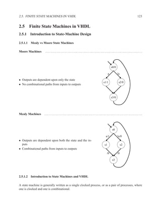
  • 1. 2.5. FINITE STATE MACHINES IN VHDL 123 2.5 Finite State Machines in VHDL 2.5.1 Introduction to State-Machine Design 2.5.1.1 Mealy vs Moore State Machines Moore Machines ..................................................................... . s0/0 a !a • Outputs are dependent upon only the state s1/1 s2/0 • No combinational paths from inputs to outputs s3/0 Mealy Machines . . . . . . . . . . . . . . . . . . . . . . . . . . . . . . . . . . . . . . . . . . . . . . . . . . . . . . . . . . . . . . . . . . . . . .. s0 a/1 !a/0 • Outputs are dependent upon both the state and the in- puts s1 s2 • Combinational paths from inputs to outputs /0 /0 s3 2.5.1.2 Introduction to State Machines and VHDL A state machine is generally written as a single clocked process, or as a pair of processes, where one is clocked and one is combinational.
  • 2. 124 CHAPTER 2. RTL DESIGN WITH VHDL Design Decisions ..................................................................... . • Moore vs Mealy (Sections 2.5.2 and 2.5.3) • Implicit vs Explicit (Section 2.5.1.3) • State values in explicit state machines: Enumerated type vs constants (Section 2.5.5.1) • State values for constants: encoding scheme (binary, gray, one-hot, ...) (Section 2.5.5) VHDL Constructs for State Machines .................................................. The following VHDL control constructs are useful to steer the transition from state to state: • if ... then ... else • loop • case • next • for ... loop • exit • while ... loop 2.5.1.3 Explicit vs Implicit State Machines There are two broad styles of writing state machines in VHDL: explicit and implicit. “Explicit” and “implicit” refer to whether there is an explicit state signal in the VHDL code. Explicit state machines have a state signal in the VHDL code. Implicit state machines do not contain a state signal. Instead, they use VHDL processes with multiple wait statements to control the execution. In the explicit style of writing state machines, each process has at most one wait statement. For the explicit style of writing state machines, there are two sub-categories: “current state” and “cur- rent+next state”. In the explicit-current style of writing state machines, the state signal represents the current state of the machine and the signal is assigned its next value in a clocked process. In the explicit-current+next style, there is a signal for the current state and another signal for the next state. The next-state signal is assigned its value in a combinational process or concurrent state- ment and is dependent upon the current state and the inputs. The current-state signal is assigned its value in a clocked process and is just a flopped copy of the next-state signal. For the implicit style of writing state machines, the synthesis program adds an implicit register to hold the state signal and combinational circuitry to update the state signal. In Synopsys synthesis tools, the state signal defined by the synthesizer is named multiple wait state reg. In Mentor Graphics, the state signal is named STATE VAR We can think of the VHDL code for implicit state machines as having zero state signals, explicit- current state machines as having one state signal (state), and explicit-current+next state ma- chines as having two state signals (state and state next).
  • 3. 2.5.2 Implementing a Simple Moore Machine 125 As with all topics in E&CE 327, there are tradeoffs between these different styles of writing state machines. Most books teach only the explicit-current+next style. This style is the style closest to the hardware, which means that they are more amenable to optimization through human interven- tion, rather than relying on a synthesis tool for optimization. The advantage of the implicit style is that they are concise and readable for control flows consisting of nested loops and branches (e.g. the type of control flow that appears in software). For control flows that have less structure, it can be difficult to write an implicit state machine. Very few books or synthesis manuals describe multiple-wait statement processes, but they are relatively well supported among synthesis tools. Because implicit state machines are written with loops, if-then-elses, cases, etc. it is difficult to write some state machines with complicated control flows in an implicit style. The following example illustrates the point. a s0/0 s2/0 !a !a a s3/0 s1/1 Note: The terminology of “explicit” and “implicit” is somewhat standard, in that some descriptions of processes with multiple wait statements describe the processes as having “implicit state machines”. There is no standard terminology to distinguish between the two explicit styles: explicit-current+next and explicit-current. 2.5.2 Implementing a Simple Moore Machine s0/0 entity simple is a !a port ( a, clk : in std_logic; s1/1 s2/0 z : out std_logic ); end simple; s3/0
  • 4. 126 CHAPTER 2. RTL DESIGN WITH VHDL 2.5.2.1 Implicit Moore State Machine Flops 3 architecture moore_implicit_v1a of simple is Gates 2 begin Delay 1 gate process begin z <= ’0’; wait until rising_edge(clk); if (a = ’1’) then z <= ’1’; else z <= ’0’; end if; wait until rising_edge(clk); z <= ’0’; wait until rising_edge(clk); end process; end moore_implicit; !a s2/0
  • 5. 2.5.2 Implementing a Simple Moore Machine 127 2.5.2.2 Explicit Moore with Flopped Output architecture moore_explicit_v1 of simple is type state_ty is (s0, s1, s2, s3); Flops 3 signal state : state_ty; Gates 10 begin Delay 3 gates process (clk) begin if rising_edge(clk) then case state is when s0 => if (a = ’1’) then state <= s1; z <= ’1’; else state <= s2; z <= ’0’; end if; when s1 | s2 => state <= s3; z <= ’0’; when s3 => state <= s0; z <= ’1’; end case; end if; end process; end moore_explicit_v1;
  • 6. 128 CHAPTER 2. RTL DESIGN WITH VHDL 2.5.2.3 Explicit Moore with Combinational Outputs Flops 2 architecture moore_explicit_v2 of simple is Gates 7 type state_ty is (s0, s1, s2, s3); Delay 4 gates signal state : state_ty; begin process (clk) begin if rising_edge(clk) then case state is when s0 => if (a = ’1’) then state <= s1; else state <= s2; end if; when s1 | s2 => state <= s3; when s3 => state <= s0; end case; end if; end process; z <= ’1’ when (state = s1) else ’0’; end moore_explicit_v2;
  • 7. 2.5.2 Implementing a Simple Moore Machine 129 2.5.2.4 Explicit-Current+Next Moore with Concurrent Assignment Flops 2 architecture moore_explicit_v3 of simple is Gates 7 type state_ty is (s0, s1, s2, s3); Delay 4 signal state, state_nxt : state_ty; begin process (clk) begin if rising_edge(clk) then state <= state_nxt; end if; end process; state_nxt <= s1 when (state = s0) and (a = ’1’) else s2 when (state = s0) and (a = ’0’) else s3 when (state = s1) or (state = s2) else s0; z <= ’1’ when (state = s1) else ’0’; end moore_explicit_v3; The hardware synthesized from this architecture is the same as that synthesized from moore explicit v2, which is written in the current-explicit style.
  • 8. 130 CHAPTER 2. RTL DESIGN WITH VHDL 2.5.2.5 Explicit-Current+Next Moore with Combinational Process architecture moore_explicit_v4 of simple is For this architecture, we type state_ty is (s0, s1, s2, s3); change the selected assign- signal state, state_nxt : state_ty; ment to state into a combi- begin national process using a case process (clk) statement. begin if rising_edge(clk) then Flops 2 state <= state_nxt; Gates 7 end if; Delay 4 end process; process (state, a) The hardware synthe- begin sized from this archi- case state is tecture is the same as when s0 => that synthesized from if (a = ’1’) then moore explicit v2 and state_nxt <= s1; v3. else state_nxt <= s2; end if; when s1 | s2 => state_nxt <= s3; when s3 => state_nxt <= s0; end case; end process; z <= ’1’ when (state = s1) else ’0’; end moore_explicit_v4;
  • 9. 2.5.3 Implementing a Simple Mealy Machine 131 2.5.3 Implementing a Simple Mealy Machine Mealy machines have a combinational path from inputs to outputs, which often violates good coding guidelines for hardware. Thus, Moore machines are much more common. You should know how to write a Mealy machine if needed, but most of the state machines that you design will be Moore machines. This is the same entity as for the simple Moore state machine. The behaviour of the Mealy machine is the same as the Moore machine, except for the timing relationship between the output (z) and the input (a). s0 entity simple is a/1 !a/0 port ( a, clk : in std_logic; s1 s2 z : out std_logic ); /0 /0 end simple; s3
  • 10. 132 CHAPTER 2. RTL DESIGN WITH VHDL 2.5.3.1 Implicit Mealy State Machine Note: An implicit Mealy state machine is nonsensical. In an implicit state machine, we do not have a state signal. But, as the example below illustrates, to create a Mealy state machine we must have a state signal. An implicit style is a nonsensical choice for Mealy state machines. Because the output is depen- dent upon the input in the current clock cycle, the output cannot be a flop. For the output to be combinational and dependent upon both the current state and the current input, we must create a state signal that we can read in the assignment to the output. Creating a state signal obviates the advantages of using an implicit style of state machine. Flops 4 architecture implicit_mealy of simple is Gates 8 type state_ty is (s0, s1, s2, s3); Delay 2 gates signal state : state_ty; begin process begin state <= s0; wait until rising_edge(clk); if (a = ’1’) then state <= s1; else state <= s2; end if; wait until rising_edge(clk); state <= s3; wait until rising_edge(clk); end process; z <= ’1’ when (state = s0) and a = ’1’ else ’0; end mealy_implicit; /0 !a/0 s2
  • 11. 2.5.3 Implementing a Simple Mealy Machine 133 2.5.3.2 Explicit Mealy State Machine Flops 2 architecture mealy_explicit of simple is Gates 7 type state_ty is (s0, s1, s2, s3); Delay 3 signal state : state_ty; begin process (clk) begin if rising_edge(clk) then case state is when s0 => if (a = ’1’) then state <= s1; else state <= s2; end if; when s1 | s2 => state <= s3; when others => state <= s0; end case; end if; end process; z <= ’1’ when (state = s0) and a = ’1’ else ’0’; end mealy_explicit;
  • 12. 134 CHAPTER 2. RTL DESIGN WITH VHDL 2.5.3.3 Explicit-Current+Next Mealy Flops 2 architecture mealy_explicit_v2 of simple is Gates 4 type state_ty is (s0, s1, s2, s3); Delay 3 signal state, state_nxt : state_ty; begin process (clk) begin if rising_edge(clk) then state <= state_nxt; end if; end process; state_nxt <= s1 when (state = s0) and a = ’1’ else s2 when (state = s0) and a = ’0’ else s3 when (state = s1) or (state = s2) else s0; z <= ’1’ when (state = s0) and a = ’1’ else ’0’; end mealy_explicit_v2; For the Mealy machine, the explicit-current+next style is smaller than the the explicit-current style. In contrast, for the Moore machine, the two styles produce exactly the same hardware.
  • 13. 2.5.4 Reset 135 2.5.4 Reset All circuits should have a reset signal that puts the circuit back into a good initial state. However, not all flip flops within the circuit need to be reset. In a circuit that has a datapath and a state machine, the state machine will probably need to be reset, but datapath may not need to be reset. There are standard ways to add a reset signal to both explicit and implicit state machines. It is important that reset is tested on every clock cycle, otherwise a reset might not be noticed, or your circuit will be slow to react to reset and could generate illegal outputs after reset is asserted. Reset with Implicit State Machine . . .. . . . . .. . . . . .. . . . . .. . . . . .. . . . . .. . . . . .. . . . . . .. . . . . ... With an implicit state machine, we need to insert a loop in the process and test for reset after each wait statement. Here is the implicit Moore machine from section 2.5.2.1 with reset code added in bold. architecture moore_implicit of simple is begin process begin init : loop -- outermost loop z <= ’0’; wait until rising_edge(clk); next init when (reset = ’1’); -- test for reset if (a = ’1’) then z <= ’1’; else z <= ’0’; end if; wait until rising_edge(clk); next init when (reset = ’1’); -- test for reset z <= ’0’; wait until rising_edge(clk); next init when (reset = ’1’); -- test for reset end process; end moore_implicit;
  • 14. 136 CHAPTER 2. RTL DESIGN WITH VHDL Reset with Explicit State Machine ...................................................... Reset is often easier to include in an explicit state machine, because we need only put a test for reset = ’1’ in the clocked process for the state. The pattern for an explicit-current style of machine is: process (clk) begin if rising_edge(clk) then if reset = ’1’ then state <= S0; else if ... then state <= ...; elif ... then ... -- more tests and assignments to state end if; end if; end if; end process; Applying this pattern to the explicit Moore machine from section 2.5.2.3 produces: architecture moore_explicit_v2 of simple is type state_ty is (s0, s1, s2, s3); signal state : state_ty; begin process (clk) begin if rising_edge(clk) then if (reset = ’1’) then state <= s0; else case state is when s0 => if (a = ’1’) then state <= s1; else state <= s2; end if; when s1 | s2 => state <= s3; when s3 => state <= s0; end case; end if; end if; end process; z <= ’1’ when (state = s1) else ’0’; end moore_explicit_v2;
  • 15. 2.5.5 State Encoding 137 The pattern for an explicit-current+next style is: process (clk) begin if rising_edge(clk) then if reset = ’1’ then state_cur <= reset state; else state_cur <= state_nxt; end if; end if; end process; 2.5.5 State Encoding When working with explicit state machines, we must address the issue of state encoding: what bit-vector value to associate with each state? With implicit state machines, we do not need to worry about state encoding. The synthesis program determines the number of states and the encoding for each state. 2.5.5.1 Constants vs Enumerated Type Using an enumerated type, the synthesis tools chooses the encoding: type state_ty is (s0, s1, s2, s3); signal state : state_ty; Using constants, we choose the encoding: type state_ty is std_logic_vector(1 downto 0); constant s0 : state_ty := "11"; constant s1 : state_ty := "10"; constant s2 : state_ty := "00"; constant s3 : state_ty := "01"; signal state : state_ty; Providing Encodings for Enumerated Types ............................................ Many synthesizers allow the user to provide hints on how to encode the states, or allow the user to provide explicitly the desire encoding. These hints are done either through VHDL attributes or special comments in the code.
  • 16. 138 CHAPTER 2. RTL DESIGN WITH VHDL Simulation ............................................................................ When doing functional simulation with enumerated types, simulators often display waveforms with “pretty-printed” values rather than bits (e.g. s0 and s1 rather than 11 and 10). However, when simulating a design that has been mapped to gates, the enumerated type dissappears and you are left with just bits. If you don’t know the encoding that the synthesis tool chose, it can be very difficult to debug the design. However, this opens you up to potential bugs if the enumerated type you are testing grows to include more values, which then end up unintentionally executing your when other branch, rather than having a special branch of their own in the case statement. Unused Values ....................................................................... . If the number of values you have in your datatype is not a power of two, then you will have some unused values that are representable. For example: type state_ty is std_logic_vector(2 downto 0); constant s0 : state_ty := "011"; constant s1 : state_ty := "000"; constant s2 : state_ty := "001"; constant s3 : state_ty := "011"; constant s4 : state_ty := "101"; signal state : state_ty; This type only needs five unique values, but can represent eight different values. What should we do with the three representable values that we don’t need? The safest thing to do is to code your design so that if an illegal value is encountered, the machine resets or enters an error state. 2.5.5.2 Encoding Schemes • Binary: Conventional binary counter. • One-hot: Exactly one bit is asserted at any time. • Modified one-hot: Altera’s Quartus synthesizer generates an almost-one-hot encoding where the bit representing the reset state is inverted. This means that the reset state is all ’O’s and all other states have two ’1’s: one for the reset state and one for the current state. • Gray: Transition between adjacent values requires exactly one bit flip. • Custom: Choose encoding to simplify combinational logic for specific task.
  • 17. 2.6. DATAFLOW DIAGRAMS 139 Tradeoffs in Encoding Schemes ....................................................... . • Gray is good for low-power applications where consecutive data values typically differ by 1 (e.g. no random jumps). • One-hot usually has less combinational logic and runs faster than binary for machines with up to a dozen or so states. With more than a dozen states, the extra flip-flops required by one-hot encoding become too expensive. • Custom is great if you have lots of time and are incredibly intelligent, or have deep insight into the guts of your design. Note: Don’t care values When we don’t care what is the value of a signal we assign the signal ’-’, which is “don’t care” in VHDL. This should allow the synthesis tool to use whatever value is most helpful in simplifying the Boolean equations for the signal (e.g. Karnaugh maps). In the past, some groups in E&CE 327 have used ’-’ quite succesfuly to decrease the area of their design. However, a few groups found that using ’-’ increased the size of their design, when they were expecting it to decrease the size. So, if you are tweaking your design to squeeze out the last few unneeded FPGA cells, pay close attention as to whether using ’-’ hurts or helps. 2.6 Dataflow Diagrams 2.6.1 Dataflow Diagrams Overview • Dataflow diagrams are data-dependency graphs where the computation is divided into clock cycles. • Purpose: – Provide a disciplined approach for designing datapath-centric circuits – Guide the design from algorithm, through high-level models, and finally to register transfer level code for the datapath and control circuitry. – Estimate area and performance – Make tradeoffs between different design options • Background – Based on techniques from high-level synthesis tools – Some similarity between high-level synthesis and software compilation – Each dataflow diagram corresponds to a basic block in software compiler terminology.