SlideShare ist ein Scribd-Unternehmen logo
1 von 42
©Dr. Anwar Siddiqui
Physiology Seminar
15/01/2013
ELECTROCARDIOGRAPHY
PRACTICAL PHYSIOLOGY
1
2
INTRODUCTION
 ECG is a three letter acronym for ElectroCardioGraphy.
 The word is derived from electro(greek for
electricity),cardio(greek for heart) and graph(Greek root
meaning "to write“)
 It is a transthoracic interpretation of the electrical activity
of the heart over time captured and externally recorded
by skin electrodes.
 The device used to produce this non invasive record is
called the electrocardiograph.
 ECG is the gold standard for the noninvasive diagnosis of
cardiac diseases and may occasionally be the only marker
for the presence of heart disease.
INDICATIONS OF ECG
 Gold standard for diagnosis of cardiac arrhythmias
 Helps detect electrolyte disturbances (hyper- &
hypokalemia)
 Allows for detection of conduction abnormalities
 Screening tool for ischemic heart disease during stress
tests
 Helpful with non-cardiac diseases (e.g. pulmonary
embolism or hypothermia
An ECG is a diagnostic tool, NOT a treatment
No one is ever cured by an ECG!!
3
4
ELECTROCARDIOGRAPHY TIMELINE
 1872:Alexander Muirhead attached wires to a feverish
patient's wrist to obtain a record of the patient's heartbeat
St Bartholomew's Hospital.
 1887:British physiologist Augustus D. Waller of St Mary's
Medical School, London publishes the first human
electrocardiogram. The trace from the heartbeat was
projected onto a photographic plate which was itself fixed
to a toy train
 1893:Dutch physiologist Willem Einthoven introduces the
term 'electrocardiogram' at a meeting of the Dutch Medical
Association.
 1895: Willem Einthoven distinguishes five deflections
which he names P
, Q, R, S and T
5
1902: Einthoven publishes the first electro -
cardiogram recorded on a string galvanometer.
1912: Einthoven addresses the Chelsea Clinical
Society in London and describes an equilateral
triangle formed by his standard leads I, II and III
later called 'Einthoven's triangle'.
1924: Willem Einthoven wins the Nobel prize for
inventing the electrocardiograph.
• Figure depicting Einthoven recording his first ECG
in 1902 by placing limbs in buckets of conducting
solution!
6
7
BASIC ELECTROPHYSIOLOGY
PHYSIOLOGICAL PROPERTIES OF MYOCARDIAL CELL
Automaticity: ability to initiate an impulse
Excitability: ability to respond to a stimulus
Conductivity: ability to transmit an impulse
Contractility: ability to respond with pumping
action
Depolarization and repolarization of a cardiac cell
generates action potential
ECG is the composite representation of action
potential of all cardiac cell.
8
ELECTRICAL CONDUCTION SYSTEM OF THE HEART
 The electrical discharge for each cardiac cycle normally
starts in a special area of the right atrium called the
‘sinoatrial (SA) node’.
 Depolarization then spreads through the atrial muscle
fibres.
 There is a delay while the depolarization spreads through
another special area in the atrium, the ‘atrioventricular
(AV) node’.
 Thereafter, the electrical discharge travels very rapidly,
down specialized conduction tissue: first a single
pathway, the ‘bundle of His’, which then divides in the
septum between the ventricles into right and left bundle
branches.
 Within the ventricular mass, conduction spreads somewhat
moreslowly, through specialized tissue called ‘Purkinje
fibres’.
9
10
Conduction speed of cardiac tissue
TISSUE CONDUCTION
RATE (m/s)
SA node 0.05
Atrial pathway 1
AV node 0.05
Bundle of His 0.05
Purkinje system 4
Ventricular muscle 1
11
CONDUCTION OF THE IMPULSE:
Normal resting membrane potential=-90mv
If the potential rises from -90 to 0, then this excites a
further rise of potential, called the action potential.
The action potential is transmitted throughout the
cell and forms the impulse.
During the rise of potential, the membrane becomes
permeable to Sodium ions and the potential rises to a
positive direction. This phenomena is called
depolarization.
The Sodium channels close and there is rapid
diffusion of K+ ions into the exterior, reestablishing
the resting membrane potential. This is called
 Depolarization is followed by muscle contraction and
repolarisation is followed by muscle relaxation.
• Fig depicting the mechanism of depolarisation and
repolarisation
Depol Repol
12
Restoration of ionic
balance
NORMAL SINUS RYTHEM
The adjacent figure shows the normal sinus rythem
A normal sinus rythem comprises of the following
waves:-
•P waves- denotes atrial depolarization(electrical
vector is directed from the SA node towards the AV
node)
• QRS complex- denotes depolarization of ventricles as
well as repolization of atrium
•T waves- denotes the repolarization (or recovery) of
the ventricles. The interval from the beginning of the
QRS complex to the apex of the T wave is referred to as
the absolute refractory period. The last half of the T
wave is referred to as the relative refractory period.
As depicted in the fig:-
•PR interval- beginning of the P wave to the beginning
of the QRS complex
•ST segment- connects the QRS complex and the T
wave.
•QT interval- the beginning of the QRS complex to the
end of the T wave.
13
What differentiates a segment from an interval?
 A segment is a straight line connecting two waves.
 An interval encompasses at least one wave plus the
connecting straight line.
14
15
 J point- J-point is the point at which the QRS complex meets the ST wave.
 Its an isoelectric point and its importance lies in the fact that ST segment
elevation is measured with respect to it
 J WAVE AND U WAVE:These are two abnormal waves that may be seen
sumtime in the ecg recordings.
o J wave
• also known as camel-hump sign, late delta wave, hathook junction, hypothermic
wave, prominent J wave ,[1] K wave, H wave or current of injury
• positive deflections occurring at the junction between the QRS complex and ST
segment(j point)
• observed in people suffering from hypothermia with a temperature of less than
32
o U wave
• typically small, and, by definition, follows the T wave
• Prominent U waves are most often seen in hypokalemia, but may be present
in hypercalcemia, thyrotoxicosis
Fig representing the J point
Fig representing the J wave in an
hypothermic individual
The arrow in the figure represents
the U wave in a hypokalemic
patient
16
17
RECORDING THE ELECTROCARDIOGRAM
THE E.C.G PAPER
 ECG machines record changes in electrical activity by
drawing a trace on a moving paper strip.
 The electrocardiograph uses thermal paper, which is a
graph paper & runs normally at a speed of 25mm/sec
 Time is plotted on the X axis & voltage is plotted on the Y
axis.
 In X axis, 1 second is divided into 5 large squares each of
which represents 0.2 sec. Each large square is further
divided into 5 small squares which represents 0.04 sec.
 The ECG machine is calibrated in such a way that an
increase of voltage by 1 mVolt should move the stylus
vertically by 1cms.
ECG PAPER
• Fig adjacent shows a callibration
graph.By callibration we mean that an
increase of voltage by 1mVolt should
move the stylus vertically by 1cms. . The
calibration signal should be included
with every record
18
19
ELECTROCARDIOGRAPHIC LEADS - CONVENTIONAL
 12 conventional leads, physiologically divided into two groups
viz:
Bipolar leads- 3 Standard limb leads
Unipolar leads-3 Augmented limb leads and 6 precordial
chest leads
 Bipolar leads : These record the actual difference in potential
across the two electrodes. There are three standard limb
lead:-
• Lead I Left arm Right arm
• Lead II Left foot Right arm
• Lead III Left foot Left arm
o The lead axes form the sides of an equilateral triangle with
the heart at the center ( Einthoven's triangle)
20
o The sum total of the potential in the three leads equals zero
and mathematically it co uld be demonstrated that the
potential in L II equals sum of the potentials in L I and L III i.e,
Einthoven's law.
 Unipolar limb leads:
• Constituted by the indifferent electrode which forms the
negative electrode and the exploring electrode which forms
the positive electrode.
• The indifferent electrode is constituted by connecting all limb
lead electrodes together through an electrical resistance
there by maintaining the zero potential. The positive
electrode records the true potential at a given point. Here the
record is of low voltage.
• Goldberger augmented these leads for proper
recording,came to be known as augmented unipolar limb
leads, represented by aVR, aVF, aVL leads
According to Kirchhoff's law these lead voltages have the following relationship:
VI + VIII = VII
21
 Unipolar chest leads
 Constituted by an indifferent electrode resulting from a
connection between all three standard limb leads and an
exploring electrode placed on 6 different points on the
chest wall.
 The indifferent electrode forms the negative terminal
&the exploring electrode forms the positive terminal.
 Placement of precordial leads.
V 1 - 4th intercostal space , right of sternum.
V 2 - 4th ICS left of sternum
V 4 - 5th ICS midclavicular line
V 3 - Midway between V2 and V4
V 5 - 5th ICS anterior axillary line.
V 6 - 5th ICS mid axillary line. 22
Diagram depicting the einthoven’s
Triangle along with the position of
various electrodes used in the ECG
Legend:
RA-right arm
LA-left arm
L leg-left leg
V1 to V6-precordial chest lead
aVR-augmented vector right arm
aVL-augmented vector left arm
aVF-augmented vector left foot
23
 Leads I, II and aVL look at the left lateral surface of the heart
 leads III and aVF at the inferior surface, and lead aVR looks at the
right atrium
 The V leads are attached to the chest wall by means of a
suction electrode
• leads V1 and V2 look at the right ventricle
• V3 and V4 look at the septum between the ventricles and the
anterior wall of the left ventricle
• V5 and V6 look at the anterior and lateral walls of the left ventricle
24
• An overview of the electrocardiographic leads
25
26
MAKING A RECORDING
 Good contact between body surface and electrode is necessary. It
might be essential to shave the chest and apply electro cardio
graphic jelly
 The patient must lie down and relax to prevent muscle tremor
 Connect up the limb electrodes to the correct limb.limb electrodes
have marking on them and also they are colour coded(red –right
arm,yellow-left arm,gren left leg and black-right leg)
 Calibrate the record with 1mv signal.There shouldn’t be
overdamping or underdamping.
 Any metallic object like watch or jwelleary should be removef from
the patients body
 4-5 recording of each lead is recorded
27
FUNDAMENTAL PRINCIPLES BEHIND THE RECORDING
 An electromagnetic force, current or vector has both
magnitude and direction. When this force is directed to
the positive electrode of a lead, the ECG will record an
upward or positive deflection
 When the vector is directed away from the positive
electrode the ECG will record a downward or negative
deflection, if at 90degree to the electrode the wave
touches the baseline
 physiologically, left ventricle and inter ventricular septum
constitutes the dominant part,and hence maximally
influences variations in ECG.
WAVES FORMATION
A wave of depolarisation moving away from the elec trode causes negative deflewctio2n8
A wave of depolarisation moving toward a positive electrode records a positive deflection
• EKG recording if the positive electrode is placed
in the middle of the cell
29
 We can easily apply these concepts to the entire heart.
 Electrodes placed on the surface of the body will record
waves of depolarization and repolarization as they sweep
through the heart.
30
31
HOW TO REPRT AN ECG
 Ecg strip should be correctly labelled(the patients particular and
all the lead markings)
 The ecg recording should be described under the following heads:
• Heart rate
• Rythem
• Various conduction intervals (pr interval ,qt interval)
• Description of QRS complex ,ST segment and T waves
• Cardiac axis
• Any abnormal wave like J and U waves
 Heart rate:calculated by dividing 1500 by number of small box
between two consecutive R waves
• Sinus tachycardia-heart rate more than 100 beats per minute.
• Sinus bradycardia-heart rate less than 60 beats per minute
32
 Rhythm- rhythm controlled by sinus node at a rate of 60-100
beats/min; each P wave followed by QRS and each QRS preceded
by a P wave.
Specific Arrhythmias
• Sinus bradycardia
• Sinus tachycardia
• Sick sinus syndrome- disturbance of SA nodal function that results
in a markedly variable rhythm (cycles of bradycardia and
tachycardia).
• Atrial flutter - sinus rate of 250-350 beats/min
• AV nodal blocks - a conduction block within the AV node (or
occasionally in the bundle of His) that impairs impulse conduction
from the atria to the ventricles.
• Ventricular flutter - very rapid ventricular depolarizations >250/min
• Ventricular fibrillation - uncoordinated ventricular depolarizations;
leads to death if not quickly corrected
NORMAL SINUS RHYTHM Impulses originate at S-A node at normal rate
33
SINUS TACHYCARDIA Impulses originate at S-A node at rapid rate
ATRIAL FLUTTER Impulses travel in circular course in atria – No interval between T and P
ATRIAL FIBRILLATION Impluses have chaotic, random pathways in atria
34
VENTRICULAR TACHYCARDIA
Impulse originate at ventricular pacemaker – odd/wide QRS complex
VENTRICULAR FIBRILLATION
Chaotic ventricular depolarization – ineffective at pumping blood – death within minutes
A-V BLOCK, FIRST DEGREE Atrio-ventricular conduction lengthened
P-wave precedes each QRS-complex but PR-interval is > 0.2 s
35
A-V BLOCK, SECOND DEGREE Sudden dropped QRS-complex
Intermittently skipped ventricular beat
36
 PR interval and QT interval
• The PR interval extends from the start of the P wave to the
very start of the QRS complex.
• A normal value is 0.12 to 0.20 seconds
• Its significance lies in assessing the nodal blocks
• QT interval is a measure of the time between the start of the Q
wave and the end of the T wave
• Normal values for the QT interval are between 0.30 and 0.44 secs
• If abnormally prolonged or shortened, there is a risk of developing
ventricular arrythmias
 QRS complex and ST segment
• The QRS complex is 0.08 to 0.12 sec
• Not every QRS complex contains a Q wave, an R wave, and an S wave
• The duration, amplitude, and morphology of the QRS complex is useful in
diagnosing, arrythmias, conduction abnormality, myocardialinfarction,
and other disease states.
37
• ST segment connects theQRS complex and theT wave and has a duration of
0.08 to 0.12 sec
• ST segment elevation or depression is associated with various cardiac
abnormality
Conditions causing ST segment elevation
Acute myocardial infarction
Pericarditis
Left Ventricular Hypertrophy
Left Bundle Branch Block
hyperkalemia
Conditions causing ST segment depression
Ischemic heart disease
Hypokalemia
Secondary ST segment changes with conduction abnormalities (e.g., RBBB,
LBBB, WPW, etc
hypokalemia
Morphology of ST segment elevation
 AMI usually demonstrate straight/convex STE
 Concave shaped STE-non AMI causes
38
39
 Cardiac axis
• The electrical axis of the heart is the mean direction of the action
potentials traveling through the ventricles during ventricular
activation (depolarization)
• The QRS complex, which represents ventricular depolarization, is
used for the determination of the electrical heart axis.
• The normal electrical axis of the heart is situated between -30
degrees and +90 degrees (positive 90 degrees) with respect to the
horizontal line
• Left axis deviation: the electrical heart axis is between -30 degrees
and -90 degrees with respect to the horizontal line.
• Right axis deviation: the electrical heart axis is between +90
degrees and 180 degrees with respect to the horizontal line.
• Extreme axis deviation (also known as northwest axis or no man’s
land): the electrical heart axis is between +180 degrees and -90
degrees with respect to the horizontal line.
Fig showing the cardiac axis in hexaxial referrance system
causes of right axis deviation
•normal finding in children and tall thin adults
•right ventricular hypertrophy
•chronic lung
•anterolateral myocardial infarction
•left posterior hemiblock
•Wolff-Parkinson-White syndrome - left sided accessory pathway
•atrial septal defect
•ventricular septal defect 40
41
causes of left axis deviation
• left anterior hemiblock
• Q waves of inferior myocardial infarction
• emphysema
• hyperkalaemia
• Wolff-Parkinson-White syndrome - right sided accessory pathway
• tricuspid atresia
• ostium primum ASD
• injection of contrast into left coronary artery
causes of a Northwest axis (no man's land)
• emphysema
• hyperkalaemia
• lead transposition
• artificial cardiac pacing
• ventricular tachycardia
REFERENCES
• Only EKG Book You'll Ever Need, Thaler, Malcom S, 2007 Lippincott
Williams & Wilkins 5th Edition
• Schamroth L. Electrical axis. In : Schamroth C. (ed)An introduction
to Electrocardiography, Blackwell Science Ltd. Massachusetts 1990;
34–48.
• John.R.Hampton the ECG made easy 6th edition ,Churchill
Livingstone publication
theend… .. thank you
42

Weitere ähnliche Inhalte

Ähnlich wie ECG(Electrocardiogram) presentation

30. cardiovascular 2-07-08
30. cardiovascular 2-07-0830. cardiovascular 2-07-08
30. cardiovascular 2-07-08Nasir Koko
 
Electrocardiogram (ECG) / ECG interpretation
Electrocardiogram (ECG) / ECG interpretationElectrocardiogram (ECG) / ECG interpretation
Electrocardiogram (ECG) / ECG interpretationRahul Jaga
 
BASICS OF ECG pptx.pptx
BASICS OF ECG pptx.pptxBASICS OF ECG pptx.pptx
BASICS OF ECG pptx.pptxsandhiyaraja5
 
Fundamentals of Electrocardiography
Fundamentals of Electrocardiography Fundamentals of Electrocardiography
Fundamentals of Electrocardiography Saran A K
 
Ppt recording on ecocardiogram
Ppt recording on ecocardiogramPpt recording on ecocardiogram
Ppt recording on ecocardiogramRekha kumari
 
ECG interpretation: Echocardiography and Cardiac Catherization.pptx
ECG interpretation: Echocardiography and Cardiac Catherization.pptxECG interpretation: Echocardiography and Cardiac Catherization.pptx
ECG interpretation: Echocardiography and Cardiac Catherization.pptxprincessezepeace
 
Electrocardiography (ecg)
Electrocardiography (ecg)Electrocardiography (ecg)
Electrocardiography (ecg)Madah Khan
 
Introduction to ECG
Introduction to ECGIntroduction to ECG
Introduction to ECGdelkol
 
ecg-130715033518-phpapp02-1.pdf
ecg-130715033518-phpapp02-1.pdfecg-130715033518-phpapp02-1.pdf
ecg-130715033518-phpapp02-1.pdfAtiqurRahman7153
 

Ähnlich wie ECG(Electrocardiogram) presentation (20)

30. cardiovascular 2-07-08
30. cardiovascular 2-07-0830. cardiovascular 2-07-08
30. cardiovascular 2-07-08
 
ECG
ECGECG
ECG
 
Electrocardiogram (ECG) / ECG interpretation
Electrocardiogram (ECG) / ECG interpretationElectrocardiogram (ECG) / ECG interpretation
Electrocardiogram (ECG) / ECG interpretation
 
BASICS OF ECG pptx.pptx
BASICS OF ECG pptx.pptxBASICS OF ECG pptx.pptx
BASICS OF ECG pptx.pptx
 
Fundamentals of Electrocardiography
Fundamentals of Electrocardiography Fundamentals of Electrocardiography
Fundamentals of Electrocardiography
 
BASICS IN ECG.pptx
BASICS IN ECG.pptxBASICS IN ECG.pptx
BASICS IN ECG.pptx
 
Ecg part i
Ecg part iEcg part i
Ecg part i
 
Ppt recording on ecocardiogram
Ppt recording on ecocardiogramPpt recording on ecocardiogram
Ppt recording on ecocardiogram
 
Ecg
EcgEcg
Ecg
 
ECG interpretation: Echocardiography and Cardiac Catherization.pptx
ECG interpretation: Echocardiography and Cardiac Catherization.pptxECG interpretation: Echocardiography and Cardiac Catherization.pptx
ECG interpretation: Echocardiography and Cardiac Catherization.pptx
 
Electrocardiography (ecg)
Electrocardiography (ecg)Electrocardiography (ecg)
Electrocardiography (ecg)
 
ecg.pptx
ecg.pptxecg.pptx
ecg.pptx
 
ECG.ppt
ECG.pptECG.ppt
ECG.ppt
 
Introduction to ECG
Introduction to ECGIntroduction to ECG
Introduction to ECG
 
ECG1.pptx
ECG1.pptxECG1.pptx
ECG1.pptx
 
ECG by Adil.pptx
ECG by Adil.pptxECG by Adil.pptx
ECG by Adil.pptx
 
Electrocardiogram
Electrocardiogram Electrocardiogram
Electrocardiogram
 
1.3.1.8 - Dasar-Dasar EKG.pdf
1.3.1.8 - Dasar-Dasar EKG.pdf1.3.1.8 - Dasar-Dasar EKG.pdf
1.3.1.8 - Dasar-Dasar EKG.pdf
 
CVS-2.pptx
CVS-2.pptxCVS-2.pptx
CVS-2.pptx
 
ecg-130715033518-phpapp02-1.pdf
ecg-130715033518-phpapp02-1.pdfecg-130715033518-phpapp02-1.pdf
ecg-130715033518-phpapp02-1.pdf
 

Kürzlich hochgeladen

Activity 2-unit 2-update 2024. English translation
Activity 2-unit 2-update 2024. English translationActivity 2-unit 2-update 2024. English translation
Activity 2-unit 2-update 2024. English translationRosabel UA
 
Incoming and Outgoing Shipments in 3 STEPS Using Odoo 17
Incoming and Outgoing Shipments in 3 STEPS Using Odoo 17Incoming and Outgoing Shipments in 3 STEPS Using Odoo 17
Incoming and Outgoing Shipments in 3 STEPS Using Odoo 17Celine George
 
Earth Day Presentation wow hello nice great
Earth Day Presentation wow hello nice greatEarth Day Presentation wow hello nice great
Earth Day Presentation wow hello nice greatYousafMalik24
 
ENG 5 Q4 WEEk 1 DAY 1 Restate sentences heard in one’s own words. Use appropr...
ENG 5 Q4 WEEk 1 DAY 1 Restate sentences heard in one’s own words. Use appropr...ENG 5 Q4 WEEk 1 DAY 1 Restate sentences heard in one’s own words. Use appropr...
ENG 5 Q4 WEEk 1 DAY 1 Restate sentences heard in one’s own words. Use appropr...JojoEDelaCruz
 
Karra SKD Conference Presentation Revised.pptx
Karra SKD Conference Presentation Revised.pptxKarra SKD Conference Presentation Revised.pptx
Karra SKD Conference Presentation Revised.pptxAshokKarra1
 
MULTIDISCIPLINRY NATURE OF THE ENVIRONMENTAL STUDIES.pptx
MULTIDISCIPLINRY NATURE OF THE ENVIRONMENTAL STUDIES.pptxMULTIDISCIPLINRY NATURE OF THE ENVIRONMENTAL STUDIES.pptx
MULTIDISCIPLINRY NATURE OF THE ENVIRONMENTAL STUDIES.pptxAnupkumar Sharma
 
Choosing the Right CBSE School A Comprehensive Guide for Parents
Choosing the Right CBSE School A Comprehensive Guide for ParentsChoosing the Right CBSE School A Comprehensive Guide for Parents
Choosing the Right CBSE School A Comprehensive Guide for Parentsnavabharathschool99
 
Transaction Management in Database Management System
Transaction Management in Database Management SystemTransaction Management in Database Management System
Transaction Management in Database Management SystemChristalin Nelson
 
Field Attribute Index Feature in Odoo 17
Field Attribute Index Feature in Odoo 17Field Attribute Index Feature in Odoo 17
Field Attribute Index Feature in Odoo 17Celine George
 
USPS® Forced Meter Migration - How to Know if Your Postage Meter Will Soon be...
USPS® Forced Meter Migration - How to Know if Your Postage Meter Will Soon be...USPS® Forced Meter Migration - How to Know if Your Postage Meter Will Soon be...
USPS® Forced Meter Migration - How to Know if Your Postage Meter Will Soon be...Postal Advocate Inc.
 
4.16.24 Poverty and Precarity--Desmond.pptx
4.16.24 Poverty and Precarity--Desmond.pptx4.16.24 Poverty and Precarity--Desmond.pptx
4.16.24 Poverty and Precarity--Desmond.pptxmary850239
 
ISYU TUNGKOL SA SEKSWLADIDA (ISSUE ABOUT SEXUALITY
ISYU TUNGKOL SA SEKSWLADIDA (ISSUE ABOUT SEXUALITYISYU TUNGKOL SA SEKSWLADIDA (ISSUE ABOUT SEXUALITY
ISYU TUNGKOL SA SEKSWLADIDA (ISSUE ABOUT SEXUALITYKayeClaireEstoconing
 
Influencing policy (training slides from Fast Track Impact)
Influencing policy (training slides from Fast Track Impact)Influencing policy (training slides from Fast Track Impact)
Influencing policy (training slides from Fast Track Impact)Mark Reed
 
ANG SEKTOR NG agrikultura.pptx QUARTER 4
ANG SEKTOR NG agrikultura.pptx QUARTER 4ANG SEKTOR NG agrikultura.pptx QUARTER 4
ANG SEKTOR NG agrikultura.pptx QUARTER 4MiaBumagat1
 
4.18.24 Movement Legacies, Reflection, and Review.pptx
4.18.24 Movement Legacies, Reflection, and Review.pptx4.18.24 Movement Legacies, Reflection, and Review.pptx
4.18.24 Movement Legacies, Reflection, and Review.pptxmary850239
 
How to Add Barcode on PDF Report in Odoo 17
How to Add Barcode on PDF Report in Odoo 17How to Add Barcode on PDF Report in Odoo 17
How to Add Barcode on PDF Report in Odoo 17Celine George
 
Difference Between Search & Browse Methods in Odoo 17
Difference Between Search & Browse Methods in Odoo 17Difference Between Search & Browse Methods in Odoo 17
Difference Between Search & Browse Methods in Odoo 17Celine George
 
Concurrency Control in Database Management system
Concurrency Control in Database Management systemConcurrency Control in Database Management system
Concurrency Control in Database Management systemChristalin Nelson
 
Inclusivity Essentials_ Creating Accessible Websites for Nonprofits .pdf
Inclusivity Essentials_ Creating Accessible Websites for Nonprofits .pdfInclusivity Essentials_ Creating Accessible Websites for Nonprofits .pdf
Inclusivity Essentials_ Creating Accessible Websites for Nonprofits .pdfTechSoup
 
Daily Lesson Plan in Mathematics Quarter 4
Daily Lesson Plan in Mathematics Quarter 4Daily Lesson Plan in Mathematics Quarter 4
Daily Lesson Plan in Mathematics Quarter 4JOYLYNSAMANIEGO
 

Kürzlich hochgeladen (20)

Activity 2-unit 2-update 2024. English translation
Activity 2-unit 2-update 2024. English translationActivity 2-unit 2-update 2024. English translation
Activity 2-unit 2-update 2024. English translation
 
Incoming and Outgoing Shipments in 3 STEPS Using Odoo 17
Incoming and Outgoing Shipments in 3 STEPS Using Odoo 17Incoming and Outgoing Shipments in 3 STEPS Using Odoo 17
Incoming and Outgoing Shipments in 3 STEPS Using Odoo 17
 
Earth Day Presentation wow hello nice great
Earth Day Presentation wow hello nice greatEarth Day Presentation wow hello nice great
Earth Day Presentation wow hello nice great
 
ENG 5 Q4 WEEk 1 DAY 1 Restate sentences heard in one’s own words. Use appropr...
ENG 5 Q4 WEEk 1 DAY 1 Restate sentences heard in one’s own words. Use appropr...ENG 5 Q4 WEEk 1 DAY 1 Restate sentences heard in one’s own words. Use appropr...
ENG 5 Q4 WEEk 1 DAY 1 Restate sentences heard in one’s own words. Use appropr...
 
Karra SKD Conference Presentation Revised.pptx
Karra SKD Conference Presentation Revised.pptxKarra SKD Conference Presentation Revised.pptx
Karra SKD Conference Presentation Revised.pptx
 
MULTIDISCIPLINRY NATURE OF THE ENVIRONMENTAL STUDIES.pptx
MULTIDISCIPLINRY NATURE OF THE ENVIRONMENTAL STUDIES.pptxMULTIDISCIPLINRY NATURE OF THE ENVIRONMENTAL STUDIES.pptx
MULTIDISCIPLINRY NATURE OF THE ENVIRONMENTAL STUDIES.pptx
 
Choosing the Right CBSE School A Comprehensive Guide for Parents
Choosing the Right CBSE School A Comprehensive Guide for ParentsChoosing the Right CBSE School A Comprehensive Guide for Parents
Choosing the Right CBSE School A Comprehensive Guide for Parents
 
Transaction Management in Database Management System
Transaction Management in Database Management SystemTransaction Management in Database Management System
Transaction Management in Database Management System
 
Field Attribute Index Feature in Odoo 17
Field Attribute Index Feature in Odoo 17Field Attribute Index Feature in Odoo 17
Field Attribute Index Feature in Odoo 17
 
USPS® Forced Meter Migration - How to Know if Your Postage Meter Will Soon be...
USPS® Forced Meter Migration - How to Know if Your Postage Meter Will Soon be...USPS® Forced Meter Migration - How to Know if Your Postage Meter Will Soon be...
USPS® Forced Meter Migration - How to Know if Your Postage Meter Will Soon be...
 
4.16.24 Poverty and Precarity--Desmond.pptx
4.16.24 Poverty and Precarity--Desmond.pptx4.16.24 Poverty and Precarity--Desmond.pptx
4.16.24 Poverty and Precarity--Desmond.pptx
 
ISYU TUNGKOL SA SEKSWLADIDA (ISSUE ABOUT SEXUALITY
ISYU TUNGKOL SA SEKSWLADIDA (ISSUE ABOUT SEXUALITYISYU TUNGKOL SA SEKSWLADIDA (ISSUE ABOUT SEXUALITY
ISYU TUNGKOL SA SEKSWLADIDA (ISSUE ABOUT SEXUALITY
 
Influencing policy (training slides from Fast Track Impact)
Influencing policy (training slides from Fast Track Impact)Influencing policy (training slides from Fast Track Impact)
Influencing policy (training slides from Fast Track Impact)
 
ANG SEKTOR NG agrikultura.pptx QUARTER 4
ANG SEKTOR NG agrikultura.pptx QUARTER 4ANG SEKTOR NG agrikultura.pptx QUARTER 4
ANG SEKTOR NG agrikultura.pptx QUARTER 4
 
4.18.24 Movement Legacies, Reflection, and Review.pptx
4.18.24 Movement Legacies, Reflection, and Review.pptx4.18.24 Movement Legacies, Reflection, and Review.pptx
4.18.24 Movement Legacies, Reflection, and Review.pptx
 
How to Add Barcode on PDF Report in Odoo 17
How to Add Barcode on PDF Report in Odoo 17How to Add Barcode on PDF Report in Odoo 17
How to Add Barcode on PDF Report in Odoo 17
 
Difference Between Search & Browse Methods in Odoo 17
Difference Between Search & Browse Methods in Odoo 17Difference Between Search & Browse Methods in Odoo 17
Difference Between Search & Browse Methods in Odoo 17
 
Concurrency Control in Database Management system
Concurrency Control in Database Management systemConcurrency Control in Database Management system
Concurrency Control in Database Management system
 
Inclusivity Essentials_ Creating Accessible Websites for Nonprofits .pdf
Inclusivity Essentials_ Creating Accessible Websites for Nonprofits .pdfInclusivity Essentials_ Creating Accessible Websites for Nonprofits .pdf
Inclusivity Essentials_ Creating Accessible Websites for Nonprofits .pdf
 
Daily Lesson Plan in Mathematics Quarter 4
Daily Lesson Plan in Mathematics Quarter 4Daily Lesson Plan in Mathematics Quarter 4
Daily Lesson Plan in Mathematics Quarter 4
 

ECG(Electrocardiogram) presentation

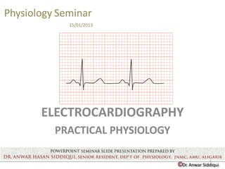
  • 1. ©Dr. Anwar Siddiqui Physiology Seminar 15/01/2013 ELECTROCARDIOGRAPHY PRACTICAL PHYSIOLOGY 1
  • 2. 2 INTRODUCTION  ECG is a three letter acronym for ElectroCardioGraphy.  The word is derived from electro(greek for electricity),cardio(greek for heart) and graph(Greek root meaning "to write“)  It is a transthoracic interpretation of the electrical activity of the heart over time captured and externally recorded by skin electrodes.  The device used to produce this non invasive record is called the electrocardiograph.  ECG is the gold standard for the noninvasive diagnosis of cardiac diseases and may occasionally be the only marker for the presence of heart disease.
  • 3. INDICATIONS OF ECG  Gold standard for diagnosis of cardiac arrhythmias  Helps detect electrolyte disturbances (hyper- & hypokalemia)  Allows for detection of conduction abnormalities  Screening tool for ischemic heart disease during stress tests  Helpful with non-cardiac diseases (e.g. pulmonary embolism or hypothermia An ECG is a diagnostic tool, NOT a treatment No one is ever cured by an ECG!! 3
  • 4. 4 ELECTROCARDIOGRAPHY TIMELINE  1872:Alexander Muirhead attached wires to a feverish patient's wrist to obtain a record of the patient's heartbeat St Bartholomew's Hospital.  1887:British physiologist Augustus D. Waller of St Mary's Medical School, London publishes the first human electrocardiogram. The trace from the heartbeat was projected onto a photographic plate which was itself fixed to a toy train  1893:Dutch physiologist Willem Einthoven introduces the term 'electrocardiogram' at a meeting of the Dutch Medical Association.  1895: Willem Einthoven distinguishes five deflections which he names P , Q, R, S and T
  • 5. 5 1902: Einthoven publishes the first electro - cardiogram recorded on a string galvanometer. 1912: Einthoven addresses the Chelsea Clinical Society in London and describes an equilateral triangle formed by his standard leads I, II and III later called 'Einthoven's triangle'. 1924: Willem Einthoven wins the Nobel prize for inventing the electrocardiograph.
  • 6. • Figure depicting Einthoven recording his first ECG in 1902 by placing limbs in buckets of conducting solution! 6
  • 7. 7 BASIC ELECTROPHYSIOLOGY PHYSIOLOGICAL PROPERTIES OF MYOCARDIAL CELL Automaticity: ability to initiate an impulse Excitability: ability to respond to a stimulus Conductivity: ability to transmit an impulse Contractility: ability to respond with pumping action Depolarization and repolarization of a cardiac cell generates action potential ECG is the composite representation of action potential of all cardiac cell.
  • 8. 8 ELECTRICAL CONDUCTION SYSTEM OF THE HEART  The electrical discharge for each cardiac cycle normally starts in a special area of the right atrium called the ‘sinoatrial (SA) node’.  Depolarization then spreads through the atrial muscle fibres.  There is a delay while the depolarization spreads through another special area in the atrium, the ‘atrioventricular (AV) node’.  Thereafter, the electrical discharge travels very rapidly, down specialized conduction tissue: first a single pathway, the ‘bundle of His’, which then divides in the septum between the ventricles into right and left bundle branches.
  • 9.  Within the ventricular mass, conduction spreads somewhat moreslowly, through specialized tissue called ‘Purkinje fibres’. 9
  • 10. 10 Conduction speed of cardiac tissue TISSUE CONDUCTION RATE (m/s) SA node 0.05 Atrial pathway 1 AV node 0.05 Bundle of His 0.05 Purkinje system 4 Ventricular muscle 1
  • 11. 11 CONDUCTION OF THE IMPULSE: Normal resting membrane potential=-90mv If the potential rises from -90 to 0, then this excites a further rise of potential, called the action potential. The action potential is transmitted throughout the cell and forms the impulse. During the rise of potential, the membrane becomes permeable to Sodium ions and the potential rises to a positive direction. This phenomena is called depolarization. The Sodium channels close and there is rapid diffusion of K+ ions into the exterior, reestablishing the resting membrane potential. This is called  Depolarization is followed by muscle contraction and repolarisation is followed by muscle relaxation.
  • 12. • Fig depicting the mechanism of depolarisation and repolarisation Depol Repol 12 Restoration of ionic balance
  • 13. NORMAL SINUS RYTHEM The adjacent figure shows the normal sinus rythem A normal sinus rythem comprises of the following waves:- •P waves- denotes atrial depolarization(electrical vector is directed from the SA node towards the AV node) • QRS complex- denotes depolarization of ventricles as well as repolization of atrium •T waves- denotes the repolarization (or recovery) of the ventricles. The interval from the beginning of the QRS complex to the apex of the T wave is referred to as the absolute refractory period. The last half of the T wave is referred to as the relative refractory period. As depicted in the fig:- •PR interval- beginning of the P wave to the beginning of the QRS complex •ST segment- connects the QRS complex and the T wave. •QT interval- the beginning of the QRS complex to the end of the T wave. 13
  • 14. What differentiates a segment from an interval?  A segment is a straight line connecting two waves.  An interval encompasses at least one wave plus the connecting straight line. 14
  • 15. 15  J point- J-point is the point at which the QRS complex meets the ST wave.  Its an isoelectric point and its importance lies in the fact that ST segment elevation is measured with respect to it  J WAVE AND U WAVE:These are two abnormal waves that may be seen sumtime in the ecg recordings. o J wave • also known as camel-hump sign, late delta wave, hathook junction, hypothermic wave, prominent J wave ,[1] K wave, H wave or current of injury • positive deflections occurring at the junction between the QRS complex and ST segment(j point) • observed in people suffering from hypothermia with a temperature of less than 32 o U wave • typically small, and, by definition, follows the T wave • Prominent U waves are most often seen in hypokalemia, but may be present in hypercalcemia, thyrotoxicosis
  • 16. Fig representing the J point Fig representing the J wave in an hypothermic individual The arrow in the figure represents the U wave in a hypokalemic patient 16
  • 17. 17 RECORDING THE ELECTROCARDIOGRAM THE E.C.G PAPER  ECG machines record changes in electrical activity by drawing a trace on a moving paper strip.  The electrocardiograph uses thermal paper, which is a graph paper & runs normally at a speed of 25mm/sec  Time is plotted on the X axis & voltage is plotted on the Y axis.  In X axis, 1 second is divided into 5 large squares each of which represents 0.2 sec. Each large square is further divided into 5 small squares which represents 0.04 sec.  The ECG machine is calibrated in such a way that an increase of voltage by 1 mVolt should move the stylus vertically by 1cms.
  • 18. ECG PAPER • Fig adjacent shows a callibration graph.By callibration we mean that an increase of voltage by 1mVolt should move the stylus vertically by 1cms. . The calibration signal should be included with every record 18
  • 19. 19 ELECTROCARDIOGRAPHIC LEADS - CONVENTIONAL  12 conventional leads, physiologically divided into two groups viz: Bipolar leads- 3 Standard limb leads Unipolar leads-3 Augmented limb leads and 6 precordial chest leads  Bipolar leads : These record the actual difference in potential across the two electrodes. There are three standard limb lead:- • Lead I Left arm Right arm • Lead II Left foot Right arm • Lead III Left foot Left arm o The lead axes form the sides of an equilateral triangle with the heart at the center ( Einthoven's triangle)
  • 20. 20 o The sum total of the potential in the three leads equals zero and mathematically it co uld be demonstrated that the potential in L II equals sum of the potentials in L I and L III i.e, Einthoven's law.  Unipolar limb leads: • Constituted by the indifferent electrode which forms the negative electrode and the exploring electrode which forms the positive electrode. • The indifferent electrode is constituted by connecting all limb lead electrodes together through an electrical resistance there by maintaining the zero potential. The positive electrode records the true potential at a given point. Here the record is of low voltage. • Goldberger augmented these leads for proper recording,came to be known as augmented unipolar limb leads, represented by aVR, aVF, aVL leads
  • 21. According to Kirchhoff's law these lead voltages have the following relationship: VI + VIII = VII 21
  • 22.  Unipolar chest leads  Constituted by an indifferent electrode resulting from a connection between all three standard limb leads and an exploring electrode placed on 6 different points on the chest wall.  The indifferent electrode forms the negative terminal &the exploring electrode forms the positive terminal.  Placement of precordial leads. V 1 - 4th intercostal space , right of sternum. V 2 - 4th ICS left of sternum V 4 - 5th ICS midclavicular line V 3 - Midway between V2 and V4 V 5 - 5th ICS anterior axillary line. V 6 - 5th ICS mid axillary line. 22
  • 23. Diagram depicting the einthoven’s Triangle along with the position of various electrodes used in the ECG Legend: RA-right arm LA-left arm L leg-left leg V1 to V6-precordial chest lead aVR-augmented vector right arm aVL-augmented vector left arm aVF-augmented vector left foot 23
  • 24.  Leads I, II and aVL look at the left lateral surface of the heart  leads III and aVF at the inferior surface, and lead aVR looks at the right atrium  The V leads are attached to the chest wall by means of a suction electrode • leads V1 and V2 look at the right ventricle • V3 and V4 look at the septum between the ventricles and the anterior wall of the left ventricle • V5 and V6 look at the anterior and lateral walls of the left ventricle 24
  • 25. • An overview of the electrocardiographic leads 25
  • 26. 26 MAKING A RECORDING  Good contact between body surface and electrode is necessary. It might be essential to shave the chest and apply electro cardio graphic jelly  The patient must lie down and relax to prevent muscle tremor  Connect up the limb electrodes to the correct limb.limb electrodes have marking on them and also they are colour coded(red –right arm,yellow-left arm,gren left leg and black-right leg)  Calibrate the record with 1mv signal.There shouldn’t be overdamping or underdamping.  Any metallic object like watch or jwelleary should be removef from the patients body  4-5 recording of each lead is recorded
  • 27. 27 FUNDAMENTAL PRINCIPLES BEHIND THE RECORDING  An electromagnetic force, current or vector has both magnitude and direction. When this force is directed to the positive electrode of a lead, the ECG will record an upward or positive deflection  When the vector is directed away from the positive electrode the ECG will record a downward or negative deflection, if at 90degree to the electrode the wave touches the baseline  physiologically, left ventricle and inter ventricular septum constitutes the dominant part,and hence maximally influences variations in ECG.
  • 28. WAVES FORMATION A wave of depolarisation moving away from the elec trode causes negative deflewctio2n8 A wave of depolarisation moving toward a positive electrode records a positive deflection
  • 29. • EKG recording if the positive electrode is placed in the middle of the cell 29
  • 30.  We can easily apply these concepts to the entire heart.  Electrodes placed on the surface of the body will record waves of depolarization and repolarization as they sweep through the heart. 30
  • 31. 31 HOW TO REPRT AN ECG  Ecg strip should be correctly labelled(the patients particular and all the lead markings)  The ecg recording should be described under the following heads: • Heart rate • Rythem • Various conduction intervals (pr interval ,qt interval) • Description of QRS complex ,ST segment and T waves • Cardiac axis • Any abnormal wave like J and U waves  Heart rate:calculated by dividing 1500 by number of small box between two consecutive R waves • Sinus tachycardia-heart rate more than 100 beats per minute. • Sinus bradycardia-heart rate less than 60 beats per minute
  • 32. 32  Rhythm- rhythm controlled by sinus node at a rate of 60-100 beats/min; each P wave followed by QRS and each QRS preceded by a P wave. Specific Arrhythmias • Sinus bradycardia • Sinus tachycardia • Sick sinus syndrome- disturbance of SA nodal function that results in a markedly variable rhythm (cycles of bradycardia and tachycardia). • Atrial flutter - sinus rate of 250-350 beats/min • AV nodal blocks - a conduction block within the AV node (or occasionally in the bundle of His) that impairs impulse conduction from the atria to the ventricles. • Ventricular flutter - very rapid ventricular depolarizations >250/min • Ventricular fibrillation - uncoordinated ventricular depolarizations; leads to death if not quickly corrected
  • 33. NORMAL SINUS RHYTHM Impulses originate at S-A node at normal rate 33 SINUS TACHYCARDIA Impulses originate at S-A node at rapid rate ATRIAL FLUTTER Impulses travel in circular course in atria – No interval between T and P
  • 34. ATRIAL FIBRILLATION Impluses have chaotic, random pathways in atria 34 VENTRICULAR TACHYCARDIA Impulse originate at ventricular pacemaker – odd/wide QRS complex VENTRICULAR FIBRILLATION Chaotic ventricular depolarization – ineffective at pumping blood – death within minutes
  • 35. A-V BLOCK, FIRST DEGREE Atrio-ventricular conduction lengthened P-wave precedes each QRS-complex but PR-interval is > 0.2 s 35 A-V BLOCK, SECOND DEGREE Sudden dropped QRS-complex Intermittently skipped ventricular beat
  • 36. 36  PR interval and QT interval • The PR interval extends from the start of the P wave to the very start of the QRS complex. • A normal value is 0.12 to 0.20 seconds • Its significance lies in assessing the nodal blocks • QT interval is a measure of the time between the start of the Q wave and the end of the T wave • Normal values for the QT interval are between 0.30 and 0.44 secs • If abnormally prolonged or shortened, there is a risk of developing ventricular arrythmias  QRS complex and ST segment • The QRS complex is 0.08 to 0.12 sec • Not every QRS complex contains a Q wave, an R wave, and an S wave • The duration, amplitude, and morphology of the QRS complex is useful in diagnosing, arrythmias, conduction abnormality, myocardialinfarction, and other disease states.
  • 37. 37 • ST segment connects theQRS complex and theT wave and has a duration of 0.08 to 0.12 sec • ST segment elevation or depression is associated with various cardiac abnormality Conditions causing ST segment elevation Acute myocardial infarction Pericarditis Left Ventricular Hypertrophy Left Bundle Branch Block hyperkalemia Conditions causing ST segment depression Ischemic heart disease Hypokalemia Secondary ST segment changes with conduction abnormalities (e.g., RBBB, LBBB, WPW, etc hypokalemia
  • 38. Morphology of ST segment elevation  AMI usually demonstrate straight/convex STE  Concave shaped STE-non AMI causes 38
  • 39. 39  Cardiac axis • The electrical axis of the heart is the mean direction of the action potentials traveling through the ventricles during ventricular activation (depolarization) • The QRS complex, which represents ventricular depolarization, is used for the determination of the electrical heart axis. • The normal electrical axis of the heart is situated between -30 degrees and +90 degrees (positive 90 degrees) with respect to the horizontal line • Left axis deviation: the electrical heart axis is between -30 degrees and -90 degrees with respect to the horizontal line. • Right axis deviation: the electrical heart axis is between +90 degrees and 180 degrees with respect to the horizontal line. • Extreme axis deviation (also known as northwest axis or no man’s land): the electrical heart axis is between +180 degrees and -90 degrees with respect to the horizontal line.
  • 40. Fig showing the cardiac axis in hexaxial referrance system causes of right axis deviation •normal finding in children and tall thin adults •right ventricular hypertrophy •chronic lung •anterolateral myocardial infarction •left posterior hemiblock •Wolff-Parkinson-White syndrome - left sided accessory pathway •atrial septal defect •ventricular septal defect 40
  • 41. 41 causes of left axis deviation • left anterior hemiblock • Q waves of inferior myocardial infarction • emphysema • hyperkalaemia • Wolff-Parkinson-White syndrome - right sided accessory pathway • tricuspid atresia • ostium primum ASD • injection of contrast into left coronary artery causes of a Northwest axis (no man's land) • emphysema • hyperkalaemia • lead transposition • artificial cardiac pacing • ventricular tachycardia
  • 42. REFERENCES • Only EKG Book You'll Ever Need, Thaler, Malcom S, 2007 Lippincott Williams & Wilkins 5th Edition • Schamroth L. Electrical axis. In : Schamroth C. (ed)An introduction to Electrocardiography, Blackwell Science Ltd. Massachusetts 1990; 34–48. • John.R.Hampton the ECG made easy 6th edition ,Churchill Livingstone publication theend… .. thank you 42