More Related Content
Similar to Angulated Abutments Clinical Results
Similar to Angulated Abutments Clinical Results (20)
Angulated Abutments Clinical Results
- 1. The Use of Angulated Abutments in
Implant Dentistry: Five-Year Clinical
Results of an Ongoing Prospective Study
Ashok Sethi, BDS, DGDP, MGDSRCS, DUI1/Thomas Kaus, Dr Med Dent, DDS2/Peter Sochor, ZTM3
A total of 2,261 2-stage implants was placed in 467 patients in combination with angled abutments
ranging from 0 to 45 degrees. These were observed over a period of up to 96 months, with a mean
observation time of 28.8 months. Single and multiple teeth were replaced and restored using angled
abutments. For patients who contributed multiple survival data, the data were considered dependent.
Therefore, a mean survival estimation was performed. With a certainty of 95%, an estimated mean
survival rate better than 98.6% after a 5-year observation period was calculated. The statistical comparison of 2 independent, randomized implant groups (with abutments angled between 0 and 15
degrees and between 20 and 45 degrees) by means of a log-rank test showed a probability of 0.84 (P
value) that the survival functions are the same for both groups. Good esthetic and functional outcomes were observed. (INT J ORAL MAXILLOFAC IMPLANTS 2000;15:801–810)
Key words: dental abutments, osseointegrated dental implants, survival analysis
T
he placement of endosseous dental implants has
become an increasingly common practice. Some
implants, especially some oral implants of the past,
are poorly documented or have not been followed up
for an adequate time period.1 It is important to use
an implant system that is adequately supported by
clinical reports. Well-documented implant systems
such as the Brånemark (Nobel Biocare, Göteborg,
Sweden) or Frialit-2 (Friadent, Mannheim, Germany) show high success rates. For follow-ups of
more than 5 years, the Brånemark System has shown
success rates of 85% to 100% in the maxilla and 93%
to 99% in the mandible.2,3 The Frialit-2 implant system has shown success rates of 97.6% when used for
single-tooth replacement and 98.8% in immediate
postextraction applications.4 Comparable success
rates have also been found by several other studies
and different dental implant systems.5–13
To date, there have been no long-term published
studies that have assessed the effect of non-axial
loading on the bone supporting the implants. The
anatomy of the jaws and the morphology of the
residual ridges determine the orientation and angulation of implant placement. Similarly, the position
and morphology of the teeth are determined by
esthetic and functional considerations. In the
majority of situations, there is a difference between
the long axis of the implant and the long axis of the
planned tooth replacement.
The purpose of this article was to present preliminary results of the clinical long-term behavior
of implants restored using a broad range of angulated abutments.
1Senior
MATERIALS AND METHODS
Lecturer, Department of Maxillofacial Implants, Medical
School, University of Lille 2, Lille, France.
2Senior Lecturer, Department of Prosthodontics, University of
Tuebingen, Tuebingen, Germany.
3Master Technician, Novadent Dental Laboratory, London, United
Kingdom.
Reprint requests: Dr Ashok Sethi, Centre for Implant and Reconstructive Dentistry, 33 Harley Street, London W1N 1DA United
Kingdom. Fax: +44-207-436-8979. E-mail: asethi@dircon.co.uk
COPYRIGHT © 2000 BY QUINTESSENCE PUBLISHING CO, INC. PRINTING
OF THIS DOCUMENT IS RESTRICTED TO PERSONAL USE ONLY. NO PART OF
THIS ARTICLE MAY BE REPRODUCED OR TRANSMITTED IN ANY FORM WITHOUT WRITTEN PERMISSION FROM THE PUBLISHER.
The study was designed prospectively and was performed at the Centre for Implant and Reconstructive Dentistry, London, United Kingdom. Since
March 1991, 467 patients (55% female) have been
included in the study. These patients were provided
with a total of 2,261 implants to replace missing
The International Journal of Oral & Maxillofacial Implants
801
- 2. SETHI ET AL
Table 1 Distribution of Implants Placed
According to Location and Gender
Gender/Arch
Female
Maxilla
Mandible
Male
Maxilla
Mandible
Total
No. of
arches
No. of
implants placed
194
111
831
420
168
80
553
680
330
2261
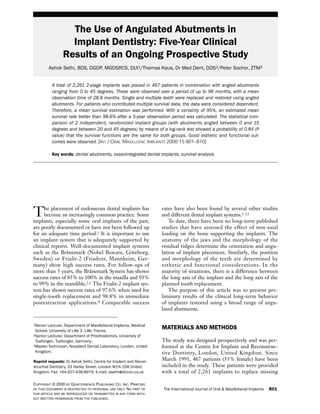
Fig 1 Cross-sectional image of a CT scan showing a maxillary
implant, in the planning stage, positioned between the labial and
palatal cortical plates. With the pre-angled abutment attached, it
lies within the prosthetic envelope defined by the radiopaque
marker on the labial surface and the mandibular incisor. The
abutment therefore emerges within the space allocated for the
restoration.
teeth with fixed restorations or to provide support
and retention for removable prostheses. The patient
group comprised 256 females and 211 males with an
age range from 17 to 83 years at the date of implant
surgery. The mean age was 49.6 years. The distribution of implants placed is given in Table 1.
The implants used were custom-made, parallelsided, commercially pure titanium screws with a
machined surface. The implants had an internal hex
and thread to provide positive location and a means of
securing the abutment to the implant. The machined
pre-angled abutments had an external hex to orient to
the implant and a screw to secure them to the implant.
These were manufactured from titanium alloy at angles
ranging from 0 to 45 degrees in 5-degree increments.
Patient Selection
All patients at the Implant Centre who chose dental
implants as a treatment option, or patients who
were referred for implant treatment to the Centre
for Implant and Reconstructive Dentistry, were
included in the study if there were no contraindications for implant treatment.
Treatment Procedure
The treatment procedure included a diagnostic
phase, a pre-implant surgical phase for augmentation
if necessary, a surgical phase for the placement and
exposure of the implants in 2 stages, and a prosthetic
phase. A maximum number of implants of the largest
possible dimension was placed in each arch according to the surgical protocol summarized below.
802
Volume 15, Number 6, 2000
Diagnostic Protocol. Clinical examination was carried out to assess the status and the periodontal tissues of any remaining teeth. Clinical examination
also included assessment of occlusal and parafunctional status and the soft tissues, including attached
gingiva, muscle attachments, and the lip line.
Radiographic examination was carried out for all
patients, including an orthopantomograph and
other radiographs as required. Periapical radiographs were taken for assessment of detail, lateral
cephalographs for the assessment of bone width in
the midline and facial profile, and computed tomographic (CT) scans for the assessment of bone volume and quality in patients requiring multiple
implants, particularly in the posterior mandible.
Furthermore, CT scans were used for the assessment of abutment angulation (Fig 1).
A diagnostic preview (via an arrangement of teeth
in wax) was used to establish the most esthetically
pleasing and functionally viable tooth position. A
diagnostic template was fabricated over the plaster
duplicate of the preview to outline the prosthetic
envelope within which the abutment must fit. 14
Where inadequate bone was present, a variety of
procedures were used to augment the region, either
prior to the placement of implants or at the time of
implant placement.
Implant Surgery. Implant Placement. Access to the
bony ridge was obtained using remote incisions
whenever possible. Remote palatal incisions were
used in the maxilla, and remote buccal incisions
were used in the mandible. The implant sites were
COPYRIGHT © 2000 BY QUINTESSENCE PUBLISHING CO, INC. PRINTING
NO PART OF
THIS ARTICLE MAY BE REPRODUCED OR TRANSMITTED IN ANY FORM WITHOUT WRITTEN PERMISSION FROM THE PUBLISHER.
OF THIS DOCUMENT IS RESTRICTED TO PERSONAL USE ONLY.
- 3. SETHI ET AL
Fig 2a Implants in situ, placed using a diagnostic template to
identify the site for the implant osteotomy. Implant angulation is
determined anatomically, with the implants placed between the
cortical plates.
selected and a diagnostic template was used whenever appropriate. The treatment procedure was
modified on the basis of bone quality and jaw shape
according to Lekholm and Zarb.15
Osteotomies were prepared within the available
bone and between the labial and palatal cortical
plates. Internally irrigated osteotomy burs were
used in the mandible and maxilla at speeds ranging
from 1,000 to 2,000 RPM. Sterile saline was delivered by an internal cannula to the cutting edges of
the burs. 16 The burs were used to create the
osteotomy atraumatically and precisely and as a
gauge to measure the depth of the osteotomy. The
diameter of the osteotomy was enlarged incrementally using gradually wider burs matched to the
implant diameters.
Bone taps were used in types 1 and 2 bone for all
implant diameters and in type 3 bone for 4.5-mmand 5.5-mm-diameter implants, because of the
increased torque required for implant placement.
Socket formers were used in the maxilla, either by
themselves or in conjunction with ridge expanders
and/or osteotomy burs, depending on the clinical
situation. In types 3 and 4 bone socket formers that
matched the implant diameter were used to create
the osteotomy. For thin maxillary ridges, socket formers were used in conjunction with ridge expanders
to widen narrow maxillary ridges.17 Osteotomy burs
were used to determine depth and prepare the apical area in dense bone. In the posterior maxilla,
where limited bone height was present, socket formers were used to raise the sinus floor to create
height, using sinus floor manipulation.18–21 This
was done in conjunction with osteotomy burs.
Abutment Alignment and Selection. Abutment
alignment and selection were carried out during
first-stage surgery (implant placement) using try-in
COPYRIGHT © 2000 BY QUINTESSENCE PUBLISHING CO, INC. PRINTING
OF THIS DOCUMENT IS RESTRICTED TO PERSONAL USE ONLY. NO PART OF
THIS ARTICLE MAY BE REPRODUCED OR TRANSMITTED IN ANY FORM WITHOUT WRITTEN PERMISSION FROM THE PUBLISHER.
Fig 2b Zero-degree try-in abutments are inserted into the
implants, demonstrating the divergent angulation of the abutments. This is caused by the morphology of the maxilla, whose
base forms a smaller arc than the alveolar crest.
Fig 2c Correctly angled try-in abutments in place, showing parallelism and alignment, which will facilitate the prosthetic restoration.
abutments ranging from 0 to 45 degrees in 5-degree
increments.22 The try-in abutments corresponded
to definitive abutments and were used in conjunction with the diagnostic template (Figs 2 and 3).
Restorative angles and plane of orientation were
evaluated for the screw-retained abutments (or
angled healing abutments) so that pre-machined
definitive abutments would be available at secondstage surgery. The restorative angle and orientation
were noted on the patient record form and data
sheet. The wound was closed; the primary provisional prosthesis was then modified to compensate
for any alteration in the gingival contours and fitted.
Implant Exposure. This procedure was carried out
6 months after implant placement for both
mandibular and maxillary implants. The implant
was exposed and the cover screw was removed. The
pre-angled abutments that were selected at the time
of implant placement were seated (Fig 4), and the
The International Journal of Oral & Maxillofacial Implants
803
- 4. SETHI ET AL
Fig 3a A try-in abutment at first-stage surgery for a single-tooth
replacement is selected to fit within the prosthetic envelope as
outlined by the diagnostic template.
Fig 3b Multiple try-in abutment positions are verified for
mesiodistal and buccopalatal alignment using a diagnostic template. This is to ensure adequate space for prosthetic reconstruction.
angle and orientation of the abutments were confirmed using the template. The height of each abutment was also assessed using the template and the
patient’s occlusion and was modified if necessary.
The fixing screw was inserted through the correctly aligned and seated abutment and tightened to
32 Ncm, using countertorque applied via artery forceps. Primary stability of the implant was confirmed
by percussion and the absence of turning when
rotational forces were applied to the implant while
tightening the screw. The hex hole of the screw was
filled with wax, and the screw access hole was sealed
with a glass-ionomer cement. Implant sites were
allowed to heal for a period of 4 weeks prior to the
fabrication of definitive restorations.
Transitional Restorations. Transitional restorations
were fabricated from acrylic resin to provide the
patients with esthetic and functional restorations,
fitted at the time of abutment attachment. The
design of the restoration was based on the diagnostic
preview or try-in and allowed the transfer of tooth
form and position. The restorations were fabricated
hollow to receive the abutment and were relined at
the time of exposure. In a limited number of
patients, pre-angled healing abutments were used;
on these occasions, the provisional restoration was
appropriately modified for the transitional period.
Prosthetic Phase. Fixed restorations were fabricated as single crowns supported by 1 implant, or as
a prosthesis supported by multiple implants using
splinted crowns. Most fixed restorations were
cement-retained and were fabricated using conventional laboratory protocol for conventional cementretained restorations. Thirty-eight implants supported connected restorations, and 2 single crowns
used lateral fixation screws for supplementary retention. One restoration was fabricated for screw
retention and was supported by 6 implants.
For removable restorations, a variety of protocols
was used. A total of 24 implants was placed for the
retention of dentures; 1 implant failed and was subsequently replaced. Removable prostheses were
retained using ball attachments, bar and clips, and
attachments mounted on bars.
Implants used to stabilize traditional removable
prostheses primarily provided retention. Thus, these
prostheses were supported by both implants and soft
tissues. Four implants in the maxilla and 2 in the
mandible were used for the retention of these prostheses. The number of stages varied considerably,
depending upon the mechanism used for retention.
Patient Recall. Follow-up of patients after prosthetic restoration was performed according to the
protocol given in Table 2. Radiographs were normally obtained after implant placement, 1 week
after loading, at 6, 12, 18, and 24 months after
placement of the definitive prosthetic restoration,
804
OF THIS DOCUMENT IS RESTRICTED TO PERSONAL USE ONLY.
Fig 4 Occlusal view of multiple definitive abutments attached
at second-stage surgery. These lie within the space allocated for
each tooth of the restoration (as verified by the template) and can
be seen to be aligned with each other.
Volume 15, Number 6, 2000
COPYRIGHT © 2000 BY QUINTESSENCE PUBLISHING CO, INC. PRINTING
NO PART OF
THIS ARTICLE MAY BE REPRODUCED OR TRANSMITTED IN ANY FORM WITHOUT WRITTEN PERMISSION FROM THE PUBLISHER.
- 5. SETHI ET AL
and annually thereafter. To assess bone levels, periapical radiographs were taken using the long-cone
technique and Rinn paralleling system (RinnXCP
film holders, Rinn Corporation, Elgin, IL). When
periapical radiographs did not provide an accurate
result, orthopantomographs provided a radiographic overview (Planmeca PM 2002 CC Proline
panoramic x-ray, Planmeca Oy, Helsinki, Finland).
Clinical assessment involved visual examination,
recording of clinical parameters (bleeding on probing, pocket depth, and implant mobility), as well as
occlusal examination in centric relation and during
lateral excursions. Patient feedback and any complications were addressed as appropriate. When necessary, oral hygiene instructions were given to ensure
that a plaque-free environment could be maintained. The ideal aid to oral hygiene was selected
based on access. This was confirmed by plaque disclosure at each visit, and the technique was modified until the appropriate level of hygiene was
achieved.
Table 2
Follow-up Protocol
Time since loading
1 week
1 month
3 months
6 months
12 months
18 months
24 months
Every 2-3 years
Procedure
Clinical assessment
Baseline radiographs
Oral hygiene instruction
Clinical assessment
Clinical assessment
Oral hygiene instructions
Clinical assessment
Radiographs
Oral hygiene instructions
Clinical assessment
Radiographs
Oral hygiene instructions
Clinical assessment
Radiographs
Oral hygiene instructions
Clinical assessment
Radiographs
Oral hygiene instructions
Prosthesis removed for
assessment of individual implants
Calculations and Statistics
All calculations were carried out using a personal
computer. The data were transferred into a database
format (Microsoft Access, Microsoft, Redmond,
WA). Statistical analyses were performed with a statistical program (JMP, SAS Institute Inc, Cary, NC).
Because some patients contributed multiple survival data, dependent information from the data
could not simply be excluded.23 Therefore, a mean
survival estimation according to Aalen et al24 was
performed using SAS software (SAS Institute Inc).
To compare survival estimates according to the
Kaplan-Meier method, a 1-implant-per-patient
selection, supported by a randomization procedure,
was performed to obtain independent information
from the data.25 This was performed as follows: for
each patient who contributed multiple survival data,
only 1 implant was chosen for survival analysis. In
situations where 1 or more of a patient’s implants
failed, only 1 of the failures was considered for
analysis. Either the failed implant that was placed
first or, in cases where several failed implants were
placed at the same time, only 1 of the failures was
chosen by computerized randomization. In cases
where none of the implants had failed thus far, only
the implant that was placed first was considered for
analysis. A computerized randomization was performed when several implants had been placed at
the same time. This data selection was considered as
worst-case selection. Survival curves were then
compared using the log-rank test.26
COPYRIGHT © 2000 BY QUINTESSENCE PUBLISHING CO, INC. PRINTING
OF THIS DOCUMENT IS RESTRICTED TO PERSONAL USE ONLY. NO PART OF
THIS ARTICLE MAY BE REPRODUCED OR TRANSMITTED IN ANY FORM WITHOUT WRITTEN PERMISSION FROM THE PUBLISHER.
RESULTS
Patients Lost to Follow-up
There were 467 patients with a total of 2,261
implants included in the study. Eighty-one patients
(17.3%) with a total of 379 implants (16.8%) were
lost to follow-up. Fifty-five patients (11.8%) were
referred patients who did not attend the recall program and were monitored by their referring dentist.
Fourteen patients (3%) did not comply with
requests to attend for monitoring, 8 patients (1.7%)
moved away from the area and were unable to
attend regularly, and 4 patients (0.8%) are deceased.
The reasons for loss of follow-up are summarized in
Table 3.
Intraoperative Complications
In the posterior mandible, no damage to the inferior dental nerve (IDN) took place because the
depth of the osteotomy was measured to be 2 mm
clear of the IDN. When implants were placed in
the anterior mandible, the mental foramen was
exposed and the osteotomies prepared so that the
completed osteotomy was at least 3 mm anterior to
the foramen.
Placement of implants in the maxilla involved the
engagement of the opposing cortical plate whenever
possible. In a small but unrecorded number of
osteotomy preparations, the nasal or sinus floor was
inadvertently perforated. The implant length that
was selected reached only to 1.0 mm below the point
at which the perforation took place. Therefore, no
The International Journal of Oral & Maxillofacial Implants
805
- 6. SETHI ET AL
Table 3
Patients Lost to Follow-up
Reason for loss
Referred patients not attending recall
Non-compliance
Patient moved away
Deceased
Total
No. of patients
55 (11.8%)
14 (3%)
8 (1.7%)
4 (0.8%)
81 (17.3%)
were more than 10 mm long. Figure 6, depicting
the frequency of diameters used, demonstrates that
the majority of implants used were 3.75 mm in
diameter. A disproportionately small number of 5.5mm implants were used because they were only
recently introduced to the practice (1997).
Frequency of Abutment Angulations
implants were placed into the sinus or the nasal
floor, and no adverse consequences were noted.
Because of the protocol concerning the anatomic
placement of implants between the cortical plates,
very few incidences of dehiscence through the labial
or cortical plates were noted. These were not
recorded and were not considered significant.
Postoperative Complications
Infection originating from the cover screw dead
space did occur. Twelve implants were treated by
removing the cover screw and, while irrigating the
internal hex and thread, introducing an antibiotic
(gentamicin) and reinserting the cover screw. This
led to uneventful healing.
Soft tissue breakdown was seen, which led to
premature exposure of 15 implants. The implants
that were prematurely exposed were treated by
uncovering the implants and attaching healing abutments, which were left unloaded for the remainder
of the 6-month healing period. None of the
implants treated in this way failed.
Implant Loss
A total of 2,261 implants was placed between March
1991 and May 1999; of these, 38 implants failed during the observation period, and 2,223 remain in situ.
Twelve implants failed prior to exposure because of
infection, and 16 implants failed at exposure. Three
implants failed before prosthetic treatment could be
started as a result of excessive bone loss around the
implants. The cause for this has not been determined. Two implants failed prior to completion of
the restorative phase. Five implants were lost after
the completion of the restorative phase, but 3 of
these implants were successfully replaced and connected to the existing prosthesis. Two implants were
not replaced, but the restorations continue to function, since the implants were considered unnecessary
for the long-term survival of the restorations.
Frequency of Implant Lengths and Diameters
Figure 5 depicts the frequency of different implant
lengths used. The majority of the implants (92%)
806
Volume 15, Number 6, 2000
The entire range of angles available was used and is
depicted in Fig 7. The majority of the angles used
ranged between 5 and 30 degrees (2,039 or 90.2%).
A small number (222 or 9.8%) of 0-, 35-, 40-, and
45-degree abutments were also used. This enabled a
greater number of patients to be treated without
compromise of ideal implant placement according
to available anatomic conditions.
There were no implant or abutment failures
associated with the use of angled abutments. Furthermore, there was no incidence of screw loosening associated with angled abutments. The use of
angled abutments allowed restorations to be parallel
and aligned with each other. Cement-retained prostheses could be fabricated for these patients, which
furthermore allowed them to be connected
together, providing cross-arch splinting as well as
facilitating the management of failed implants.
Survival Analysis
The duration of observation since placement of the
implants was betwen 0 and 96 months, with a mean
observation time of 28.8 months. Figure 8 depicts
the distribution of implants with regard to time
since placement. Fifty percent (median) of all
implants were placed within 21.6 months prior to
the last observation. In addition, the box plot shows
the 25% quartile (9.9 months) and the 75% quartile
(41.7 months).
Figure 9 depicts the mean survival estimation
following placement, according to Aalen et al.24 For
each patient who contributed multiple survival data,
the data were considered dependent. After an observation time of 60 months (5 years) after placement,
the calculated 95% confidence interval of the mean
survival estimation according to Aalen et al24 was
99% (± 0.4%). Therefore, with a certainty of 95%,
the mean survival probability after 5 years can be
considered better than 98.6%.
Figure 10 depicts the survival analysis of 2
selected groups of implants. A total of 467 implants
was selected according to the aforementioned
“worst-case” selection procedure. The survival
analysis according to Kaplan-Meier of implants
with abutment angulation of more than 15 degrees
(n = 219) was compared with implants restored with
abutments that were angulated at 0 to 15 degrees
COPYRIGHT © 2000 BY QUINTESSENCE PUBLISHING CO, INC. PRINTING
NO PART OF
THIS ARTICLE MAY BE REPRODUCED OR TRANSMITTED IN ANY FORM WITHOUT WRITTEN PERMISSION FROM THE PUBLISHER.
OF THIS DOCUMENT IS RESTRICTED TO PERSONAL USE ONLY.
- 7. SETHI ET AL
Fig 5 Frequency of implant lengths used in
the patient population.
320
293
No. of implants
300
215
184
200
101
100
31
4
7
Fig 6
249 244
216
123
106
126
49
8
9
10 11 12 13 14 15 16 17 18 19 20
Implant length (mm)
Frequency of implant diameters used.
1,356
No. of implants
1250
1000
750
564
500
250
180
99
3
62
5.5
2.75
Fig 7
used.
3.75
4.5
Implant diameter (mm)
Frequency of abutment angulations
No. of implants
447
471
437
400
300
267
240
177
200
100
0
COPYRIGHT © 2000 BY QUINTESSENCE PUBLISHING CO, INC. PRINTING
OF THIS DOCUMENT IS RESTRICTED TO PERSONAL USE ONLY. NO PART OF
THIS ARTICLE MAY BE REPRODUCED OR TRANSMITTED IN ANY FORM WITHOUT WRITTEN PERMISSION FROM THE PUBLISHER.
80
74
5
10
15
20 25
30
35
Abutment angulation (deg)
47
40
21
45
The International Journal of Oral & Maxillofacial Implants
807
- 8. SETHI ET AL
No. of implants
9.9
Mean
28.6
Fig 8 Distribution of implants according to
time since placement (histogram and box plot
with 25% and 75% quartiles).
41.7
21.6
Median
600
400
200
Survival probability (%)
0
10
20 30 40 50 60 70 80
Time at risk since placement (mo)
100
Fig 9 Mean survival estimation according to
Aalen et al.24
100
90
80
70
60
50
40
30
20
10
0
95% confidence interval (upper limit)
95% confidence interval (lower limit)
0
10
20 30 40 50 60 70 80
Time at risk since placement (mo)
90 100
(n = 248). Statistical comparison of the groups by
means of a log-rank test showed a probability of
0.84 (P value) that the survival functions are the
same for both groups.
DISCUSSION
Historically, the need to change the abutment angle
has been recognized, as a result of the difference in
angulation between the bone available for implant
placement and the long axis of the planned restoration. However, there have been concerns expressed
about the adverse effect of non-axial forces on the
survival of implants. These have been investigated by
means of photoelastic studies as well as 3-dimensional
finite element computer simulations.27–29 However,
these in vitro investigations do not address the biologic response of bone to functional loads.
808
90
Volume 15, Number 6, 2000
Goodship and coworkers have demonstrated the
capacity of bone to remodel in response to strain.30
To date, no long-term studies have been published
that have assessed the effect of non-axial loading on
the bone supporting the implants or on the component parts transmitting these forces to the supporting bone.31,32
The results of this study demonstrate that there
seems to be no difference in the survival of implants
based on the use of angulated abutments ranging
from 0 to 45 degrees. Balshi et al have also demonstrated that the survival of implants loaded via 30degree abutments is not significantly different from
implants loaded via straight abutments.31 As demonstrated by the present results, the survival of implants
loaded via angulated abutments is comparable to
other reported studies in which angulated abutments
were not used or addressed.2–13
COPYRIGHT © 2000 BY QUINTESSENCE PUBLISHING CO, INC. PRINTING
NO PART OF
THIS ARTICLE MAY BE REPRODUCED OR TRANSMITTED IN ANY FORM WITHOUT WRITTEN PERMISSION FROM THE PUBLISHER.
OF THIS DOCUMENT IS RESTRICTED TO PERSONAL USE ONLY.
- 9. SETHI ET AL
The protocol that was used for this study involved
the placement of implants anatomically within the
available bone, irrespective of the angle between the
long axis of the implant and proposed prosthetic
crown. This approach served several purposes:
The abutments were selected at first-stage
surgery, which reduced the number of component
parts required. Alignment of each implant hex and
abutment at this stage made it possible to overcome
many of the difficulties associated with the laboratory correction of non-aligned implants and abutments. The planning of treatment was greatly simplified, since complex surgical templates based on
CT scans to guide the osteotomy preparation did
not need to be fabricated.33,34
Most importantly, there appeared to be a comparable high survival rate and an esthetic and functional outcome that was consistently achieved. This
may be attributable to the improved biomechanics
that result from the use of angled pre-machined
abutments, which are selected and aligned to lie
within the prosthetic envelope to facilitate the
restorative phase. Cement-retained restorations
could be fabricated, which are technically easier to
fabricate than stress-inducing screw-retained
restorations.35–37
Because of the mean observation time of 29
months, less than half of the 2,261 placed implants
could be considered for the calculation of the survival probability after 5 years. These factors may
contribute to the high survival rate of 98.6% after a
5-year observation period considering the 95% confidence interval of the mean survival estimation
according to Aalen et al (99 ± 0.4%). Additionally,
as a result of the lack of events (failures) after 35
months, the estimated success rate after 5 years
must be considered preliminary.
COPYRIGHT © 2000 BY QUINTESSENCE PUBLISHING CO, INC. PRINTING
OF THIS DOCUMENT IS RESTRICTED TO PERSONAL USE ONLY. NO PART OF
THIS ARTICLE MAY BE REPRODUCED OR TRANSMITTED IN ANY FORM WITHOUT WRITTEN PERMISSION FROM THE PUBLISHER.
90
80
Survival probability (%)
• It enabled implants of a greater dimension
(length and diameter) to be placed.
• It enabled a greater number of patients to be
treated.
• It avoided surgical compromise by allowing the
implants to be placed between the cortical plates,
thus preventing perforations and dehiscences.
• It allowed the permucosal site to be placed more
anatomically and facilitated restoration esthetically, functionally, and phonetically.
• It improved the efficiency of the treatment by
reducing treatment planning and clinical and laboratory time.
• It improved access for oral hygiene.
100
> 15-degree angulation (n = 219)
70
≤ 15-degree angulation (n = 248)
60
50
40
30
20
Log-rank test P value = .84
10
0
0
10
20 30 40 50 60 70 80
Time at risk since exposure (mo)
90
Fig 10 Survival analysis according to Kaplan-Meier. Selected
groups are compared according to abutment angulation.
CONCLUSION
Angulated abutments may be used without compromising the long-term survival of implants. Treatment
planning can be facilitated and implant placement
can be carried out without surgical compromise. The
fabrication of restorations utilizes conventional
restorative procedures. Good esthetic and functional
outcomes can be easily achieved using the protocol
outlined.
ACKNOWLEDGMENT
The authors wish to acknowledge the assistance and statistical
support provided by Dr rer nat Detlef Axmann-Krcmar,
Department of Prosthodontics, University of Tuebingen, especially for introducing the mean survival estimation method
according to Aalen et al to our data.
REFERENCES
1. Albrektsson T, Sennerby L. State of the art in oral implants.
J Clin Periodontol 1991;18:474–481.
2. Albrektsson T. A multicenter report on osseointegrated oral
implants. J Prosthet Dent 1988;60:75–84.
3. Albrektsson T, Dahl E, Enbom L, Engevall S, Engquist B,
Eriksson AR, et al. Osseointegrated oral implants. A Swedish
multicenter study of 8139 consecutively inserted Nobelpharma implants. J Periodontol 1988;59:287–296.
The International Journal of Oral & Maxillofacial Implants
809
- 10. SETHI ET AL
4. Gomez-Roman G, Schulte W, d’Hoedt B, Axman-Krcmar
D. The Frialit-2 implant system: Five-year clinical experience in single-tooth and immediately postextraction applications. Int J Oral Maxillofac Implants 1997;12:299–309.
5. Adell R, Eriksson B, Lekholm U, Brånemark P-I, Jemt T. A
long-term follow-up study of osseointegrated implants in
the treatment of totally edentulous jaws. Int J Oral Maxillofac Implants 1990;5:347–359.
6. Babbush CA, Shimura M. Five-year statistical and clinical
observations with the IMZ two- stage osteointegrated
implant system. Int J Oral Maxillofac Implants 1993;8:
245–253.
7. Block MS, Kent JN. Long-term follow-up on hydroxylapatite-coated cylindrical dental implants: A comparison
between developmental and recent periods. J Oral Maxillofac Surg 1994;52:937–943.
8. Buser D, Mericske-Stern R, Bernard JP, Behneke A,
Behneke N, Hirt HP, et al. Long-term evaluation of nonsubmerged ITI implants. Part 1: 8-year life table analysis of
a prospective multi-center study with 2359 implants. Clin
Oral Implants Res 1997;8:161–172.
9. D’Hoedt B, Schulte W. A comparative study of results with
various endosseous implant systems. Int J Oral Maxillofac
Implants 1989;4:95–105.
10. Grunder U, Polizzi G, Goené R, Hatano N, Henry P, Jackson WJ, et al. A 3-year prospective multicenter follow-up
report on the immediate and delayed-immediate placement
of implants. Int J Oral Maxillofac Implants 1999;14:210–216.
11. Higuchi KW, Folmer T, Kultje C. Implant survival rates in
partially edentulous patients: A 3-year prospective multicenter study. J Oral Maxillofac Surg 1995;53:264–268.
12. Nevins M, Langer B. The successful application of osseointegrated implants to the posterior jaw: A long-term retrospective study. Int J Oral Maxillofac Implants 1993;8:428–432.
13. Wheeler SL. Eight-year clinical retrospective study of titanium plasma-sprayed and hydroxyapatite-coated cylinder
implants. Int J Oral Maxillofac Implants 1996;11:340–350.
14. Sethi A. Precise site location for implants using CT scans: A
technical note. Int J Oral Maxillofac Implants 1993;8:433–438.
15. Lekholm U, Zarb GA. Patient selection and preparation. In:
Brånemark P-I, Zarb GA, Albrektsson T (eds). Tissue-Integrated Prostheses: Osseointegration in Clinical Dentistry.
Chicago: Quintessence, 1985:199–209.
16. Lavelle C, Wedgwood D. Effect of internal irrigation on
frictional heat generated from bone drilling. J Oral Surg
1980;38:499–503.
17. Sethi A, Sochor P, Hills G. Implants and maxillary ridge
expansion. Indep Dent 1998;80–90.
18. Summers RB. The osteotome technique: Part 3—Less invasive methods of elevating the sinus floor. Compendium
1994;15:698,700,702–704.
19. Summers RB. A new concept in maxillary implant surgery:
The osteotome technique. Compendium 1994;15:152,
154–156,158.
810
Volume 15, Number 6, 2000
20. Summers RB. Sinus floor elevation with osteotomes. J
Esthet Dent 1998;10:164–171.
21. Tatum HJ. Maxillary and sinus implant reconstructions.
Dent Clin North Am 1986;30:207–229.
22. Sethi A, Sochor P. Predicting esthetics in implant dentistry
using multiplanar angulation: A technical note. Int J Oral
Maxillofac Implants 1995;10:485–490.
23. Altman DG, Bland JM. Statistics notes. Units of analysis. Br
Med J 1997;314:1874.
24. Aalen OO, Bjertness E, Sonju T. Analysis of dependent survival data applied to lifetimes of amalgam fillings. Stat Med
1995;14:1819–1829.
25. Kaplan EC, Meier P. Nonparametric estimation from
incomplete observations. J Am Stat Assoc 1958;53:457–481.
26. Altmann DG. Analysis of survival times. In: Altmann DG
(ed). Practical Statistics for Medical Research. London:
Chapman and Hall, 1991:365–395.
27. Clelland NL, Gilat A. The effect of abutment angulation on
stress transfer for an implant. J Prosthodont 1992;1:24–28.
28. Clelland NL, Gilat A, McGlumphy EA, Brantley WA. A
photoelastic and strain gauge analysis of angled abutments
for an implant system. Int J Oral Maxillofac Implants 1993;
8:541–548.
29. Tuncelli B, Poyrazoglu E, Koyluoglu AM, Tezcan S. Comparison of load transfer by angulated, standard and inclined
implant abutments. Eur J Prosthodont Restorative Dent
1997;5:85–88.
30. Goodship AE, Lanyon LE, McFie H. Functional adaptation
of bone to increased stress. An experimental study. J Bone
Joint Surg [Am] 1979;61:539–546.
31. Balshi TJ, Ekfeldt A, Stenberg T, Vrielinck L. Three-year
evaluation of Brånemark implants connected to angulated
abutments. Int J Oral Maxillofac Implants 1997;12:52–58.
32. Kallus T, Henry P, Jemt T, Jorneus L. Clinical evaluation of
angulated abutments for the Brånemark system: A pilot
study. Int J Oral Maxillofac Implants 1990;5:39–45.
33. Almog DM, Onufrak JM, Hebel K, Meitner SW. Comparison between planned prosthetic trajectory and residual bone
trajectory using surgical guides and tomography—A pilot
study. J Oral Implantol 1995;21:275–280.
34. Weinberg LA, Kruger B. Three-dimensional guidance system for implant insertion: Part I. Implant Dent 1998;7:
81–93.
35. Hebel KS, Gajjar RC. Cement-retained versus screwretained implant restorations: Achieving optimal occlusion
and esthetics in implant dentistry. J Prosthet Dent 1997;77:
28–35.
36. Jemt T, Rubenstein JE, Carlsson L, Lang BR. Measuring fit
at the implant prosthodontic interface. J Prosthet Dent
1996;75:314–325.
37. Kallus T, Bessing C. Loose gold screws frequently occur in
full-arch fixed prostheses supported by osseointegrated
implants after 5 years. Int J Oral Maxillofac Implants 1994;
9:169–178.
COPYRIGHT © 2000 BY QUINTESSENCE PUBLISHING CO, INC. PRINTING
NO PART OF
THIS ARTICLE MAY BE REPRODUCED OR TRANSMITTED IN ANY FORM WITHOUT WRITTEN PERMISSION FROM THE PUBLISHER.
OF THIS DOCUMENT IS RESTRICTED TO PERSONAL USE ONLY.