1. (12) United States Patent
Norris
US008410451B2
US 8,410,451 B2
Apr. 2, 2013
(10) Patent N0.:
(45) Date of Patent:
(54) NEUTRON FLUORESCENCE WITH
SYNCHRONIZED GAMMA DETECTOR
(75) Inventor: Wayne B. Norris, Santa Barbara, CA
(Us)
(73) Assignee: BOSS Physical Sciences LLC, Troy, MI
(Us)
( * ) Notice: Subject to any disclaimer, the term ofthis
patent is extended or adjusted under 35
U.S.C. 154(b) by 0 days.
(21) App1.No.: 13/263,785
(22) PCT Filed: Apr. 9, 2010
(86) PCT No.: PCT/US2010/030455
§ 371 (0X1),
(2), (4) Date: Oct. 10, 2011
(87) PCT Pub. No.: WO2011/002537
PCT Pub. Date: Jan. 6, 2011
(65) Prior Publication Data
US 2012/0037812 A1 Feb. 16, 2012
Related US. Application Data
(60) Provisional application No. 61/167,902, ?led on Apr.
9, 2009.
(51) Int. Cl.
G01N 23/22 (2006.01)
(52) US. Cl. ...................................... .. 250/393; 250/395
(58) Field of Classi?cation Search ................. .. 250/393
See application ?le for complete search history.
(56) References Cited
U.S. PATENT DOCUMENTS
3,463,922 A * 8/1969 Martinez, Jr. et al. 250/36301
3,781,564 A 12/1973 Lundberg
(Continued)
FOREIGN PATENT DOCUMENTS
EP 1882929 A 1/2008
JP 2099811 A 4/1990
(Continued)
OTHER PUBLICATIONS
Kwan et al., Bulk Explosives Detection Using Nuclear Resonant
Absorption Technique, Plasma Science, Jun. 2-5, 2003, p. 396.
(Continued)
Primary Examiner * Marcus Taningco
(74) Attorney, Agent, or Firm *Endurance Law Group,
PLC
(57) ABSTRACT
Method and apparatus for minimizing signal noise (20, 22) in
thermal, epithermal, and cold neutron ?uorescence processes
using neutron ?ux modulation and gamma ray detector pulse
gating synchronized to neutron time of ?ight (NTOF). The
apparatus includes a source (12) ofthermal, epithermal, and/
or cold neutrons, optionally switched between ?ux or power
settings in various embodiments, a gamma ray detector (14)
or detection system capable of either being turned ON and
OFF, in some embodiments, or else being told to regard or
disregard gamma ray signals (20, 22) in other embodiments,
a control mechanism (24), and either a target range detector
(26) or a prior measurement oftarget range, in embodiments
where the range remains ?xed. The gamma ray detector (14)
is synchronized to the NTOF by the control mechanism (24)
so that it remains switched OFF during the pulse period ofthe
neutron source (12) and for the subsequent NTOF so that any
nuisance signals (20, 22) arriving at the detector (14) during
these times are not detected or considered.
20 Claims, 7 Drawing Sheets
2. US 8,410,451 B2
Page 2
Us. PATENT DOCUMENTS 7,461,032 B2 12/2008 Heaton et a1.
7,501,624 B1 3/2009 Farrell et al.
A §?ggg 5232a 31 7,505,544 B2 3/2009 Jestice
4,613,756 A 9/1986 IWancZyk etal. 20023651521232 2% ggggg vBynetfl'l
476167833 A 10/1986 Geller 2002/0131543 A1 9/2002 Leiiirie a‘
2 $1323 gun?“ et a1~ 2003/0161526 A1 8/2003 Jupiter et al.
479417162 A M990 V553? t l 2003/0165212 A1 9/2003 Maglich ...................... .. 376/156
7 7 Ye a7 2004/0008810 A1 1/2004 Nelson etal.
273327235 A 2133} gem“? et 11L 2004/0036025 A1 2/2004 Wong etal.
570407200 A M991 Et‘ziznanéreétaa'l 2004/0228433 A1 11/2004 Magilletal.
7 7 g ' 2004/0251400 A1 12/2004 Moses etal.
570767993 A 12/1991 Sawa‘?‘ a1~ 2005/0058352 A1 3/2005 Deliwala
570787952 A V1992 602a?“ 6‘ a1~ 2005/0069073 A1 3/2005 Ogura etal.
570807856 A V1992 Greme? etal' 2005/0135534 A1 6/2005 Jones et al.
571147662 A 5/1992 Gozam 6‘ a1~ 2005/0139775 A1 6/2005 Gono etal.
Zigzag; A lg?gg; gowler. 6‘ a1l~ 2006/0140326 A1 6/2006 Rowland etal.
571597617 A 10/1992 2006/0202125 A1 9/2006 Suhami
7 7 g ' 2006/0210007 A1 9/2006 Koskelo etal.
A wig: (Bioldg?rg 6‘ a1~ 2007/0295911 A1 12/2007 Sved
572937414 A M994 ellfital 2008/0011052 A1 1/2008 Kondo etal.
7 7 g. ' 2008/0017806 A1 1/2008 Norris
573887128 A “995 692m“ 2008/0128631 A1 6/2008 Suhami
273187;? A $332 $11“ 2008/0192897 A1 8/2008 Piorek etal.
574207905 A “995 Berlgzzi 2008/0203309 A1 8/2008 Frachetal.
7 7 . 2009/0095895 A1 4/2009 Dent
gggg?gg A Z133; ?qlslsemy et a1~ 2009/0114834 A1 5/2009 Pekarsky ................. 250/390.04
576927029 A “H997 H‘ er. t l 2010/0025573 A1 2/2010 Hahto etal.
7 7 ussf?nye a7 2010/0219345 A1 9/2010 Franch etal.
A @1332 gghniesdal 2010/0223010 A1 9/2010 Nikitin etal.
5,880,469 A 3/1999 Mlller FOREIGN PATENT DOCUMENTS
5,982,838 A 11/1999 Vourvopoulos
6,215,122 B1 4/2001 Clifford etal. JP 2001051094 A 2/2001
6,341,150 B1 1/2002 Ivanov etal. KR 100716495 B1 5/2007
6,393,085 B1 5/2002 Heller et al. W0 9016072 A 12/1990
6,399,951 B1 6/2002 Paulusetal. W0 9857194 A 12/1998
6,444,994 B1 9/2002 Ohmorietal. W0 0194984 A 12/2001
6,563,898 B1 5/2003 Vourvopoulosetal. WO 03040713 A 5/2003
6,906,559 B2 6/2005 Tuemer WO 2004043740 A 5/2004
6,922,455 B2 7/2005 Jurczyk etal. WO 2005008285 A 1/2005
6,928,131 B2 8/2005 Olshansky etal. WO 2006016835 A 2/2006
7,151,447 B1 12/2006 Willms et al. OTHER PUBLICATIONS
7,151,815 B2 12/2006 Ruddyetal. “ _ _ _
7,313,221 B2 12/2007 Sowerby et a1‘ Dogan et al., iEf?clency and angular resolutlon calculatlons for a
7,362,842 B2 21/2008 Leung prototype multlple Compton scatter camera,” 1994, Nuclear Instru
7,385,2()1 B1 6/2008 Joung et a1, ments and Methods in Physics Research A, vol. 345, pp. 296-302.
7,405,409 B2 7/2008 Kearfott
7,430,479 B1 9/2008 Holslin et a1. * cited by examiner
8. US. Patent Apr. 2, 2013 Sheet 6 of7 US 8,410,451 B2
Neutron Beam Travel Time
ON
(‘ l2) -
OFF 0 1 3 4 5 7 8 9(mS)
E Gamma Rays l E Gamma Rays 5
7.___oflnterest of Interest0N ~ ~ ~ ‘ ' ~ ' ' ‘ ' " l8 i i ' ‘ ' ~ - ' ' ' " I8
Gamma
Ray OFF
Dit?gm Gamma Ray Travel Time ———>
FIG. 6A
Neutron Beam Travel Time
Neutron 1 0 I 10
Generator ;‘ _ ,.r. f .(I2) I . z i - ' '-‘ ‘z ‘ON I‘ /— .-—' r r’ - ‘
a" I I ’ ‘r’ /I, v _/'-’I’ ___—-";‘T
/ I w- . / z.’
0 1 2 4 5 6 7 8 9(mS)
E Gamma Rays 1
oflnterestON ‘ ~ ' _ ‘ ' ‘ ' - - - ‘ ' ' ' ' I‘ 18
Gamma IRay OFF ‘
Detector Gamma Ray Travel Time ——>
W»
FIG. 6B
_____ .s ”
Neutron Beam Travel Time Range Z‘
Z =' V
Neutron w l
Generator ON d _.‘
l I I ,- ____ .. --" ‘a ' a I i I p ‘ r _ __ _ '.- _ -—-‘
OFF "r' :-""""'""I 'L "
O l 2 3 4 o 7 8 9(mS')
1 Gamma Rays 5
18A _______ __ oflnterest _______ON """"""" "
Gamma IRay OFF
7 v 3 . , -
L Chem Gamma Ray Travel Trmc —->
(14)
FIG. 6C
10. US 8,410,451 B2
1
NEUTRON FLUORESCENCE WITH
SYNCHRONIZED GAMMA DETECTOR
CROSS REFERENCE TO RELATED
APPLICATIONS
This application claims priority to US. Provisional Patent
Application No. 61/167,902 ?led Apr. 9, 2009, the entire
disclosure ofWhich is hereby incorporated by reference and
relied upon.
BACKGROUND OF THE INVENTION
1. Field of the Invention
The present disclosure relates generally to the use of neu
tron emission to detect a substance of interest in a remote
target via gamma ray ?uorescence, and more speci?cally
toWard a method and system for improved gamma ray signal
detection.
2. Related Art
The use ofemitted neutrons to identify substances ofinter
est in distant targets is an emerging technology. For example,
the apparatus and methods described in US. Pat. No. 7,573,
044, issued Aug. 11, 2009 to Norris, the inventor of the
subject invention, directs a neutron beam ofthermal, epither
mal, or cold neutrons toWard a remote target or area to inter
rogate for possible substances of interest. It is to be under
stood that the term “target” may be a speci?c suspicious
object like a suitcase or a parked car, an indiscriminate area
under investigation, or almost any other desired focus of an
interrogation. The detection and analysis of gamma rays
returning from the target enable a determination Whether the
target or its immediate surroundings contain signi?cant con
centrations of the substance(s) of interest. Substances of
interest may be hostile, as in hidden explosives detection, or
benign, as in the detection of certain minerals in connection
With mining operations. Diverse applications ofthis technol
ogy abound. The entire disclosure ofU.S. Pat. No. 7,573,044
is hereby incorporated by reference and relied upon.
Neutrons sent to interrogate a target Will typically produce
a broad range of reactions both in the target and also in
virtually all other substances that are exposed to the neutrons
including, but not limited to, materials in the neutron source
itself, shielding and the materials used to produce the neu
trons, the intervening atmosphere With all its constituents,
materials surrounding the target in all directions (including
objects beside, in front of, and behind the target), and unin
teresting substances commingled With the target.
Signals resulting from interactions With the target are
referred to as signals ofinterest. Signals resulting from inter
actions other than from the target are referred to variously as
background signals, nuisance signals, or simply as noise.
Gamma ray signals received by the detector are the sum ofall
signals produced by all sources, including signals ofinterest
and noise. The challenge for all detection systems is to dis
tinguish betWeen signals of interest and signals due to noise.
TWo signi?cant contributors to noise gamma rays in the
?eld of neutron ?uorescence are fratricidal and backshine
gammas. All neutron sources tend to directly produce
unWanted gamma rays as byproducts. These byproduct
gamma rays are sometimes referred to as “fratricidal” gamma
rays, since they typically degrade the mission of the device
from Which they emanate. Gamma ray detectors used as part
of a substance identi?cation system cannot be completely
shielded from fratricidal gamma rays. Gamma rays produced
as a direct result of neutron production thus constitute a
source of noise or nuisance signal for the gamma ray detec
20
25
30
35
40
45
50
55
60
65
2
tors. Further, unWanted or nuisance gamma rays may be pro
duced by the interaction of the neutron beam With atmo
spheric nitrogen as the beam travels toWard the substance of
interest. These unWanted gamma rays are sometimes referred
to as “atmospheric backshine gammas” or “atmospheric
sparkle gamma rays,” and constitute additional noise or nui
sance signals. The ratio of signals ofinterest to signals due to
noise is knoWn as the “Signal-to-Noise Ratio” (SNR).
One proposed strategy for reducing signal noise is to
implement methods that reduce the production of unWanted
gamma signals. For example, the applicant’s co-pending
patent application Ser. No. PCT/US09/65706, ?led Nov. 24,
2009, describes strategies for modulating the illuminating
neutron beam ?ux to improve the SNR, among other objec
tives, by adjusting the signal of interest. Background noise
effects are reduced relative to the total received signal using
target-distance measurement, other parameters, and comput
eriZed algorithms to modulate the neutron beam ?ux. The
entire disclosure of patent application Ser. No. PCT/US09/
65706 is hereby incorporated by reference and relied upon.
Other prior art examples include US. Pat. No. 7,430,479 to
Holslin et al., issued Sep. 30, 2008, Which discloses a method
for interrogating suspicious objects for hidden explosives or
contraband via gamma ray emission stimulated by a pulsed
neutron source. A “fast” neutron interrogation beam is used
(14 MeV) as opposed to a “thermal” neutron interrogation
beam. A gated gamma ray detector monitors the return of
gamma rays betWeen pulses, With the die-off of the sloW
decay species being observed over time for the purpose of
substance analysis. The pulse provides quiet “gates” for
resolving or disambiguating neutron burst/inelastic gammas,
capture gammas, and activation gammas.
U.S. Publication No. 2008/0203309 to Frach et al., pub
lishedAug. 28, 2008, describes a gamma ray detector system
With a time of ?ight positron emission tomography imaging
feature. In particular, a time of ?ight processor localiZes a
positron-electron annihilation event along the line of
response based on a time difference betWeen tWo substan
tially simultaneous gamma ray detections. This publication
recogniZes a “time of ?ight” event With respect to emitted
neutrons.
US. Pat. No. 5,153,439 to GoZani et al., issued Oct. 6,
1992, describes a fairly basic application of thermal neutron
activation analysis techniques, Where the use of neutrons in
general, With unspeci?ed energy, is used With an Arti?cial
Neural NetWork to process gamma ray data. The description
includes a discussion of subtracting noise from a returning
gamma ray signal, but Without teaching a speci?c method for
recogniZing and discriminating noise from good signal.
US. Pat. No. 5,838,759 to Armistead, issued Nov. 17,
1998, describes an inspection system for cargo containers
using a fast neutron interrogation beam. Neutrons penetrating
the container are thermaliZed or sloWed by several ambient
mechanisms, including inelastic and elastic scattering, butthe
degree ofthermaliZation is not and cannot be controlled, since
the neutrons encounterunknoWn quantities and geometries of
numerous atomic species. Such neutrons as are thermaliZed
by this process are then absorbed by certain elements in the
target Which give off gamma rays for detection.
US. Patent Publication No. 2010/0025573 to Hahto et al.,
published Feb. 4, 2010, proposes a method to produce short
neutron pulses at a current ofmore than 1 milliamp ofprotons
at 9.17 MeV.
Challengingly loW SNR is a common problem encountered
generally in this ?eld. High levels ofnoise or nuisance gamma
rays make the detection of gamma rays of interest more
di?icult. Despite the abundance of development activity in
11. US 8,410,451 B2
3
this area, there remains a desire for improved signal detection
methods to provide faster and more accurate identi?cation of
substances of interest in a remote target. Speci?cally, there
exists a need to address the issue ofunWanted fratricidal-type
and atmospheric backshine type gamma rays in connection
With detection strategies in this ?eld.
SUMMARY OF THE INVENTION
The present invention relates generally to the use of ?ux
modulation or pulsing ofneutron emissions, synchroniZed to
the time of ?ight of a packet or cloud ofneutrons, combined
With time-gating of an associated gamma ray detector, to
minimize noise signals received by the gamma ray detector. A
remotely located target is provided, together With a neutron
source and a gamma ray detector. The neutron source has
poWer ON and OFF modes, and is operable in its ON mode to
emit neutrons capable of traveling over time and distance to
reach the target. Neutrons interacting With the target Will
produce characteristic gamma rays ofinterest ifthey encoun
ter a substance of interest. The travel time of the emitted
neutrons to the target de?nes a neutron time of?ight (NTOF).
The gamma ray detector also has poWer ON and OFF modes,
and is operable in its ON mode only to detect gamma ray
signals. The method includes poWering ON the neutron
source for a pulse period and then poWering OFF the neutron
source. The gamma ray detector is constrained in its OFF
mode during the pulse period and for an immediately subse
quent additional period oftime generally equal to the NTOF.
Then, the gamma ray detector is poWered ON. Any unWanted
nuisance gamma signals produced during the pulse period
and the subsequent NTOF period are not detected by the
gamma ray detector because it is in the OFF mode. Alterna
tively, the gamma ray detector may substitute an IGNORE
mode for its OFF mode. During IGNORE mode, detected
gamma ray counts may be truly ignored, or may be compiled
for purposes other than the detection of signals of interest.
The present invention provides also an apparatus for gen
erating one or more pulses of thermal, epithermal, or cold
neutrons to illuminate a substance of interest for the purpose
of stimulating it to produce gamma rays, and a gamma ray
detector gated so as to minimiZe the amount of fratricidal
gamma rays and atmospheric backshine gamma rays that it
detects. BetWeen pulses, When the neutron source is either
sWitched OFF or set to a very loW neutron ?ux value, the ?ux
of noise gammas is either much less than it Would be during
the pulse or actually Zero. Detector time gating enables the
exclusion of fratricidal gamma rays and atmospheric back
shine gamma rays produced at times When the substance of
interest is not being illuminated by neutrons.
This invention takes advantage of the fact that the time of
?ight ofa pulsed neutron beam or emission to a remote target
is typically on the order ofseveral millisecondsisu?icient to
cycle ON and OFF a neutron source. The gamma ray detector
is not sWitched ON until the time one can expect gamma ray
signals ofinterest to be arriving at the detector. This timing is
based on the time of ?ight of the neutrons and possibly also
the returning gamma rays (although the latter travel so much
faster thanneutrons that gamma ray ?ight times, Which Would
be measured in tens ofnanoseconds in the present invention,
may be neglected in most applications). The sWitching ON
and OFF ofthe gamma ray detector is therefore a function of
the target distance. As a consequence, the invention improves
the effective SNR as compared With prior art techniques.
BRIEF DESCRIPTION OF THE DRAWINGS
These and other features and advantages of the present
invention Will become more readily appreciated When con
20
25
30
35
40
45
50
55
60
65
4
sidered in connection With the folloWing detailed description
and appended draWings, Wherein:
FIG. 1 illustrates graphically an apparatus for minimiZing
nuisance ornoise signal due to gamma rays created during the
detection of substances of interest by the mechanism ofneu
tron irradiation, in accordance With one embodiment of the
present invention;
FIG. 2 is an exemplary chart shoWing the population of
thermal neutrons arriving at a gamma ray detector as a func
tion oftime, for a substance ofinterest located approximately
11 meters from the neutron source, resulting from a 1 milli
second thermal neutron pulse;
FIG. 3 is a schematic illustration depicting the phenom
enon of atmospheric nitrogen gamma ray “backshine” or
“sparkle;”
FIGS. 4A-C provide a sequential depiction of the neutron
irradiation and gamma ray detection process according to this
invention, as the cloud of neutrons emitted during a pulse
elongates as it travels toWard a target;
FIG. 5 is an exemplary time-based analysis shoWing one
hypothetical duty cycle of a process according to this inven
tion;
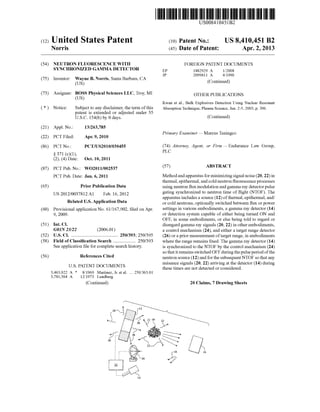
FIGS. 6A-C provide simpli?ed timing diagrams illustrat
ing in someWhat exaggerated fashion the manner in Which
gamma detector sWitching times may be functionally related
to target range as a result of the differing neutron velocities
Within a typical neutron cloud;
FIG. 7 shoWs a mobile application ofthe subject invention
used in connection With explosive detection; and
FIG. 8 is another exemplary application of the subject
invention for grading coal.
DETAILED DESCRIPTION OF THE PREFERRED
EMBODIMENT
Referring to the ?gures Wherein like numerals indicate like
or corresponding parts throughout the several vieWs, the pro
cess ofthermal neutron activation analysis (TNAA) is graphi
cally depicted in FIG. 1, Where a cloud or packet of thermal
neutrons 10 is emitted by a pulsed neutron source 12. That is
to say, the neutrons 10 are emitted in pulses, resulting in a
series of neutron clouds or packets 10, rather than as a con
tinuous stream. Conventional elements, such as housings,
mountings, supports, electrical poWer supplies, external
radiation shielding, etc. are omitted from the ?gures for clar
ity.
The neutron source 12 may be any suitable source for
creating an emission 10 of thermal, epithermal, or cold neu
trons, including but not limited to those examples provided in
the prior art references cited above. The neutron source 12
produces a pulsed neutron beam 10 by deliberately cycling
betWeen ON and OFF modes With a sWitch or sWitch-like
feature actuated by a control mechanism 24, described in
greater detail beloW. It should be understood that the actual
mechanism for poWering ON the neutron source 12 may
include adjusting and/or varying its neutron ?ux setting
Within a range ofeffective settings by any method. LikeWise,
poWering OFF or sWitching OFF the neutron source 12
betWeen pulses may include setting the source 12 to a very
loW neutron ?ux value rather than absolute Zero. In other
Words, the neutron source 12 is a sWitchable, i.e., pulsed,
neutron source capable of being sWitched betWeen different
poWer or ?ux levels, including but not limited to poWer set
tings OFF and ON, 10% and 90%, etc., and that the terms ON
and OFF may refer to “some effective level of neutron ?ux”
and “some non-effective neutron ?ux”, respectively.
12. US 8,410,451 B2
5
Cold, thermal, and epithermal neutrons 10 travel several
thousands of miles per hour. Gamma rays, by comparison,
travel at the speed oflight, more than 2/3 billionmiles perhour,
and hence travel thousands oftimes faster than the velocity of
cold, thermal, or epithermal neutrons. The relatively sloW
neutrons 10 move outWard from the neutron source 12. As
they do so, they produce gamma rays as they encounter most
kinds of atomic nuclei, such as the nuclei in the atoms in air.
The much faster gamma rays generated by the neutron inter
actions With nuclei in their paths are detected by a gamma ray
detector 14 nearly instantly after they are produced. Thus,
gamma rays that are produced immediately after a neutron
cloud leaves the neutron source arrive at the detector 14
signi?cantly earlier than those produced after the neutron
could has been traveling for some time. With the arrangement
of the neutron source 12 and the detector 14 as shoWn in the
diagram, this Would mean that the gamma rays produced at
locations close to the detector 14 arrive signi?cantly earlier
than those that are produced far from the detector 14. Since
the neutron pulse contains neutrons exhibiting a distribution
ofspeeds, the pulse spreads out as it travels, meaning that the
gamma rays generated at each distance arrive over time. This
is exempli?ed in FIG. 2, Where the population of thermal
neutrons 10 is shoWn arriving at a gamma ray detector as a
function of time, for a substance of interest in a target 16
located 11 meters from the neutron source 12, and for a 1
millisecond thermal neutron pulse. Note that epithermal neu
trons Would arrive more quickly than the thermal neutrons
upon Which FIG. 2 is predicated, and cold ones more sloWly,
based on their respective velocities/times of ?ight.
In general, in the context of interrogation procedures con
templated by this invention, a remote interrogation target 16
is located relatively far from the neutron source 12 and the
gamma ray detector 14, perhaps on the order of 10 to 20
meters for explosives detection operations and possibly
closer for other types of measurements. The target 16 is
interrogated With neutrons 10 to determine Whether it con
tains signi?cant levels ofa substance ofinterest. A substance
of interest may be any suitable element or compound that
produces measurable gamma rays in this application includ
ing, but not limited to, nitrogen-14 (14N), plutonium-239
(239Pu), uranium-235 (235U), chlorine, copper, aluminum,
boron, carbon orhydrogen in coal (forgrading purposes), and
the like.
When a substance of interest is dosed With neutrons 10,
gamma rays of interest 18 are produced in a process that has
been Well documented. In addition to these gamma rays of
interest 18, the neutrons 10 also produce unWanted or nui
sance gamma rays, including fratricidal gamma rays 20 and
backshine (also knoWn as sparkle) gamma rays 22. Fratricidal
gammas 20 are depicted in FIGS. 1 and 4A. Backshine
gamma rays 22 are a result of interactions With atoms of
atmospheric nitrogen-14. The phenomenon of atmospheric
nitrogen gamma ray backshine 22 is illustrated in FIGS. 3 and
4B. These nuisance gamma rays 20, 22 are generally pro
duced closer to the neutron source 12 and the gamma ray
detector 14 than are the gamma rays of interest 18. For this
reason, a suf?ciently short pulse of cold, thermal or epither
mal neutrons 10 Will cause gamma rays from the neutron
source (i.e., fratricidal gamma rays 20), from the illuminated
cone ofair (sparkle gamma rays 22) and from the substance of
interest (gamma rays ofinterest 18) to arrive at the detector 14
at successively later times. This is because the emitted neu
trons 10 arrive at the locations described at successively later
times. FIGS. 4A-C represent a sequence in Which a neutron
pulse or cloud 10 leaves a neutron source 12 headed for a
target 16 that is suspected to contain a substance of interest.
5
20
25
30
35
40
45
50
55
60
65
6
The cloud contains neutrons With a range of speeds distrib
uted around a mean value, Which corresponds to the “tem
perature” ofthe cloud. Although a cloud ofthermal neutrons
certainly has some very sloW components that Would qualify
as cold and some fast ones that Would qualify as epithermal,
those terms are generally used to describe the temperature of
the center of the velocity distribution, i.e., its characterized
velocity spectrum, and not the outliers ofa distribution. Thus,
the longitudinal spread ofneutrons 10 shoWn in FIGS. 4C and
5 is due to the velocity differences among the neutrons in the
cloud 10. Thermal neutrons, for example, With mean energy
of 4.05><10_21 Joules:0.026 eV, have velocities distributed
according to a Maxwell-Boltzmann distribution, With mean
velocity of 2,200 meters per second, corresponding to a
“room temperature” of 298.16 Kelvins and a momentum of
368x10‘24 kg-m/sec.
FIG. 4A shoWs the neutron pulse or cloud 10 leaving the
neutron source 12, and the source 12 itselfmaking fratricidal
gamma rays 20. The gamma ray detector 14 is not sensing
these nuisance gamma rays 20 during this time, because it has
not been turned to its ON mode by the control mechanism 24.
In FIG. 4B, the neutrons 10 are in ?ight toWard the target 16.
Backshine gamma rays 22 are created during this phase. Still
the gamma ray detector 14 remains in its OFF mode. FIG. 4C
shoWs the neutrons 10 producing gamma rays of interest 18
by colliding With a substance of interest contained in or
around the target 16. The gamma ray detector 14 is sWitched
to its ON mode by the control mechanism 24, and the gamma
ray detector 14 then detects these gamma rays of interest 18.
The gamma rays 18-22 generally travel very fastiat or near
the speed oflight. The only signi?cant quantities ofnuisance
gamma rays 20 and 22 reaching the detector 14 While it is
sWitched ON originate from the vicinity of the target itself,
rather than from the full collection ofpossible sources in the
environment, thus substantially reducing the problem of
noise in the gamma ray detector 14.
Ifthe approximate distance to the target 16 is knoWn, then
the duration ofa pulse ofneutrons 10 and the amount oftime
before the next pulse is generated canboth be tailoredto alloW
the gamma rays 18 from the substance of interest to arrive at
the gamma ray detector 14 during times When the smallest
number ofnuisance gamma rays 20, 22 are also arriving. The
result is a maximization ofthe signal-to-noise ratio (SNR).
The gamma ray detector 14 is sWitched ON or told to stop
disregarding the gamma rays by the control mechanism 24. A
calculation is made to determine the moment the bulk ofthe
neutrons 10 arrive at the target 16 based on the neutron time
of?ight (NTOF) and the extent to Whichthe cloud ofneutrons
has spread due to the spectrum ofneutron velocities Within it.
Distance betWeen the neutron source 12 and the target 16 is
determined by a target range detector 26. The gamma ray
detector 14 continues to sense the gamma rays of interest 18
for nominally the entire time the substance of interest in the
target 16 is being illuminated by substantial numbers ofneu
trons 10. During this time, the gamma rays of interest 18,
Which travel at the speed of light, are arriving at the gamma
ray detector 14. Connections betWeen the control mechanism
24, the neutron source 12, the gamma ray detector 14, and the
target range detector 26 are shoWn as broken lines.
The ?ux of neutrons emitted from the source 12 is con
trolled by commands from the control mechanism 24, Which
may comprise a computer running appropriate control soft
Ware. The connection betWeen the neutron source 12 and the
control mechanism 24 may be either unidirectional, in Which
commands pass from the control mechanism 24 to the neu
tron source 12, or bidirectional, in Which control and/or status
information pass in both directions betWeen the tWo compo
13. US 8,410,451 B2
7
nents. Between pulses, the neutron source 12 is either
switched OFF or else switched to a very low value. When the
neutron source 12 is either switched OFF or switched to a
very low neutron ?ux, the fratricidal gamma rays 20 either
cease entirely or drop to a very low ?ux.
The gamma ray detector 14 is designed to sense gamma
rays of interest 18. When in its ON mode, the detector will
also detects nuisance gamma rays 20 and 22, since it is impos
sible or impractical to design a detector that will selectively
reject all nuisance gamma rays. The detector 14 can be
switched ON and OFF by the control mechanism 24. Alter
natively, the detector 14 may instead be con?gured to remain
powered ON at all times but commanded by the control
mechanism 24 to regard or disregard (i.e., IGNORE) gamma
rays 18-22 at the respective times. This latter alternative is
intended within the meaning of ON and OFF modes of the
detector 14. The connection between the gamma ray detector
14 and the control mechanism 24 may be either unidirec
tional, in which commands pass from the control mechanism
24 to the gamma ray detector 14, or bidirectional, in which
control and/or status information pass in both directions
between the two components.
The control mechanism 24 sends commands to both the
neutron source 12 and the gamma ray detector 14. In the case
ofthe neutron source 12, these commands may specify a level
ofneutron ?ux emitted. In the case ofthe gamma ray detector
14, these commands may specify the state ofthat component
regarding either its ON/OFF state or its regarding or IGNOR
ING of gamma rays, depending on the embodiment. In addi
tion, other commands may be issued, such as system com
mands, self-test, diagnostic, etc. In addition to commands
being sent by the control mechanism 24, optionally, status
information may be sent from either the neutron source 12 or
the gamma ray detector 14, or both. Such status information
may either be sent upon request ofthe control mechanism 24
or autonomously by either or both of the neutron source 12
and the gamma ray detector 14. The control mechanism 24 is
preferably a computer controlled device ofthe type commer
cially available and readily adapted for use in this invention
by those of skill in the art.
In one embodiment, the control mechanism 24 receives
encoded information that includes the distance to the target 16
as reported by the target range detector 26, the total gamma
ray ?ux detected by the gamma ray detector 14 and the num
ber ofneutrons per second emitted by the neutron source 12.
In one embodiment, the control mechanism 24 uses this
encoded information to de?ne a time cycle over which the
neutron source 12 and the gamma ray detector 24 each com
pletes a respective ON cycle and an OFF cycle. The control
mechanism 24 further de?nes the percentage of said time
cycle that the neutron source 12 is ON (i.e., the neutron source
“duty cycle”), the percentage of said time cycle that the
gamma ray detector 14 is ON (i.e., the gamma ray detector
“duty cycle”), and the delay time between when the neutron
source turns ON and the gamma ray detector turns ON. As
will be apparent to one skilled in the art, the duty cycles will
generally be different for the neutron source 12 than for the
gamma ray detector 14, since, on the one hand, the neutron
source 12 works with comparatively slow nuclear particles,
and on the other hand, the gamma ray detector 14 works with
gamma rays traveling at the speed of light.
The target range detector 26 measures the distance
between the neutron source 12 and the substance of interest
16 and makes such determinations available to the control
mechanism 24 either upon query by the control mechanism
24, on a schedule determined by the operating parameters, or
continuously. An optional imaging sensor (e.g., a video cam
5
20
25
30
35
40
45
50
55
65
8
era or its functional equivalent) may be paired with the target
range detector 26. The optional imaging sensor and the target
range detector 26 collect and transmit range and image data to
the control mechanism 24. The target range detector 26 is
effective to detect the range from the neutron source 12 to the
target 16, and may be of the electromagnetic wave type,
optical type, sonic type, acoustic type, or a hybrid system
based on one or more single-modality-systems. By knowing
the speed, or average speed, of the neutron cloud 10 and the
distance to the target 16, the NTOF can be computed.
Referring now to the time-based chart of FIG. 5, a theo
retical example is provided in which a beam ofthermal neu
trons 10 with an average speed of 2,200 meters per second is
aimed at a target 16 containing a substance ofinterest located
approximately 11 meters away from the source 12. In this
example, the neutrons 10 are sent out in a pulsed beam that is
turned ON for l millisecond and OFF for 5 milliseconds.
Further, in this example, the gamma ray detector 14 is turned
OFF for 3 milliseconds and then ON for 3 milliseconds. This
pattern may be repeated every 6 milliseconds. (The distance
of 11 meters here chosen to result in round numbers for this
illustrative example.) As depicted in this Figure, the neutrons
spread within the cloud 10 due to their differing velocities.
The faster neutrons naturally reach the target 16 earlier than
the slower moving neutrons. As a result, it is foreseeable that
at most extended ranges, the ON (i.e., pulse) time of the
gamma detector 14 will exceed the ON (pulse) time of the
neutron source 12.
More speci?cally, the neutrons 10 in any given pulse (here
shown as a l-millisecond pulse) have a spectrum of energies
distributed according to a Maxwell-Boltzmann distribution,
with mean energy of 0.027 electron volts, corresponding to a
speed of about 2,200 meters per second. As the “cloud” of
neutrons produced during this pulse moves away from the
source 12 and detector 14, it spreads out in the direction of
travel, with the faster neutrons’ moving ahead ofthe cloud’s
center and the slower ones’ falling further behind the cloud’ s
center. In FIG. 5, the faster neutrons are shown as solid black
circles and the slower moving neutrons with cross-hatching.
Only two neutron speeds (fast and slow) are shown here for
convenience, it being understood that in the typical neutron
cloud 10 there will likely be a dispersion ofvelocities. By the
time the cloud 10 arrives at the target 16 (l 1 meters away from
the source 12), it is somewhat stretched or longer in the
direction oftravel than it was when it was emitted, due to the
range of neutron velocities in the cloud 10.
FIGS. 6A-C shows, in generaliZed fashion, the manner in
which the gamma ray detector 14 switching times are prefer
ably altered by the control mechanism 24, on the ?y, as a
function of target range. FIG. 6A represents a situation in
which the substance of interest 16 is relatively close (Range
“X”) to the neutron source 12, and as a result the differing
neutron velocities within the cloud 10 do not result in a
signi?cant degree of longitudinal spread. The gamma ray
detector 14 is gated ON for a time equal to the duration ofthe
neutron source pulse plus an additional calculated time to
account forthe longitudinal spreading ofthe neutron cloud 10
due to the distribution ofvelocities within it, and correspond
ing to the distribution ofneutron arrival times at the target 16.
In FIG. 6B, the range (Y) is greater than that of FIG. 6A,
resulting in the fact that the arrival times of the respective
fastest and slowest neutrons in the neutron cloud 10 are more
longitudinally (and temporally) dispersed. The interval
between gating of the neutron source 12 ON is thus longer
(i.e, lower frequency pulsing), due to the increased travel
times of the neutrons to a more distant substance of interest
16. In FIG. 6C, the range to target 16 is further still, causing
14. US 8,410,451 B2
an even more noticeable spread in the time during Which
gamma rays of interest 18 can be expected to arrive at the
detector 14. Thus, the gamma ray detector 14 can be con
strained in its OFF condition beginning With the initiation of
the neutron source pulse plus a time delay generally equal to
the range divided by the speed of the fastest foreseeable
neutrons in the cloud 10 (i.e., the fastest reasonable NTOF).
The gamma ray detector 14 is then sWitched ON, and main
tained in this ON condition for a period of time generally
equal to the neutron source pulse duration plus the time of
?ight for the bulk of the neutrons in the cloud 10. In other
Words, the gamma ray detector 14 is constrained in its OFF
mode at the initiation ofthe neutron source pulse period plus
a time delay generally equal to the neutron source pulse
duration plus the fastest reasonable NTOF plus an additional
time period generally equal to the time difference betWeenthe
fastest reasonable NTOF and the sloWest reasonable NTOF.
In this example, fratricidal gammas 20 are produced by the
neutron source 12 during the l millisecond length of the
pulse. These fratricidal gammas 20 arrive at the gamma ray
detector 14 virtually instantaneously, as they are produced
before the neutrons 10 even leave the generator 12. HoWever,
these fratricidal gamma rays 20 are not reported by the
gamma ray detector 14 because it is in the OFF mode When
they arrive. Atmospheric backshine gamma rays 22 are pro
duced as the cloud of neutrons 10 moves through the air
toWard the target 16. These backshine gamma rays 22 are also
not reported by the gamma ray detector 14, since it is shut
OFF for the ?rst several milliseconds of the 6-millisecond
total cycle.
As can be seen in FIG. 2, due to the broadening ofthe pulse
ofthermal neutrons due to the velocity spectrum, the leading
edge of the cloud’s center arrives at the target 16 approxi
mately 3 milliseconds after leaving the source 12 (time
required to cover the hypothetical 11 meter spacing). The
trailing edge ofthe cloud’s center arrives 2 milliseconds later,
or approximately ?ve milliseconds after leaving the source
12. Although some neutrons 10 arrive both prior to and after
this 2-millisecond “time WindoW”, the majority of neutrons
10 arrive during the WindoW, as shoWn illustratively in both
FIGS. 5 and 6.
The gamma ray detector 14 is sWitched ON during the
3-to-5 millisecond time WindoW. Gamma rays 18 produced in
the region ofthe target 16 arrive at the gamma ray detector 14
virtually instantaneously and are reported by the gamma ray
detector 14. The proposed strategy minimiZes the total num
ber of gamma rays from sources other than the substance of
interest that are reported by the gamma ray detector 14, thus
maximiZing SNR.
In real-World experience, as opposed to theoretical
examples such as that given above, it may be necessary to
adjust the pulses and ON/OFF cycle of both the neutron
source 12 and/or the gamma ray detector 14 in order to maxi
miZe SNR in the face of the spreading neutron cloud 10,
neutron cloud divergence, the thickness of the area being
inspected, and other concerns. HoWever, laboratory experi
ments have demonstrated that the differences betWeen theo
retical predictions of the best pulse timing and empirical
results may be acceptably small. The time constants involved
(mean neutron speed on the order of 0.455 milliseconds per
meter), the distances involved (up to about 20 meters), and the
pulsing rate (on the order of 167 hertZ With 67% dead-time)
are all reasonable and achievable for most contemplated
applications.
In other disciplines, such as radar and sonar, the synchro
niZation of a detector With modulations in the strength of an
interrogation signal is referred to as “pulse gating”. That
5
20
25
30
35
40
45
50
55
60
65
10
terminology is borroWed and applied here to the case of
neutron analysis to underscore analytical and theoretical
similarities With other detection modalities. HoWever, neu
tron pulse gating differs from pulse gating in radar and sonar
in several important Ways, notably that, With these tWo sens
ing modalities, the interrogating signal and the return signal
are of the same type, Whereas With neutrons, they are very
different, travel at very different speeds, and require different
detection schemes.
Embodiments of the present invention include systems in
Which the neutron source 12 is pulsed, systems in Which the
gamma ray detector 14 is optionally time gated so as to
literally not respond to gamma rays While the neutron ?ux is
too high or the substance of interest is not being illuminated,
and systems in Which the gamma ray detector 14 is instructed
to ignore the nuisance signals, despite the fact that it is physi
cally sensing them.
FIGS. 7 and 8 illustrate exemplary applications of the
subjectmethods and apparatus for detecting remote explosive
substances (FIG. 7) in mobile applications and for grading
coal (FIG. 8) as it moves along a conveyor belt. These are
offered merely by Way of example, and it is to be understood
that many other applications of this technology are contem
plated and Will fall Within the scope of the claims.
EXAMPLE
As a further example of one possible embodiment of the
invention, one may consider a control mechanism 24 that
includes a computer With a means ofgenerating several chan
nels of digital electronic pulses such as TTL (Transistor
Transistor Logic) pulse train generators, a collimated pulsed
neutron source 12, a range-?nding device 26 such as a
RADAR or LIDAR gun directed along the path of the colli
mated neutron pulses, and a gamma ray detector 14 Whose
data acquisition can be gated ON or OFF by a digital elec
tronic pulse. Inthis example, the computer (incorporated into
or operated in conjunction With the control mechanism 24)
may include a means of moving/controlling the pointing
direction of the collimator on the neutron source 12 and the
pointing direction ofthe range-?nding device 26.
Continuing in this example, the computer aims the colli
mated neutron source 12 in a particular direction ofinterest or
causes it to scan across a particular ?eld ofvieW, While direct
ing the range-?nding device 26 to simultaneously track along
the same direction of vieW as the collimated neutron source
12. Every 100 milliseconds (for example) the computer que
ries the range-?nding device 26 and records the distance in
meters to the nearest solid object 16 in the neutron beam path
10. In response to this range data, the computer immediately
directs its electronic pulse generators to adjust their pulse
train patterns according to one or more straightforward
instruction sets. Since the typical travel rate forthe centroid of
a pulse of thermal neutrons 10 is nearly 2200 meters per
second, a reasonable set of instructions to the pulse train
generators might appear as folloWs:
Instruction Set (1)
Set t1:0.2><(D/2200 meter per sec),
Set t2:l .0><(D/2200 meter per sec),
Set t3:0.6><(D/2200 meter per sec),
Set t4:0.6><(D/2200 meter per sec),
Where:
D is the distance to the solid object in meters, and
t1, t2, t3, t4 are time intervals.
Generate a pulse trainthat Will pulse the neutron source ON
for duration t1, then OFF for durationt2, thenrepeat this pulse
cycle for a duration of 100 milliseconds.
15. US 8,410,451 B2
11
Generate a second pulse train, synchronized With the ?rst
pulse train, that Will gate the gamma ray detector OFF for
duration t3, then ON for duration t4, then repeat this pulse
cycle for a duration of 100 milliseconds.
Instruction Set (2)
Every 100 milliseconds, repeat the control operation as
folloWs:
Update the motion control instructions that steer the neu
tron source 12 and range-?nder 26.
Query the range-?nder 26 to ?nd the distance to the ?rst
solid object 16 in the neutron path.
Recompute the neutron source 12 and gamma ray detector
14 time intervals and reset the pulse trains as indicated in
Instruction Set (1) above.
The effect of these instructions, for example, When an
object 16 is in vieW at range 1 1 meters, Will be to turn on the
neutron source for l millisecond, then turn off the neutron
source for 5 milliseconds While the majority of the thermal
neutrons pass into and through the object at range 11 meters.
The gamma ray detector 14 is gated OFF during the ?rst 3
milliseconds, Which includes both the period When the neu
tron source is on and the period While a majority of the
thermal neutrons have not yet reached the target range of 11
meters. Then the gamma ray detector is gated ON during the
next 3 milliseconds, Which includes the period of time When
most of the neutrons Will pass into and through the object at
target range 1 1 meters. In this Way, the gamma ray detector 14
Will record far feWer nuisance gamma rays 20, 22 from the
neutron source 12 and nearby air relative to the number of
useful gamma rays 18 detected from the target range at 11
meters. As the target range changes from moment to moment
When the ?eld ofvieW changes, the computer Will update the
gating every 100 milliseconds or so to maintain a nearly
optimal signal-to-background ratio in this manner.
It should be clear to those practiced in the art that other
embodiments of this invention could use any suitable auto
mated directional range-?nding technique in place of the
LIDAR or RADAR; that any set of appropriate formulas/
instructions could replace those in Instruction Set (1) to opti
mize the signal-to-background ratio for a variety of different
source/detector geometries and for neutrons With velocity
distributions both faster and sloWer than thermal neutrons on
average; thatthe update interval forthe range-?nderandpulse
trains could be set to any suitable interval other than 100
milliseconds; that the synchronized digital pulse generators
could be replaced With any equivalently functional mecha
nism to communicate a duty cycle or ratio ofON/OFF periods
or similarly useful timing information to the synchronized
time-gated neutron source and gamma ray detector; and that
the collimated neutron source and range-?nder could be ?xed
in a single orientation or could be controlled by the computer
or by a live operator in pointing at different targets ofinterest
or ?elds of vieW.
Thus, the invention relates generally to the use of ?ux
modulation or “pulsing” of a neutron source 12 capable of
emitting thermal, epithermal, and/or cold neutrons 10, as Well
as time-gating the gamma ray detector 14 in synchronization
With the time of ?ight of a packet or cloud ofneutrons 10, as
a means to minimize signal noise, under the control of the
control mechanism 24. The invention improves upon prior art
techniques by pulsing the neutron beam 10 in such a Way so
as to improve the signal-to-noise ratio (SNR), by gating the
gamma ray detector 14 in synchronization, and by the use of
a control mechanism 24 to coordinate both systems. One
result of pulsing the neutron beam 10 is that, during the
pulses, the neutron ?ux varies from high to loW. The neutrons
10 stimulate, or produce, the gamma rays 18-22, including
20
25
30
35
40
45
50
55
60
65
12
both gamma rays of interest 18 and also fratricidal 20 and
other nuisance gamma rays 22 from areas other than the target
area 16 being inspected. During times When loW neutron ?ux
arrives at any particular location, the production ofall types of
gamma rays from such location 18-22, including both those
that are interesting 18 and those that are noise 20, 22, is
minimized. If the gamma ray detector 14 is commanded by
the control mechanism 24 to ignore gamma rays 20, 22 arriv
ing at times other than those during Which gammas ofinterest
18 are physically able to arrive, then the SNR is improved.
The foregoing invention has been described in accordance
Withthe relevant legal standards, thus the description is exem
plary rather than limiting in nature. Variations and modi?ca
tions to the disclosed embodiment may become apparent to
those skilled in the art and fall Within the scope ofthe inven
tion.
What is claimed is:
1. A method for interrogating a remote target (16) With
sloW neutrons (10) to produce gamma ray ?uorescence from
targets that contain at least one speci?ed substance ofinterest,
said method comprising the steps of:
providing a remotely located target (16);
providing a sloW neutron source (12) capable ofgenerating
at least one of thermal, epithermal, and cold neutrons,
the neutron source (12) having poWer ON and OFF
modes, the neutron source (12) operable in its ON mode
to emit neutrons (10) capable oftraveling over time and
distance to reach the target (16) and there produce
gamma rays of interest (18) upon interaction With a
substance of interest, the travel time ofthe emitted neu
trons (10) to the target (16) de?ning a neutron time of
?ight (NTOF);
providing a gamma ray detector (14) proximate the neutron
source (12), the gamma ray detector (14) having poWer
ON and OFF modes and operable in its ON mode to
detect gamma ray signals (18-22);
poWering ONthe neutron source (12) for a pulse period and
then poWering OFF the neutron source (12); and
constraining the gamma ray detector (14) in its OFF mode
during the pulse period and for an immediately subse
quent additional period of time generally equal to the
NTOF, and then poWering ON the gamma ray detector
(14), Whereby any unWanted nuisance gamma signals
(20, 22) arriving at the detector (14) during the pulse
period and during the subsequent NTOF period are not
detected.
2. The method ofclaim 1, further including maintaining the
neutron source (12) in its OFF mode While the gamma ray
detector (14) is in its ON mode.
3. Themethod ofclaim 1, furtherincluding determining the
distance betWeen the neutron source (12) and the target (16)
prior to said step of poWering ON the gamma ray detector
(14).
4. The method ofclaim 3 Wherein the neutrons (10) emitted
by the neutron source (12) have a Characterized velocity
spectrum, and further including the step of calculating the
NTOF as a function ofthe neutron velocity.
5. The method ofclaim 3 Wherein said step ofdetermining
the distance betWeenthe neutron source (2) andthe target (16)
includes measuring electromagnetic radiation ?oW the target.
6. The method ofclaim 3 Wherein said step ofdetermining
the distance betWeen the neutron source (12) and the target
(16) includes monitoring of the re?ection of acoustic Waves
from the target (16).
7. The method ofclaim 3 Wherein said step ofdetermining
the distance betWeen the neutron source (12) and the target
(16) includes optical sensing.
16. US 8,410,451 B2
13
8. The method of claim 3 said step of determining the
distance betWeen the neutron source (12) and the target (16)
includes at least one of infrared, terahertz, and millimeter
Wave techniques to determine range.
9. The method of claim 1, Wherein said step of powering
ON the gamma ray detector (14) occurs for a period of time
generally equal to the pulse period of the neutrons and then
poWering OFF the gamma ray detector (14).
10. The method ofclaim 6, further including repeating said
step ofpoWering ON the neutron source (12) after said step of
poWering OFF the gamma ray detector (14).
11. The method ofclaim 1, Wherein the neutron source (12)
has a ?ux setting, and said step of poWering ON the neutron
source (12) includes varying the neutron ?ux setting.
12. The method of claim 1 Wherein said step of poWering
OFF the gamma ray detector (14) includes IGNORING
gamma rays (18-22) from all sources.
13. The method of claim 1 further including the step of
providing a control mechanism (24) operatively associated
With the neutron source and the gamma ray detector (14) for
independently sWitching neutron source (12) and the gamma
ray detector (14) betWeen the respective ON and OFF modes.
14. The method ofclaim 1 Wherein the neutrons (10) emit
ted by the neutron source (12) have a velocity spectrum that
may be characterized by a fastest reasonable neutron velocity
and a sloWest reasonable neutron velocity, and Wherein said
step of constraining the gamma ray detector (14) in its OFF
mode includes constraining, the gamma ray detector (14) to
its OFF mode at the initiation of the neutron source pulse
period plus a time delay generally equal to the neutron source
pulse duration plus the fastest reasonable NTOF plus an addi
tional time period generally equal to the time difference
betWeen the fastest reasonable NTOF and the sloWest reason
able NTOF.
15. A method for interrogating a remote target (16) With
sloW neutrons (10) to produce gamma ray ?uorescence from
targets that contain at least one speci?ed substance ofinterest,
said method comprising the steps of:
providing a remotely located target (16);
providing a sloW neutron source (12) capable ofgenerating
at least one of thermal, epithermal, and cold neutrons,
the neutron source (12) having poWer ON and OFF
modes, the neutron source (12) operable in its ON mode
to emit neutrons (10) traveling at a spectrum of veloci
ties over time and distance to reach the target (16) and
there to produce gamma rays (18) upon interaction With
a substance of interest, the travel time of the emitted
neutrons (10) to the target (16) de?ning a neutron time of
?ight (NTOF), the characterized velocity spectrum
including a fastest reasonable neutron velocity and a
sloWest reasonable neutron velocity;
providing a gamma ray detector (14) proximate the neutron
source (12), the gamma ray detector (14) having poWer
ON and OFF modes and operable in its ON mode to
detect gamma ray signals (18-22);
providing a control mechanism (24) operative to selec
tively sWitch the neutron source (12) betWeen its poWer
ON and OFF modes and to independently sWitch the
gamma ray detector (14) betWeen its poWer ON and OFF
modes;
poWering ON the neutron source (12) via the control
mechanism (24) for a pulse period and then poWering
OFF the neutron source (12);
constraining the gamma ray detector (14) in its OFF mode
via the control mechanism (24) at the initiation of the
20
25
30
35
40
50
55
60
14
neutron source pulse period plus a time delay generally
equal to the neutron source pulse duration plus the fast
est reasonable NTOF plus an additional time period,
generally equal to the time difference betWeen the fastest
reasonable NTOF and the sloWest reasonable NTOF;
and then poWering ON the gamma ray detector (14) via
the control mechanism (24); maintaining the neutron
source (12) in its OFF mode via, the control mechanism
(24) While the gamma ray detector (14) is in its ON
mode;
determining the distance betWeen the neutron source (12)
and the remote target (16) prior to said step ofpoWering
ON the gamma ray detector (14) and
repeating said step of poWering ON the neutron source
after said step ofpoWering OFF the gamma ray detector
(14).
16.An apparatus for interrogating a remote target (16) With
sloW neutrons (10) to produce gamma ray ?uorescence When
the target (16) contains at least one speci?ed substance of
interest, said apparatus comprising:
a sloW neutron source (12) capable of producing at least
one ofthermal, epithermal, and cold neutrons, said neu
tron source (12) having ON and OFF modes and oper
able in said ON mode to emit neutrons (10) capable of
producing gamma rays (18) upon interaction With a sub
stance ofinterest, the travel time ofthe emitted neutrons
(10) to the target (16) de?ning a neutron time of ?ight
(NTOP);
the emitted neutrons (10) having a velocity spectrum char
acterized by a fastest reasonable neutron velocity and a
sloWest reasonable neutron velocity;
a gamma ray detector (14) con?gured to recognize gamma
ray signals (18-22), said detector (14) having ON and
OFF modes and operable in said ON mode to detect
gamma rays (18-22);
a target range detector (26) con?gured to calculate the
distance betWeen the neutron source (12) and the remote
target (16);
a control mechanism (24) operatively interconnecting said
neutron source (12), said gamma ray detector (14) and
said target range detector (26), said control mechanism
(24) operable to poWer ON said neutron source (12) for
a pulse period then poWer OFF the neutron source (12)
While constraining said gamma ray detector (14) in its
OFF mode for a period of time generally equal to said
neutron source’ s pulse period plus the fastest reasonable
NTOF plus an additional time period generally equal to
the time difference betWeen the fastest reasonable
NTOF and the sloWest reasonable NTOF and then
immediately poWering ON the gamma ray detector (14).
17. An apparatus according to claim 16, Wherein said target
range detector (26) includes at least one of a RADAR and
LIDAR device.
18. An apparatus according to claim 16, Wherein said neu
tron source (12) includes a collimated pulsed neutron source
(12).
19. An apparatus according to claim 16, Wherein said neu
tron source (12) includes a directionally aimable pulsed neu
tron source (12).
20.An apparatus according to claim 19, Wherein said target
range detector (26) includes a directionally aimable target
range detector (26), and Wherein said control mechanism (24)
is operable to synchronize direction movements of said range
detector (26) and said pulsed neutron source (12).
* * * * *