1. Thermal Load Calculations and
Sizing of Equipment.
Study of initial Architectural Drawings in
order to design the best suitable VAC
systems to the project and to identify
interferences.
Exploration of opportunities to be suggested to the Architects
for reduction of AC loads aiming (substantial all lifetime) savings
in first costs and in demand of electrical energy for the Client.
Issuing of first set of drawings
for meetings on new changes
and solution of interferences.
Execution of changes and issue
of 2nd set of drawings.
Technical analysis of
proposals of VAC contractors
(only abroad).
Inspections of installation work with
eventual approval of requested
changes by the contractor for
inclusion in his As Built drawings.
Start up of systems
Approval of
installations
1
10
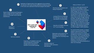
Notes on Points 5 up 10
In order to satisfy high demands for
fast execution of designs in Israel,
aiming fast erection of the enterprise,
while changes are still occurring in
Architectural drawings, pressure for
issuing Point 6 is already being made
while Point 5 is still under way. Over this
reason there are the changes imposed
by Safety, by Lighting, by Electrical, by
Communication and by Data Systems,
so, the labels ‘For Execution’ on VAC
drawings have no choice but to happen
later, after many revisions of drawings.
Changes on VAC drawings impose in
turn also changes in other disciplines.
For control of this situation, an always
updated superposition analysis of the
systems and an up-to-the–minute
management of project are imperative
for its success. This is normally done by
third companies providing on-line the
status of last revisions of drawings.
However, is not that rare to find
Contractors in the field working with an
older set of drawings.
2 3
4
5
Elaboration and issuing of List of
Materials, Cost Estimate and
Specifications for mounting of the
systems.
6
7
8
9
2. A- Chilled Water Systems
Those equipment are not used in Israel
once almost all Condensers of Chillers
are air cooled.
Notes:
1- Cold water piping between Chiller and
AHU (Air Handling Units) is not shown in
this picture.
2- Israeli Normative 1001 forbids air
return by plenum, purposely to avoid
the scattering of smoke in case of fire.
Israeli Architects don’t like the Classical
and International design with larger
AHU inside Machine Rooms (mainly for
VAV control strategy). Architects want
full floor area for their designs. They are
who choose the Consultants and are the
Project Manager. As result, 35-40cm
height AHU are normally designed for
installation inside voids of acoustic
ceilings of each room. That means 2
electrical connections, 3 pipe
connections and 1 fresh air connection
for each AHU of each room. Further
important cost implications of that
Normative are: 1- buildings need to be
taller once voids of acoustic ceilings
must be higher in order to
3- Cold Water Systems for buildings
have an average cost of U$ 5000 per
TR (Ton of Refrigeration) abroad and
an average lifetime between 15 and
20 years when properly maintained.
Chillers are usually imported from
Europe here in order to get assured
their long lifetimes with lower prices
as possible, despite local
manufacturers. One TR can condition
a floor area between 10 and 18
square meters.
Cost of such system in Israel can reach
U$ 8000 per TR, for the appointed
reasons and because of taxes.
Cooling only systems are the
preferred with the heating for
wintertime done by electric
resistances inside the AHU.
Differently, Natun Design and
Consulting applies Heat Pump
Systems with hot water produced by
the Chillers as source of heat (2
pipes). Also, our designs include 3 way
valves wholly and not a mix of 2 way
valves and 3 way valves. We are sure
that this kind of saving is not in favor
of quality of the thermal comfort to
be achieved and not in favor of
Clients’ interest, once he already faces
so many controversial higher costs.
accommodate those high units with the interferences of several systems always
around them in those voids. 2- disturbances inside workplaces for activities of
maintenance become inevitable. 3- risks of generation and propagation of noises from
AHU are higher. 4- installation works are slower. 5- when outside air is not available by
piers, the impact over Architectural designs to provide an outside air connection for
each user of each floor is heavy and usually not esthetic for the building.
3. B- VRF Systems
Variable Refrigerant Flow Systems are less costly than Cold Water Systems, however,
should not be designed as the sole solution for large or very tall buildings. The reason
is that the condensers of VRF systems demand a quite large total installation area,
usually of the roof and normally there is not enough space there for all of them.
Natun Design and Consulting applies for considerable large/tall buildings a dual
strategy: Cold Water System for the internal areas of the building, which represents a
quite constant load during all year, together with VRF systems for the peripheral area.
Normally 1 or 2 piers are needed for each façade, in order to stay below the total
piping length limit of VRF manufacturers.
Once the solar radiation does not hit all the façades at the same time, there is an
opportunity to retrieve heat from one side of the building to the opposite one, during
summer and also during the winter. Heat Recovery VRF systems are designed for
peripheral areas by us with great success and providing a substantial reduction on
electricity bills for the Clients.
VRF units are low-medium capacity and designed to be installed inside voids of
acoustical ceilings. They are 30cm high or less. There is also the Wall type units, which
can work together with the Ceiling type.
Installation of VRF units in basements of buildings is not a problem once the units are
equipped with small pumps for draning of condensate water.
Picture on this page shows a Heat Recovery System for a small house, with the
condenser over the ground. At same time the sleeping room of 1st floor is being
conditioned with cool air, the floor of ground floor is being heated and also hot water
for kitchen and showers is provided.
4. C- Package Units
Natun Design and Consulting incorporates air cooled package units with following considerations:
1- Unit must be positioned in an external area, where axial blowers pull the air through the
condensers and expel it upwards.
2- Noise produced by blowers can disturb neighbors, mainly if they operate at night.
3- System comprises 2 thermal insulated ducts, one for supply and one for return to be
connected to the unit.
4- To reach the room(s) to be conditioned, those ducts must penetrate wall(s) or concrete slab(s).
4a- Roof Top is an alternative unit installed over a rectangular hole previously done through the
concrete slab. Both ducts are connected underneath the unit.
4b- If piers were considered during construction plans, so insulated ducts can be
installed inside those piers. See detail and item 4d.
4c- For packages supplying conditioned outside air, there is only the supply duct
to cross walls, concrete slabs or piers to reach the rooms.
4d- As alternative, for piers internally insulated with jet-sprayed polyurethane at
least 1” thick, the duct(s) can end close the beginning of the curve shown in the
detail.
5. Chillers in Cold Water Systems
D- Further Comparisons Between the Systems
1- Can be Refrigeration Only, Heat Pump or Heat Recovery types (with max water
temperature of 60֯C, in general).
2- Can be Noise, Low Noise and Very Low Noise types.
3- Save energy by staggering compressors (reciprocating type) or by reduction of flow
of gas (centrifuge and screw types).
4- Need external controls for saving energy through reduction of water flow by pumps
or through bypass of water flow from outlet to inlet.
5- Cost more if for operating as Heat Pumps, especially for Low External Air
Temperatures, and even more if are Heat Recovery type.
6- Loss of 1 compressor can compromise its capacity between 25% and 50%
(reciprocating type) and 50% to 100% (screw and centrifugal types).
7- Need small cross area of piers for the water tubes, supports and tees. Not too
differently of VRF systems, neglecting the strategy of piers’ positioning.
8- Are heavy.
9- Have a Thermal Loop effect (cold water inside the tubes), usually enough for a fast
start up of a Diesel Generator, dispensing the use of Storage Tanks.
10- Are still vertical limited for lifting by cranes (2016).
11- Main parts, except Expansion Valves and blowers, not easily replaceable.
12- Are equipped with Complete Electric Boards for power and control, but need an external one for the main switch.
13- Blowers of Condensers are normally constant rotation type.
14- Capture and sending of analogic and/or digital data from chiller’s microprocessor to stations of operators for warning and information are usually not
possible. The reasons are for quality control and warranty purposes. Just a very few manufacturers of chillers make available an open protocol for
communication with operators. Normally, operation data is collected by separate sensors installed by contractors. Signals of those sensors are then sent by
wire to microprocessors of Client installed till 300m far away, reaching the stations of operators anywhere.
6. VRF Systems
8- Are not vertical limited for lifting once can be transported by escalators or stairs.
9- Main parts are easily replaceable.
10- Are equipped with Complete Electric Boards for each condenser unit but need
an external one for the main switch.
11- Motor of blower of Condenser are normally Variable Speed Drive.
12- Are not noisy.
13- Sending of analogic and/or digital data to operators is possible from microprocessor boxes
of VRF manufacturers. Boxes can be connected by wire till 300m far from condensers and from
them electronic signals are sent to operators’ displays anywhere. Microprocessors are limited,
however, to number of condensers and floor control boxes they are able to manage.
14- Need piers for interconnections of 2 or 3 copper tubes from each control box at each floor,
with the condensers. There can have several control boxes at each floor and so piers for VRF
systems should be distributed in order to not let them be centralized and big too much. This pier
distribution also makes possible reductions of the total length of copper tubes to be installed.
Total length of copper lines is limited by each VRF manufacturer to be not more than 300m.
15- Tailor Made Condensing Units (Package type), by a third part
• Are only able to save energy if compressors are Inverter type or Screw type.
• Condenser blowers are usually constant rotation type.
• Need electronic expansion valves from VRF manufacturers for control and
communication reasons.
• Loss of 1 compressor impacts between 25% and 50% the system capacity.
• Total cost per TR can be lower than for integral VRF systems.
• Solution permits the use of a smaller area of roof.
• Lifetime expectancy of system falls.
• Condenser coils have to be well designed and thermodynamically balanced with VRF
components if system is intended to work properly, mainly if operating as Heat Pump
or as Heat Recovery types.
• Limitation of vertical lifting is the same as for Package Units.
VRF Systems (see limitations for VRF systems operating with Tailor Made
Condensing Units, built by a third part, on item 15)
1- Life expectancy of 15 years, well maintained.
2- Save energy by reducing compressor rotation and so the flow of refrigerant gas.
3- When chosen as Heat Pump type, are normally factory designed to operate
under Low External Air Temperatures.
4- Are more costly if Heat Recovery type, what turns necessary a thermal design
strategy.
5- Loss of 1 compressor doesn’t compromise significantly the whole system
capacity.
6- Only can present a Thermal Loop characteristic if Heat Recovery type.
7- Are not heavy.
Further Comparisons Between the Systems
7. Package Units
1- Life expectancy between 12 to 15 years when well maintained.
2- Cost around U$ 2000 per TR, depending on kind and number of compressors
as well the kind of system (Cooling Only or Heat Pump).
3- If Tailor Made type, must be designed with the compromise of
Thermodynamic Balance between components, in order the unit to provide
expected capacities in Summer and Winter.
4- Save energy by staggering compressors (reciprocating type) or by reducing
flow of gas (Screw or Inverter types).
5- Cost even more if for operating as Heating Pumps at Low External Air
Temperatures.
6- Loss of 1 compressor can compromise between 25% and 50% of unit capacity.
7- Need big crossing areas for ducts through piers or walls, as already mentioned.
8- Don`t present Thermal Loop capability.
9- Are less heavy than Chillers but heavier per TR than VRF.
10- Are vertical limited for lifting by cranes (2016).
11- Main parts, except Expansion Valves and Condenser Blowers, not easily
replaceable.
12- When Tailor Made type, can be equipped with Complete Electric Boards for
power and control, but normally an external one for the main switch is necessary.
13- Axial blowers of Condensers are normally constant rotation. If centrifugal fans
are applied (Tailor Made type), their motors can be VSD.
14- Can generate more noise than Chillers or VRF systems do.
15- Tailor Made Condenser units can operate for VRF systems by incorporating
Electronic Expansion Valves, however, energy savings will be achieved if
compressors are variable speed, as mentioned in previous item.
D- Further Comparisons Between the Systems
In the picture a Roof Top Unit to be installed over a previously planned rectangular
hole in concrete slab. Supply and return ducts are connected underneath the unit.
At the left side of it, two openings for inlet of external air for the conditioned
spaces.
8. COP and EER
Energy Efficiency Ratio (EER) and Coefficient of Performance (COP) of a cooling unit are
determined by the output cooling divided by the electrical power input used to achieve it. The
difference is that for calculation of EER there is a defined set of outside air temperatures, a set
of inside air temperatures and a room relative humidity of 50%.
In the set, each external air temperature is related to a thermal capacity of the unit, as follows:
Test Condition
"A" = 100% Capacity @ 95˚ FDB Test Condition
"B" = 75% Capacity @ 81.5˚ FDB Test Condition
"C" = 50% Capacity @ 68˚ FDB Test Condition
"D" = 25% Capacity @ 65˚ FDB
IEER = 0.02A + 0.617B + 0.238C + 0.125D
Chart above shows COP and EER values of an air cooled chiller operating with reciprocating
compressors and the R-134a refrigerant, an inlet water temperature of 12°C and an outlet water
temperature of 7°C. COP values of centrifugal and inverter screw compressors are >8 (EER>7).
The graph illustrates the significant beneficial effect on the efficiency of the chiller unit when
external air temperature falls, reducing as result the chiller load.
When load is 100% at 35°C ambient temperature (worst case, however the design conditions)
the EER is close to 3.2. When ambient temperature falls to 15°C and chiller load falls to 50%, the
EER reaches above 8. It’s important to keep in mind that the load of chiller decreases all the way
down from max to min values always for two reasons: the lowering of thermal load of the
building and the easier extraction of condensation heat in condensers.
For sake of making a fair comparison of a cold water system with
other systems, Natun Design and Consulting takes into account also
the power of water pumps as part of total input power.
a- COP and EER of Air Cooled Chillers
9. Conclusions:
Till 64TR (max capacity of Package Units produced in Israel), always where conditions permit as for instance sport facilities and some auditorium,
Package Units present a higher EER value than Chillers do and are the best choice for design. However, to consider the difference between EER of
different systems as sole indicators, this is not enough. Two other financial considerations shall also be weighted: the First Cost Amount and the
Lifetime expectancy to well evaluate a system as an investment.
A Cold Water System for example demands a high First Cost Amount by comparison with other systems and presents the lowest EER values
during Summer peaks, however their lifetime is around 33% longer. A VRF system, as another example, presents the highest EER values, a First
Cost Amount higher than of Packages but lower than of Chillers however has a lifetime expectancy of 66% of a Chiller. On the other hand, a
system chosen as the best investment only, VRF for instance, may not be the best choice for the VAC design, for appointed reason of floor area
limitation for condensers, between other.
b- EER of VRF Systems
Minimum Efficiency Requirements with Electrically Operated Variable Refrigerant Flow Air-to-Air and
Applied Heat Pumps
9.3 EER up to 16.2 (Mitsubishi Heat Recovery Systems)
c- COP of Package Units
COP= from 5.5 (components not properly thermodynamically balanced) to 8.9 (average balance between
system components), up to 13 max for a very well designed unit.