SlideShare ist ein Scribd-Unternehmen logo
1 von 106
Presented by:
Dr. Ramesh Beerge
Assistant Professor and Head FMTC
College of Agriculture, Vijayapur
University of Agricultural Sciences, Dharwad
Tillage
INTRODUCTION
➢ Tillage is one of the oldest practice of agriculture and rapid advance have been
made and going on.
➢ It is still far from being an exact science.
➢ One of its major objective is to improve tilth but not defined clearly.
➢ It involves both the biological and physical conditions of soil in relation to plant
growth.
➢ There is no adequate method available for evaluating the tilth produce by
implement.
➢ It is the mechanical manipulation of soil to provide favorable condition for the
crop production.
2
• Tillage operations in various forms have been practiced from the very
inception of growing plants.
• Primitive man used tools to disturb the soils for placing seeds.
• The word tillage is derived from the Anglo-Saxon words tilian and teolian,
meaning to plough and prepare soil for seed to sow, to cultivate and to raise
crops.
• Jethrotull, who is considered as Father of tillage suggested that thorough
ploughing is necessary so as to make the soil into fine particles.
• Tilth is a physical condition of the soil resulting from tillage.
• Tilth is a loose friable (mellow), airy, powdery, granular and crumbly
condition of the soil with optimum moisture content suitable for working
and germination or sprouting of seeds and propagules i.e., tilth is the ideal
seed bed.
3
INTRODUCTION
TYPES OF TILTH
• Fine Tilth refers to the powdery condition of the soil.
• Coarse Tilth refers to the rough cloddy condition of the soil.
• Fine seedbed is required for small seeded crops like ragi, onion,
berseem, tobacco.
• Coarse seedbed is needed for bold seeded crops like sorghum, cotton,
chickpea, lab-lab etc.
4
• On Season Tillage: It is done during the cropping season (June–
July or Sept.–Oct.).
• Off Season Tillage: It is done during fallow or non-cropped season
(summer).
• Special Types of Tillage: It is done at any time with some special
objective/purpose
Minimum
Tillage
It is the minimum soil manipulation necessary to meet tillage
requirements for crop production
Strip Tillage It is a tillage system in which only isolated bands of soil are tilled.
Rotary Tillage It is the tillage operations employing rotary action to cut, break and
mix the soil.
Mulch Tillage It is Preparation of soil in such a way that plant residues or other
mulching materials are specially left on a near the surface.
Combined
Tillage
Operations simultaneously utilizing two or more different types of
tillage tools or implements to simplify, control or reduce the number
of operations over a field are called combined tillage. Tillage is
performed by tool, implements or machine.
5
TILLAGE
 Tillage operations for seedbed preparation are often classified as primary or
secondary, although the distinction is not always clear-cut.
 Primary tillage :
Initial major soil working operation to reduce strength of soil .
 Secondary tillage :
Lighter and finer after primary tillage.
• Soil Inversion: The process through which the furrow slice is inverted during
ploughing.
• Soil Pulverization: The process of breaking of soil into smaller aggregates.
• Performance Index: The assessment of the overall performance, at a particular set of
soil condition.
TILLAGE
6
• A primary tillage operation constitutes the initial, major soil-working operation
after harvest of the previous crop; it is normally designed to reduce soil
strength, cover plant materials and rearrange aggregates.
• Secondary tillage operations are intended to create refined soil conditions
following primary tillage. The final tillage operation prior to planting a crop is
usually secondary tillage, but farmers may use more than one secondary tillage
operation.
• A farmer may prepare a field for planting winter wheat with a single disking
operation after harvesting soybeans.
• This single disking operation is both the initial tillage operation after harvest
and the final tillage operation before planting.
Tillage
4
Function of Soil Tillage
➢ To develop a desirable soil structure for a seedbed.
➢To control weeds or remove unwanted crop plants.
➢To manage plant residues.
➢To minimize soil erosion.
➢To establish specific surface configurations.
➢To incorporate and mix additives.
➢To accomplish segregation.
5
TILLAGE Tools AND EQUIPMENTS
• A tillage tool is defined as an individual soil-engaging element, such
as a plow bottom or a disk blade.
• A tillage implement consists of a single tool or a group of tools,
together with the associated frame, wheels, hitch, control and
protection devices and power transmission components.
• The three hitching configurations available for these implements are
integral (mounted), semi-integral (semi-mounted) and drawn (pull-
type).
• Integral and semi integral implements are attached to the three-point
hitch of a tractor, but a drawn implement is attached to the drawbar.
• An integral plow, in the transport position, is fully supported by the
tractor.
6
• The rear furrow wheel of an integral implement provides vertical and
lateral support along with the hitch when the implement is in its
operating position.
• Plowing depth for an integral plow is usually controlled by changing
the vertical position of the tractor’s hitch.
• A semi-integral plow is supported at the front by the tractor’s hitch and
at the rear by the plow’s furrow transport wheel in both the transport
and operating positions.
• The front of the plow is raised and lowered by the tractor’s hitch while
the rear of the plow is raised and lowered by a remote hydraulic
cylinder.
• A drawn plow is fully supported by its own transport wheels and is
raised and lowered by a remote hydraulic cylinder.
7
Mechanics of Tillage
• Properties affects the reactions of soils to applied force
11
Cohesion
Adhesion
Frictional Resistance
Resistance to compression
Resistance to shear
Moisture
and
Colloidal
Content
Plastic
Sticky
Plastic
Friable
(Crumbly)
Hard
Non Plastic
(<15-20 % Clay)
Tillage Equipment's
➢Subsoiler
➢Chisel Plow
➢Moldboard Ploughs
➢Disk Plows
➢Rotary Plough
Primary Tillage Secondary Tillage
➢Harrows
➢Cultivators
➢Rotary Tillers
8
• Used to break through and shatter compacted
or otherwise impermeable soil layers and to
improve rainfall penetration.
• They have heavy standards that can be
operated at depths of 45 to 75 cm or more.
• Sub soilers do very little soil mixing and no
soil inversion.
• They are most effective under dry and firm
soil conditions.
• A sub soiling operation is usually followed
by another primary tillage operation before
secondary tillage is begun.
Subsoiler
9
Sub soiler
➢Most sub soilers use the integral
hitching configuration, but a few are
available with the drawn hitching
configuration.
➢Sub soilers frequently rely on the
heavy design of the frame and
standards for protection during
impact with buried rocks.
➢A pull type V-frame sub soiler.
10
11
Sub soiler
Chisel Plow
➢ Designed for primary tillage
➢ Operates at depths from 15 to 46 cm.
➢ Aerate the soil with little soil inversion.
➢ Leave a rough soil surface.
➢ Improving water penetration.
➢ Plant residue on the soil surface
improves traction.
➢ Function most effectively when the soil
is dry and firm because the tools can
pass through wet soil with almost no
shattering action.
12
• It Usually operate a chisel plow at a greater depth than a moldboard
plow with the increased draft to break up the plow sole for improved
water and root penetration.
• Chisel plowing is usually completed in late summer or early fall and is
followed by one or more secondary tillage operations during the
following spring.
• Both the surface roughness and required draft increase with increased
operating speed.
• Chisel plows are available with integral and drawn hitching
configurations.
• The shanks are designed with spring-cushion, spring-reset, or spring-
trip mountings to protect the tool and frame from impacts with buried
rocks.
Chisel Plow
13
One of the oldest of all agri.
Implements and most
important & used for
primary tillage ,
Mainly the mould board
plough cuts, loose the
furrow slice inverts the
furrow slice, with more or
less pulverization and in
doing so it also performs.
Moldboard plows
14
Moldboard plows Classifications
➢Based on Power Source
1. Animal Drawn
2. Tractor Drawn
➢Based on Hitch System
1. Trailed
2. Semi mounted
3. Mounted
➢Based on Direction of Soil Through
1. Fixed or One Way
2. Reversible
a. Mechanical
b. Hydraulic
15
Plough bottom
• Share
• Mould board
• Land side
• Frog
Plough accessories
• Coulter
• jointers
• Plough frame and beam
• Plough hitch
• Cover boards
• Weed hooks
• Clod buster or plow packer
• Moldboard extensions
Moldboard plows
16
17
22
Moldboard plows
• All moldboard plows are equipped with one or more tillage tools called plow
bottoms.
• Each plow bottom is a three-sided wedge with the landside and the horizontal
plane of the share’s cutting edge acting as flat sides and the top of the share
and the moldboard together acting as a curved side.
• The primary functions of the plow bottom are to cut the furrow slice, shatter
the soil, and invert the furrow slice to cover plant residue.
• Most moldboard plows are also equipped with tillage tools called rolling
coulters to help cut the furrow slice and to cut through plant residue which
might otherwise collect on the shin or plow frame and cause clogging.
• The vertical edge of the furrow slice left uncut by the rolling coulter is cut by
the shin.
• The bottoms along with the rolling coulters are responsible for the process
function of the moldboard plow.
18
Functions : it gives suction, penetration and
cuts the furrow slice loose. Some lifting and a
slight turning action starts at the share, but little
granulation takes place.
Types of share:
 Slip share – simple in design
 Slip nose share – detachable piece
 Shin share –extension is provided
 Bar share – point of share provided
SHARE
21
General purpose
Have fairly slow turning mould boards
which works well in sod and for faster
ploughing, stubble ordinary trash and
stalk cover
High speed
It has less curvature at upper end,
fitted with throwaway shear when worn
out, used for high speed ploughing
General purpose
High speed
Mould board design
22
Slatted bottom :
Scour better in difficult soil,
suitable for sticky soil
Stubble bottom :
Have an abruptly curved mouldboard
which turns the furrow slice quickly,
the sharply turned mouldboard
thoroughly pulverizes soil.
Mould board design
23
Semi deep bottom:
Have high mould board to permit
deep ploughing.
Scotch bottom:
Used in heavy close textured clay soil
and tough sod. The long curved
mouldboard sets each furrow slice on
edge.
Mould board design
24
• It is a flat metal piece bolted to
the frog, and forms one side of
the plough bottom “wedge” .
• It helps to absorbs side forces
from the turning furrow slice,
steadies the plough and helps
keep the plough in straight
behind the tractor.
LAND SIDE
25
• Frog is that part of the plough which joins the mould board and
share together
Frog
26
• By cutting the trash into
shorter lengths, it enables the
plow bottom to cover better.
• Cuts through trash which
otherwise might drag on the
shin and beam.
• Helps in cutting the furrow
slice free vertically. This
assists in securing a clean
furrow wall.
COULTER
27
28
➢ The jointer has a shape similar to the
plow bottom. It cuts out a narrow ribbon of
soil just above and a little ahead of the plow.
➢ Any trash it can handle is moved over on
the furrow slice toward the ploughed ground
in a position to be buried deeper.
➢ A little soil is thrown on top of the trash to
lessen its tendency to pitch.
➢ The removal of the ribbon of soil
materially aids in presenting trash from
appearing in the groves between the turned
furrow slices.
JOINTER
29
• Moldboard plows are the most common implement used for primary tillage,
but they are never used for secondary tillage.
• They are usually equipped with adjustments to ensure that the plow is level
in the longitudinal and lateral directions and that the plow bottom is
oriented with the landside parallel to the direction of travel.
• Integral moldboard plows have the lowest purchase price and the best
maneuverability for small and irregular fields.
• However, they are limited in size due to tractor stability and the lift capacity
of the hitch.
• The furrow transport wheel of a semi integral plow is automatically steered
to provide more maneuverability than for a drawn plow.
• Both integral and semi-integral plows improve a tractor’s traction by
applying a downward force on the hitch.
Moldboard plows
30
• Drawn plows provide the most uniform plowing depth, but have the
highest purchase price.
• Moldboard plows are frequently equipped with automatic reset
standards that allow a plow bottom to move rearward and upward to
pass over an obstacle, such as a rock, without damage.
• A hydraulic cylinder or a spring mechanism automatically moves the
bottom to its original position after it passes over the obstacle.
• Most moldboard plows are designed to turn the furrow slices only to
the right.
• Two-way plows, however, have two sets of opposed bottoms that can
be used selectively.
Moldboard plows
31
• With this arrangement, all the furrows can be turned toward the same
side of the field by using the right-hand bottoms for one direction of
travel and the left-hand bottom on the return trip.
• The two sets of bottoms are mounted on a common frame that is
rotated 180° about a longitudinal axis to change from one set to the
other as shown in Figure 8.5.
• In most cases, rotation is accomplished with a hydraulic cylinder that is
part of the plow.
• Two-way plow eliminates the back furrows and dead furrows, leaving
the field more nearly level for irrigation or drainage.
• Two-way plows are also advantageous for terraced fields or contour
plowing and for small fields of irregular shape.
Moldboard plows
32
Adjustment in MB plough
Vertical suction
33
Horizontal suction
34
Adjustment of track width
Track width = size of plough +1/2 of single bottom + 3”
35
Coulter setting
36
Lateral adjustment of coulter
37
Gathering & Casting
• In this method plough works
round a strip of ploughed land
• Ridge is formed exactly midway
between the two side boundaries
• This method is used if the field
has lower elevation in the
centre.
39
 Whenever a plough works round a strip
of un ploughed land it is said to be
casting
 The tractor with the plough turns to the
left each time
 A trench will be left in the centre in the
end
 This method is used in fields having
higher elevation in the centre
40
• Based on the horsepower of the
tractor the matching plough should
be selected
• Track width should always be
correct
• Each and every plough adjustment
should be carried out
• Correct ploughing method is
essential
• Choose the depth of ploughing as
with the type of soil
Preparation for OPeration
41
Selection of matching plough
Draft (Kg) = Size of plough (cm) X depth of ploughing (cm) X
soil resistance (kg/cm2)
Dbhp = Draft (Kg) X speed (0km/hr)
270
S.N. Type of Soil Soil resistance (kg/cm2)
1
2
3
4
5
6
Sandy soil
Sandy loam
Silt loam
Clay
Heavy loam
Gumbo
0.2
0.3
0.35 - 0.5
0.4 - 0.56
0.5 – 0.7
1.0 – 1.4 42
Plough Attachment
The order of attachment should always be
• Left lower link
• Right lower link
• Top link
43
Adjustments
Top link setting
• If the front bottom goes deeper then the rear , the top link should be
lengthen
• Shorten the top link if the rear bottom penetrate more then the front
bottom
Lower link setting
• Use leveling lever provided at the right site of the tractor to get plough
frame parallel to the ground
44
• Each furrow must be perfectly straight from end to end
• Soil must be pulverize from top to bottom of the furrow
• The outline of the furrows should be a point without break or depression
• All beck furrow must be a slightly raised and all trash completely covered
• Furrows must be thoroughly uniform with one another
• Dead furrow must be as less as possible
Ploughing Operation
45
Suitability
• It is adopted to conditions where MB plough will not work
• It is suitable fro dry hard ground that cannot be penetrated with MB plough
•
• Rough stony & rooted ground where disc will ride over the root
• Sticky waxy soil where MB plough does not scoured
• Soil where deep reclamation work is required
46
• The common disk plow consists of a series of disk
blades mounted individually on a frame supported
disc blades each with its own bearing.
• Disc: It is soil working tool of plough.
• The disks used in the disk implements are either
conical or spherical (i.e., sections of hollow
spheres).
• Both blades have a spherical radius associated
with the concavity of the blades.
• A conical blade has its outside surface flattened to
a specific cone angle.
• The blade angle of a spherical blade is defined as
the tangent at the edge surface area of the blade.
Standard DISC PLOW
47
• Disk plows are used for primary tillage and are available in integral,
semi-integral, and drawn hitching configurations.
• They are most suitable for conditions under which moldboard plows do
not work satisfactorily, such as in hard, dry soils, and in sticky soils
where a moldboard plow will not scour.
• Scrapers, furnished as standard equipment on most disk plows, assist in
covering plant residue and inverting the soil and prevent soil buildup in
sticky soils.
• Reversible disk plows have an arrangement whereby the disk angle can
be reversed at each end of the field to permit one-way plowing.
DISC PLOW
48
• Under most conditions, and particularly in hard, dry soils, any disk tool must
be forced into the ground by its weight rather than depending upon suction as
does a moldboard plow.
• Consequently, disk plows are built with heavy frames and wheels (total
masses of 180 to 540 kg/disk blade), and even then additional mass must
sometimes be added to obtain a desired depth.
• The soil penetration ability of a disk plow depends upon disk diameter, tilt
angle, and disk angle.
• Whereas the moldboard plow absorbs side forces mainly through the
landsides, a disk plow must depend upon its wheels for this purpose.
• A standard disk plow does not have special attachments to protect its disk
blades from damage due to impact with rocks buried in the soil.
DISC PLOW
49
• Usually, the disk plow is able to withstand
impact forces because of its heavy frame
and its lower operating speed.
• The disk blades are set at an angle, called the
disk angle, from the forward line of travel, and
also at a tilt angle from the vertical.
• Standard disk plows usually have three to six
blades, spaced to cut 18 to 30 cm/disk.
• The disk angles vary from 42° to 45° and the
tilt angles vary from 15° to 25°. The disk
diameters are commonly between 60 and 70
cm.
DISC PLOW
50
 Concave discs
 Disc bearing
 Disc scraper
 Standard
 Cross shaft
 Frame
 Furrow wheel
Main parts of disc plough
51
DISC PLOW
52
TYPES OF DISC PLOUGH
• Based on power source:
a. Tractor drawn
• Based on type of hitch:
a. Trailed
b. Semi mounted
c. Mounted
• Based on direction of through of soil
a. One way
b. Reversible
• Based on mounting of disc
a. Standard disc plough
b. Vertical plough
53
S. No. Particulars Standard disc plough Vertical disc plough
1 Mounting of disc On individual axle On common axle
2 No. of Discs 1 to 6 5 to 24
3 Size of Discs 60 to 75 cm 40 to 60 cm
4 Spacing between discs 18 to 30 cm 18 to 22 cm
5 Concavity of discs More Less
6 Depth of cut More (20 to 40 CM) Less (8 to 10 CM)
7 Angle to the direction of travel 42 to 450 35 to 600
8 Tilt angle 15 to 250 00
9 Weight per disc 200 to 600 kg 50 to 100 kg
10 Draft requirement High Low
54
Scraper
• Each disc is equipped with the scraper which gives good turning effect to
furrow slice for better covering of trash much better .
• It also help to clean the disc to get better pulverization
• There are three types of scraper
1. MB – best trashes 2. Disc – heavy soil
3. Hoe – sticky soil
55
Standard:
➢Connect the disc bearing to the plough beam, However in some of the design there is –
no standard beam is bend down for disc attachment.
Cross shaft:
➢Steel shaft fitted to the plough at front at front at right angle to the beam Both ends
have crank opposed to each other. The width of cut can be changed by rotating the CR
Shaft.
Bearing:
➢ Roller bearing are usually mounted in pairs taper roller bearing absorb forces in all
direction and can readily adjusted.
Furrow wheel:
➢ It is fixed at rear end of the plough to main plough beam
Purpose – to stabilize the rear end of the plough and to hold it in the position to
control the width of cut by the front disc.
56
➢Cutting angle adjustment
➢Width of cut adjustment
➢Leveling the plough
➢Tightening the bearing
➢Scraper adjustment
➢Furrow wheel adjustment
Adjustments
57
Furrow wheel adjustment
58
Listers
• A liste r o r m id d le b re a ke r is b a sica lly th e sa m e a s two o p p o se d
M B p lo w b o tto m p la ce d b a ck to b a ck with o u t la n d sid e .
• Sid e co m p o n e n ts o f th e u se fu l so il fo rce s b a la n ce e ach o th e r
so that resultant useful force lies in a vertical plane in direction
of
of
travel
travel
.
.
• Normally no rotational effect would be expected.
• Some crops like corn and cotton are planted with listers having
planter
planter
attachments
attachments
that places seed in the soil.
61
Moldboard Type Ditchers
• Tools similar to listers but with much larger MB are available for
making ditches for the distribution of irrigation water or for drainage.
62
SECONDARY TILLAGE
Secondary tillage means stirring of the soil at shallower depth. Its
objectives are:
➢To improve the seed bed by pulverization of soil.
➢To conserve the moisture & reduce evaporation.
➢To cut, turn & mix crop residues in soil.
➢To destroy weeds.
59
Rotavator / Rotary Tiller
➢Preparing the land suitable for
sowing (without overturning of
the soil )
➢For eradicating weeds
➢Mixing manure or fertilizer into
soil
60
Advantages
➢Rapid seed bed preparation
➢Reduce draft compared to the
convectional tillage implement
➢Less power loss
➢Soil compaction reduce
➢Tractor weight reduce
➢Negative draft implement which
pushes tractor
61
COMPONENTS
Slip Clutch
It protect the tiller transmission against excessive load encountered while working. The
clutch designed automatically as soon as safety setting is exceeded. Sometimes instead
of this shear bolt is provided.
Gear box
The gearbox is used to reduce the speed receiving from the tractor toward desired rotor
speed according to field condition.
Side Drive
It consists of chain and sprocket assemble. There are two sprocket where the upper
sprocket receives the drive from gearbox and the lower sprocket transfers it to the
rotor shaft.
Blade
It enter into the soil to cut it. There are about 26 to 36 blades bolted to flanges on the
rotor shaft. Different type of blade are L-shaped,C-shaped,Long shank blade etc. 62
63
Adjustment
• Adjust the top link of the tractor to level.
• Lift the rotavator a little above the
ground and adjust the side to side level
such that all the blade have the same
clearance.
• Change the rotor speed if possible if
possible to obtain the desired tilth.
• Rise or lower the shield for coarse,
medium or fine tilth.
• Change the number of blades according
to field conditions.
• Check the slip clutch form time to time .
64
DISC TYPE HARROW
➢ Disk harrows are adopted to wide
variety of uses and do an effective job
of covering and cutting.
➢Disc harrows are available as trailed
type and mounted type. These are
further classified as:
➢Single action disc harrow
➢Double action disc harrow
65
➢Disc Blades: The blade of harrow are concave in shape and have a sharp edge. The
diameter and thickness varies depending upon the harrow type, size and weight. In
general a thickness of 3 mm to 9mm and diameter of 40 cm to 60 cm. The blade spacing
varies between 18 to 36 cm depending upon the nature of work. A spool made of cast iron
with machined end is used for spacing.
➢Gang: A group of more than two discs which fitted on a shaft with spacers in between
them is known as a Gang. The disc mounted on a shaft are tightened with the help of
washer & nut.
➢Bearings: The gang on the frame is mounted by bearing housing with bearings,
which can be frictional bearing filed with grease or antifriction. Bearings are
subjected to axial thrust by angling of shaft, countered by the edge of the spool.
➢Main frame- The frame is the main body on which gangs are attached through
bearing standard. For each gang of a disc a heavy duty channel section or square
section frame is used. Pulling & hitching arrangement made at the front gang
frame.
Constructional Features
67
Disk tillers
• The disk tiller is also known as one-way disk plow, vertical-disk plow,
harrow plow, and wheat land plow.
• It is similar to a disk plow in regard to the frame, wheels, and depth control,
but the disk tiller blades are uniformly spaced along one axle or gang bolt
and clamped together through spacer spools so the entire gang rotates as a
unit.
• This implement is used in dryland grain-growing regions for shallow tillage
(often only 8 to 13 cm) and mixing plant residue with the soil.
• The soil surface is left rough with visible plant residue to reduce soil erosion.
Disk tillers are used for primary tillage and are frequently used in subsequent
operations for summer fallowing.
• Some disk tillers are equipped with seed and fertilizer attachments to
accomplish seedbed preparation, seeding, and fertilizing in a single
operation.
68
• The blades of a disk tiller are somewhat smaller than those of a standard disk
plow, the most common diameters being between 51 and 61 cm.
• They are generally spaced 20 to 25 cm apart along the gang bolt.
• The width of cut per blade depends upon the spacing and upon the gang angle
(adjustable) between the gang axis and the direction of travel.
• Gang angles range from 35° to 55°, with 40° to 45° being most common.
• There is no tilt angle, and the disk angle is commonly between 35° and 55°
(disk plow disk angles are 42° to 45°).
• Since disk tillers are primarily for relatively shallow tillage, they are built
much lighter than disk plows (usually 45 to 90 kg/blade).
• They are available with integral and drawn hitching configurations.
• Most disk tillers move the soil only to the right, but reversible models are
available which can move the soil in either direction.
Disk tillers
69
Single action disc harrow
➢It is a harrow with two gangs placed end to end, which throw the
soil in opposite directions.
70
Double action disc harrow
➢It consists of two or more gangs , in which a set of one or two gangs follow
behind the set of the other one or two ,arranged in such a way that the and
back gangs throw the soil in opposite direction. Thus the entire field is
worked twice in each trip.
➢It may be of two types :
• Offset disc harrow Tandem disc harrow
71
Double action disc harrow
73
PENETRATION OF DISCS
➢Penetration of disc depends and tend to
increase upon:
• Increasing the disc angle
• The weight of the harrow
• Lowering the hitch point on the tractor
• Reducing the forward speed
• The sharpness of the discs, relatively thin
disk blades
• The size of the discs (Smaller diameter
blades)
• The concavity of the discs (Less)
• The angle of the hitch
74
Disk Harrows
75
Types:
a) Plain
b)Notched
c) Flst Centred
SPIKE TOOTH HARROW
➢Teeth are like spikes, so is the name.
➢Used to smooth and level the soil after
plowing.
➢Stir the soil up to 5 cm.
➢frame is triangular or rectangular.
➢ Rigidly attached pointed pegs of
about 23cm. long.
➢Depth of penetration is increased by
weight.
77
SPRING TYPE HARROW
➢Used to loosen the previously ploughed soil.
➢Penetrate more than the spike tooth
harrow.
➢To remove stubbles & hidden roots, weeds.
➢The tines can be removed for sharpening.
78
BLADE HARROW
➢Popularly known as ‘BAKHAR’.
➢Does not go deep in soil.
➢Used for killing of weeds & covering of
trash.
➢Width harrow varies between 38-108
cm.
79
CULTIVATORS
➢Cultivators are used after the seeds
have germinated.
➢Used for opening the land, preparing
the seed bed.
➢Tractor mounted cultivators are also
available which may be shovel type
and sweep type.
➢The number of the tines is in odd
number & most popular tillers are 7,
9, 11 & 13.
➢7, 9, & 11 tine tillers are used for
tractors up to 35 HP, 13 tine tiller is
used for tractor having above 50 HP.
80
TYPE OF CULTIVATORS
➢Rigid Tine Tiller
It has a tine made out single piece heat treated steel forging & are designed to
avoid trash collection. They carry reversible point made of heat treated hard
carbon steel. Rigid tine tillers are sweep type, shovel type, duck foot type, etc.
➢Springed loaded tiller
It having two sturdy spring mounted on steel pins. The tines are single piece
forgings of heat treated medium carbon steel. The tines are so designed as to avoid
trash collection.
81
83
TYPE OF CULTIVATORS
Fundamentals
• Force is any action that changes or tends to changes the state of rest
or motion of body.
• Specified by its magnitude, direction and point of application.
• Pull on an implement is the total force exerted upon the implement
by power unit.
• Draft is the horizontal component of pull parallel to the line of
motion.
• Drawbar hourse power is the power actually required to pull or move
the implement at a uniform speed.
84
Power at the Drawbar
• The power available at the drawbar, sustainable over a distance of at least 20 metres.
• The mean maximum sustained pull, which the tractor can maintain at the drawbar over a given
distance, the pull being exerted horizontally and in the vertical plane containing the longitudinal
axis of the tractor.
• The line of draught shall be horizontal.
• The height of the drawbar shall remain fixed in relation to the tractor during each test.
• It shall be chosen by the manufacturer in such a way that the direction of the tractor can be
controlled when it develops maximum drawbar pull.
• In the case of wheeled tractors, the following relationship shall be maintained:
PH ≤ 0.8 WZ
Where:
• P is the maximum drawbar pull;
• H is the static height above ground of the line of draught;
• W is the static weight exerted by the front wheels on the ground; and
• Z is the wheelbase.
85
Implement Types
1. Trailing or Towed or Pull Type Implements:
They have wheels which support the majority of the implement weight.
2. Semi mounted Three Point Hitch or Mounted Type Implements :
Semi mounted implements have wheels which support most of the implement
weight, but the implement does not articulated horizontally.
Mounted and three point hitch implements are fully supported by the tractor.
These implements are raised and lowered vertically by tractor hydraulic lift
systems.
3. Stationary Type Implements:
Used in a fixed position relative to the tractor and the implement.
86
Types of Linkages
(a) Single-axis or single-point hitches
(b) Two-axis or three-point hitches
with vertically converging links,
(c) Two-axis hitches with parallel
links.
87
Current Types of Three Point Hitches
1. Free Floating
2. Force Sensing in Upper Links (30-
60 kW)
3. Force Sensing in Lower Links
4. Draft Load Sensing in
Transmission Torque Load
5. Rear Gage Wheel Actuated with
Sensing Hitch
6. Hydraulic Pressure Sensing in Lift
System
88
1 Upper link 11 Lift Rods
2 Lower Link 12 Mast
3 Upper Hitch Point 13 Mast Height
4 Lower Hitch Point 14 Lower Hitch Point
Height
5 Upper Link Point 15 Levelling
Adjustment
6 Lower Link Point 16 Lower Hitch Point
Span
7 Upper Hitch
Attch.
17 Linch Pin Hole
Distance
8 Lower Hitch
Attach.
18 Movement Range
9 Upper Link
Attach.
19 Transport Height
10 Linch Pin 20 Lower Hitch
Clearance
Draft of Plows
• Hitch as a single articulated point or combination of articulated points and
links through which the tractor delivers tractive effort in the form of pull or
push to counteract a draft force.
• The tractor hitch is required to develop a line of pull to counteract an
implement line of pull.
• This line of pull is the total resultant force acting on the implement.
Parameters Effects on Draft
• Effect of soil type and Condition
• Effect of Depth of Plowing
• Effect of Width of Cut
• Effect of Moldboard shape
• Effect of attachments
• Effect of Rear Furrow Wheel
• Effect of Speed upon Draft and Performance
89
Advantages of Mounted Implements
• Greater maneuverability of the tractor and implement combination
• Better transport characteristics of the tractor and implement
combination.
• Lower cost implement
• Ability to use more of the mass of the implement for dynamic loading
of the tractor drive wheels
• The combination is safer under load
90
Design Requirements of the mounted Hitch
1. Provision for Depth Control of Implement
2. Provision for Load Transfer to Drive Wheel of Two Wheel Drive Tractor
3. Provision for Lateral Sway and Centre Ability
4. Provision for Interchangeability of implement and Tractors
5. Provision for fore and after Leveling of the implement
6. Provision for Limiting Sway of the Implement
7. Provision for Lateral Levelling of the Implement
8. Provision for Locking Hitch Laterally in Transport or When Used with PTO and
Semi Mounted Implement.
9. Provision for Quick and Easy Attachment of Implement
10. Provision for Adequate Lifting Capacity by the Hydraulic System
11. Provision for Independent Vertical Float of Each Lower Link Hitch Point
12. Provision for Pitching the implement as it is raised.
13. Provision for Simple and Easy Adjustment of the Hitch
91
Hitching of Trailed Implement
Directions for hitching trailed implements often refer to the center of
resistance of a tool as a fixed point and state that the hitch should be
adjusted so that the line of pull passes through this center of resistance.
• The line of pull must necessarily pass through this center of resistance,
regardless of how the implement is hitched; otherwise the system
could not be in equilibrium.
• As the hitch is changed the soil forces automatically readjust
themselves (within the limits for stabilized operation of the tool) to
move the center of resistance to the new line of pull, and thus maintain
equilibrium.
• The function of proper hitching is to establish the center of resistance
in the position that is most desirable from the standpoints of the effect
of the pulling force upon the tractor and the magnitude and
distribution of parasitic forces acting upon the implement.
92
93
➢ Originally, three-point hitches were made such that the hydraulic power was used
only when the implement was raised out of the working position for transport.
➢ During working no hydraulic power was applied.
➢ The forces in the three links would then have to act along the links because the
links had more or less frictionless joints at both ends.
➢ In this way a vhp could be established.
➢ As can be seen, this vhp is far ahead of the actual hitch point (ahp) used for pull-
type implements.
➢ A fairly small load transfer from the front wheels would occur even if the draft
force and the load transfer from the implement were considerable.
➢ If the links of this hitch were adjusted such that they were almost parallel, the vhp
would be far ahead of the tractor.
➢ The motion of an implement relative to a tractor will be almost parallel up and
down, which is desirable, for instance, for a cultivator.
➢ For a plow, the vhp should be closer to the rear of the tractor in order to make the
plow self-adjusting in depth.
FREE-LINK THREE-POINT HITCHES
94
• If the operator wants to increase the amount of load transfer or to be able to
control the implement according to working conditions, hydraulic power could be
used to apply a lift force in the lower links of the three-point hitch.
• The maximum load transfer that could take place from the implement to the
tractor is
W1 = L x5 /x6
• Where W1 is the weight of the implement, L the lift force at the end of the link, x6
the distance of the load behind the hp, and x5 the distance of the end of the link
behind the hp.
• It would be noticed that if the hp is located far ahead of the tractor the implement
load may be located far behind the tractor and the hydraulic system will still be
able to lift it.
• This will make the tractor unstable and consequently require an improvement of
the tractor stability by added front-end ballast.
Powered three-point hitch
Horizontal Hitching
• It is not always possible to have the horizontal center of resistance of
an implement directly behind the center of pull of the power unit,
particularly for narrow implements and wide-tread tractors.
• The alternatives are a central angled pull, an offset straight pull, or an
offset angled pull, when referred to the center of pull of the power
unit.
• These conditions are sometimes all referred to loosely as "side draft,"
but technically, side draft should be considered only as the side
component of an angled pulling force.
• The central angled pull does not affect tractor steering, whereas the off
set pulls do.
95
96
Draft of Plows under Various Conditions
97
➢The vertical distance D between the top of the drawbar at the hitch point and the
centre line of the power take-off splined shaft shall be between 150 mm and 300
mm; however, 200 mm is recommended.
➢ The vertical distance between the top and the draw-bar at the hitch point and the
ground line shall be 380 + 50 mm.
➢ The horizontal distance A between the hitch point of the tractor drawbar and the end
of the spilled shaft of the power take-off shall be 355 + 10 mm.
➢ The horizontal distance B between the hitch point on the tractor drawbar and the
rear-most point on the standard sized wheels/tracks lug or fender of the tractor shall
be not less than 75 mm.
➢ The diameter of the hitch at the end of the tractor drawbar shall be 22 mm.
Location on tractor
98
The power take-off shaft shall be provided with a shield incorporating the
attaching point for the shield of the driven machine.
The shield shall have sufficient strength to support live load of about 100 kg
without taking a permanent set.
The shielding of the power drive line, including all yokes and joints, shall be
adequate to prevent the operator from coming in contact with positive-driven rotating
members of the power drive line.
This protection shall be adequate during turns and under load.
Where integral-type power take-off driven implements are of a design
requiring removal of the tractor shield, such implement shall also include adequate
protection for that portion of the tractor power shaft which protrudes from the tractor.
The power take-off shaft shall be covered by a shield or by other protective
means when not connected to a drive assembly.
Safety requirements
Characteristics of PTO Types
PTO
TYPE
Nominal Diameter,
mm
Number & Type of
Splines
PTO (RPM)
1 35 6 Straight 540
2 35 21 Involute 1000
3 45 20 Involute 1000
99
Zone of clearance
In order to ensure that the articulation of the implement or trailer is not
obstructed, a minimum zone of clearance of 80 mm around the power take-off shall be
maintained.
No part of the tractor or any accessory shall encroach on this zone.
102
103
104
Four joint with Telescopic
105
Thank
You…………

Weitere ähnliche Inhalte

Was ist angesagt?

Sowing and planting machines
Sowing and planting machinesSowing and planting machines
Sowing and planting machinesagriyouthnepal
 
Secondary tillage implements
Secondary tillage implementsSecondary tillage implements
Secondary tillage implementsSarangmeitei
 
Tillage and tillagepractices
Tillage and tillagepracticesTillage and tillagepractices
Tillage and tillagepracticesAsad Leo
 
Secondary Tillage Equipments
Secondary Tillage EquipmentsSecondary Tillage Equipments
Secondary Tillage EquipmentsMatin Amin Shaikh
 
Farm Power And Machinery TILLAGE
Farm Power And Machinery  TILLAGEFarm Power And Machinery  TILLAGE
Farm Power And Machinery TILLAGEDr. Ganesh Shelke
 
Cultivators and puddlers
Cultivators and puddlersCultivators and puddlers
Cultivators and puddlersSVYUVARAJDATH
 
Harvesting and threshing equipment
Harvesting and threshing equipmentHarvesting and threshing equipment
Harvesting and threshing equipmentAmit Deogirikar
 
Agricultural machinery chapter 4 threhing
Agricultural machinery chapter 4 threhingAgricultural machinery chapter 4 threhing
Agricultural machinery chapter 4 threhingSolomon Tekeste
 
Agricultural machinery capter 5 harvesting machines
Agricultural machinery capter 5 harvesting machinesAgricultural machinery capter 5 harvesting machines
Agricultural machinery capter 5 harvesting machinesSolomon Tekeste
 
Day 10 Calibration, Adjustment of Seed Drill, Planter and Sprayer Lecture
Day 10 Calibration, Adjustment of Seed Drill, Planter and Sprayer LectureDay 10 Calibration, Adjustment of Seed Drill, Planter and Sprayer Lecture
Day 10 Calibration, Adjustment of Seed Drill, Planter and Sprayer LectureSuyog Khose
 
Harvesting and Threshing Equipments
Harvesting and Threshing EquipmentsHarvesting and Threshing Equipments
Harvesting and Threshing EquipmentsPrabesh Devkota
 
Sowing and Planting Equipments.pptx
Sowing and Planting Equipments.pptxSowing and Planting Equipments.pptx
Sowing and Planting Equipments.pptxAjay Singh Lodhi
 
Tractor drawn farm implements used in india
Tractor drawn farm implements used in indiaTractor drawn farm implements used in india
Tractor drawn farm implements used in indiaSubhomay Sinha
 
Types of tractors
Types of tractorsTypes of tractors
Types of tractorsst100516
 
1 tillage amp_land_preparation
1 tillage amp_land_preparation1 tillage amp_land_preparation
1 tillage amp_land_preparationRione Drevale
 

Was ist angesagt? (20)

Sowing and planting machines
Sowing and planting machinesSowing and planting machines
Sowing and planting machines
 
Secondary tillage implements
Secondary tillage implementsSecondary tillage implements
Secondary tillage implements
 
Tillage and tillagepractices
Tillage and tillagepracticesTillage and tillagepractices
Tillage and tillagepractices
 
Secondary Tillage Equipments
Secondary Tillage EquipmentsSecondary Tillage Equipments
Secondary Tillage Equipments
 
Primary Tillage Equipments
Primary Tillage EquipmentsPrimary Tillage Equipments
Primary Tillage Equipments
 
Farm Power And Machinery TILLAGE
Farm Power And Machinery  TILLAGEFarm Power And Machinery  TILLAGE
Farm Power And Machinery TILLAGE
 
disc plough
disc plough disc plough
disc plough
 
Cultivators and puddlers
Cultivators and puddlersCultivators and puddlers
Cultivators and puddlers
 
Farm power and machinery
Farm power and machineryFarm power and machinery
Farm power and machinery
 
Harvesting and threshing equipment
Harvesting and threshing equipmentHarvesting and threshing equipment
Harvesting and threshing equipment
 
Agricultural machinery chapter 4 threhing
Agricultural machinery chapter 4 threhingAgricultural machinery chapter 4 threhing
Agricultural machinery chapter 4 threhing
 
Agricultural machinery capter 5 harvesting machines
Agricultural machinery capter 5 harvesting machinesAgricultural machinery capter 5 harvesting machines
Agricultural machinery capter 5 harvesting machines
 
Day 10 Calibration, Adjustment of Seed Drill, Planter and Sprayer Lecture
Day 10 Calibration, Adjustment of Seed Drill, Planter and Sprayer LectureDay 10 Calibration, Adjustment of Seed Drill, Planter and Sprayer Lecture
Day 10 Calibration, Adjustment of Seed Drill, Planter and Sprayer Lecture
 
Harvesting and Threshing Equipments
Harvesting and Threshing EquipmentsHarvesting and Threshing Equipments
Harvesting and Threshing Equipments
 
Sowing and Planting Equipments.pptx
Sowing and Planting Equipments.pptxSowing and Planting Equipments.pptx
Sowing and Planting Equipments.pptx
 
Tractor drawn farm implements used in india
Tractor drawn farm implements used in indiaTractor drawn farm implements used in india
Tractor drawn farm implements used in india
 
Threshing
ThreshingThreshing
Threshing
 
chaff cutter
chaff cutterchaff cutter
chaff cutter
 
Types of tractors
Types of tractorsTypes of tractors
Types of tractors
 
1 tillage amp_land_preparation
1 tillage amp_land_preparation1 tillage amp_land_preparation
1 tillage amp_land_preparation
 

Ähnlich wie How Tillage Improves Soil for Crop Growth

Tillage Practices and types
Tillage Practices and typesTillage Practices and types
Tillage Practices and typesArunMK17
 
Agriculture Engineering-chptr 11
Agriculture Engineering-chptr 11Agriculture Engineering-chptr 11
Agriculture Engineering-chptr 11watak manga pilu
 
Fieldking sugarcane complete solution
Fieldking sugarcane complete solutionFieldking sugarcane complete solution
Fieldking sugarcane complete solutionDINESH GARG
 
Agricultural machinery chapter 3 sowing machine
Agricultural machinery chapter 3 sowing machineAgricultural machinery chapter 3 sowing machine
Agricultural machinery chapter 3 sowing machineSolomon Tekeste
 
Agricultural machineries overview
Agricultural machineries overviewAgricultural machineries overview
Agricultural machineries overviewRenel Alucilja
 
Tillage and Primary Tillage Implements
Tillage and Primary Tillage ImplementsTillage and Primary Tillage Implements
Tillage and Primary Tillage ImplementsAjay Singh Lodhi
 
new LECTURE 3-converted.pdf
new LECTURE 3-converted.pdfnew LECTURE 3-converted.pdf
new LECTURE 3-converted.pdfDarshanUmbarkar
 
conservation agriculture ; concept and technology intervention
conservation agriculture ; concept and technology interventionconservation agriculture ; concept and technology intervention
conservation agriculture ; concept and technology interventiondeepakrai26
 
Secondary Tillage implements & their uses in Agriculture
Secondary Tillage implements &  their uses in AgricultureSecondary Tillage implements &  their uses in Agriculture
Secondary Tillage implements & their uses in AgricultureSazib akan
 
Tillage implements for weed control
Tillage implements for weed controlTillage implements for weed control
Tillage implements for weed controlGhulam Asghar
 
Different types of Equipments used in tillage and their functions_055938.pptx
Different types of Equipments used in tillage and their functions_055938.pptxDifferent types of Equipments used in tillage and their functions_055938.pptx
Different types of Equipments used in tillage and their functions_055938.pptxAli Raza
 

Ähnlich wie How Tillage Improves Soil for Crop Growth (20)

4.Land Preparation.pptx
4.Land Preparation.pptx4.Land Preparation.pptx
4.Land Preparation.pptx
 
Tillage n tilth
Tillage n tilthTillage n tilth
Tillage n tilth
 
Tillage Practices and types
Tillage Practices and typesTillage Practices and types
Tillage Practices and types
 
Tillage ppt.pdf
Tillage ppt.pdfTillage ppt.pdf
Tillage ppt.pdf
 
Primary
PrimaryPrimary
Primary
 
Agriculture Engineering-chptr 11
Agriculture Engineering-chptr 11Agriculture Engineering-chptr 11
Agriculture Engineering-chptr 11
 
Fieldking sugarcane complete solution
Fieldking sugarcane complete solutionFieldking sugarcane complete solution
Fieldking sugarcane complete solution
 
Lect 11.ppt
Lect 11.pptLect 11.ppt
Lect 11.ppt
 
Agricultural machinery chapter 3 sowing machine
Agricultural machinery chapter 3 sowing machineAgricultural machinery chapter 3 sowing machine
Agricultural machinery chapter 3 sowing machine
 
Agricultural machineries overview
Agricultural machineries overviewAgricultural machineries overview
Agricultural machineries overview
 
Tillage.pptx
Tillage.pptxTillage.pptx
Tillage.pptx
 
Tillage and Primary Tillage Implements
Tillage and Primary Tillage ImplementsTillage and Primary Tillage Implements
Tillage and Primary Tillage Implements
 
new LECTURE 3-converted.pdf
new LECTURE 3-converted.pdfnew LECTURE 3-converted.pdf
new LECTURE 3-converted.pdf
 
lec-06 fmp211.pptx
lec-06 fmp211.pptxlec-06 fmp211.pptx
lec-06 fmp211.pptx
 
conservation agriculture ; concept and technology intervention
conservation agriculture ; concept and technology interventionconservation agriculture ; concept and technology intervention
conservation agriculture ; concept and technology intervention
 
Secondary Tillage implements & their uses in Agriculture
Secondary Tillage implements &  their uses in AgricultureSecondary Tillage implements &  their uses in Agriculture
Secondary Tillage implements & their uses in Agriculture
 
Tillage
TillageTillage
Tillage
 
2 PLANT CROPS.pptx
2 PLANT CROPS.pptx2 PLANT CROPS.pptx
2 PLANT CROPS.pptx
 
Tillage implements for weed control
Tillage implements for weed controlTillage implements for weed control
Tillage implements for weed control
 
Different types of Equipments used in tillage and their functions_055938.pptx
Different types of Equipments used in tillage and their functions_055938.pptxDifferent types of Equipments used in tillage and their functions_055938.pptx
Different types of Equipments used in tillage and their functions_055938.pptx
 

Mehr von Suyog Khose

Day 24 Dronefly Agriculture Drones
Day 24 Dronefly Agriculture DronesDay 24 Dronefly Agriculture Drones
Day 24 Dronefly Agriculture DronesSuyog Khose
 
Day 23 Arduino Introduction
Day 23 Arduino IntroductionDay 23 Arduino Introduction
Day 23 Arduino IntroductionSuyog Khose
 
Day 28 Ergonomic Considerations in Designing Agricultural Machinery
Day 28 Ergonomic Considerations in Designing Agricultural MachineryDay 28 Ergonomic Considerations in Designing Agricultural Machinery
Day 28 Ergonomic Considerations in Designing Agricultural MachinerySuyog Khose
 
Day 17 Establishment of Farm Machinery Manufacturing Unit
Day 17 Establishment of Farm Machinery Manufacturing UnitDay 17 Establishment of Farm Machinery Manufacturing Unit
Day 17 Establishment of Farm Machinery Manufacturing UnitSuyog Khose
 
Day 18 machine learning, artificial intelligene (ai) and its use in agriculture
Day 18 machine learning, artificial intelligene (ai) and its use in agricultureDay 18 machine learning, artificial intelligene (ai) and its use in agriculture
Day 18 machine learning, artificial intelligene (ai) and its use in agricultureSuyog Khose
 
Day 14 Ttesting of Agricultural Machineries and Implements
Day 14 Ttesting of Agricultural Machineries and ImplementsDay 14 Ttesting of Agricultural Machineries and Implements
Day 14 Ttesting of Agricultural Machineries and ImplementsSuyog Khose
 
Day 08 Tractor Fuel, Cooling and Transmission System
Day 08 Tractor Fuel, Cooling and Transmission SystemDay 08 Tractor Fuel, Cooling and Transmission System
Day 08 Tractor Fuel, Cooling and Transmission SystemSuyog Khose
 
Day 07 Governor and Ignition System
Day 07 Governor and Ignition SystemDay 07 Governor and Ignition System
Day 07 Governor and Ignition SystemSuyog Khose
 
Day 04 Lubrication System
Day 04 Lubrication SystemDay 04 Lubrication System
Day 04 Lubrication SystemSuyog Khose
 
Day 02 functional componants of ic engine
Day 02 functional componants of ic engineDay 02 functional componants of ic engine
Day 02 functional componants of ic engineSuyog Khose
 
Day 03 involvement of renewable sources in powering ic engine
Day 03 involvement of renewable sources in powering ic engineDay 03 involvement of renewable sources in powering ic engine
Day 03 involvement of renewable sources in powering ic engineSuyog Khose
 
Food Storage Systems
Food Storage SystemsFood Storage Systems
Food Storage SystemsSuyog Khose
 
Design of Food Processing Plants
Design of Food Processing PlantsDesign of Food Processing Plants
Design of Food Processing PlantsSuyog Khose
 
Extrusion Technology
Extrusion Technology Extrusion Technology
Extrusion Technology Suyog Khose
 
Food packaging technology
Food packaging technologyFood packaging technology
Food packaging technologySuyog Khose
 
Drying and dehydration
Drying and dehydrationDrying and dehydration
Drying and dehydrationSuyog Khose
 
Nanotechnology in Food Industries
Nanotechnology in Food IndustriesNanotechnology in Food Industries
Nanotechnology in Food IndustriesSuyog Khose
 
Post-Harvest Managment
Post-Harvest ManagmentPost-Harvest Managment
Post-Harvest ManagmentSuyog Khose
 
Milk and Milk Products
Milk and Milk ProductsMilk and Milk Products
Milk and Milk ProductsSuyog Khose
 
Novel Food Processing Techniques
Novel Food Processing TechniquesNovel Food Processing Techniques
Novel Food Processing TechniquesSuyog Khose
 

Mehr von Suyog Khose (20)

Day 24 Dronefly Agriculture Drones
Day 24 Dronefly Agriculture DronesDay 24 Dronefly Agriculture Drones
Day 24 Dronefly Agriculture Drones
 
Day 23 Arduino Introduction
Day 23 Arduino IntroductionDay 23 Arduino Introduction
Day 23 Arduino Introduction
 
Day 28 Ergonomic Considerations in Designing Agricultural Machinery
Day 28 Ergonomic Considerations in Designing Agricultural MachineryDay 28 Ergonomic Considerations in Designing Agricultural Machinery
Day 28 Ergonomic Considerations in Designing Agricultural Machinery
 
Day 17 Establishment of Farm Machinery Manufacturing Unit
Day 17 Establishment of Farm Machinery Manufacturing UnitDay 17 Establishment of Farm Machinery Manufacturing Unit
Day 17 Establishment of Farm Machinery Manufacturing Unit
 
Day 18 machine learning, artificial intelligene (ai) and its use in agriculture
Day 18 machine learning, artificial intelligene (ai) and its use in agricultureDay 18 machine learning, artificial intelligene (ai) and its use in agriculture
Day 18 machine learning, artificial intelligene (ai) and its use in agriculture
 
Day 14 Ttesting of Agricultural Machineries and Implements
Day 14 Ttesting of Agricultural Machineries and ImplementsDay 14 Ttesting of Agricultural Machineries and Implements
Day 14 Ttesting of Agricultural Machineries and Implements
 
Day 08 Tractor Fuel, Cooling and Transmission System
Day 08 Tractor Fuel, Cooling and Transmission SystemDay 08 Tractor Fuel, Cooling and Transmission System
Day 08 Tractor Fuel, Cooling and Transmission System
 
Day 07 Governor and Ignition System
Day 07 Governor and Ignition SystemDay 07 Governor and Ignition System
Day 07 Governor and Ignition System
 
Day 04 Lubrication System
Day 04 Lubrication SystemDay 04 Lubrication System
Day 04 Lubrication System
 
Day 02 functional componants of ic engine
Day 02 functional componants of ic engineDay 02 functional componants of ic engine
Day 02 functional componants of ic engine
 
Day 03 involvement of renewable sources in powering ic engine
Day 03 involvement of renewable sources in powering ic engineDay 03 involvement of renewable sources in powering ic engine
Day 03 involvement of renewable sources in powering ic engine
 
Food Storage Systems
Food Storage SystemsFood Storage Systems
Food Storage Systems
 
Design of Food Processing Plants
Design of Food Processing PlantsDesign of Food Processing Plants
Design of Food Processing Plants
 
Extrusion Technology
Extrusion Technology Extrusion Technology
Extrusion Technology
 
Food packaging technology
Food packaging technologyFood packaging technology
Food packaging technology
 
Drying and dehydration
Drying and dehydrationDrying and dehydration
Drying and dehydration
 
Nanotechnology in Food Industries
Nanotechnology in Food IndustriesNanotechnology in Food Industries
Nanotechnology in Food Industries
 
Post-Harvest Managment
Post-Harvest ManagmentPost-Harvest Managment
Post-Harvest Managment
 
Milk and Milk Products
Milk and Milk ProductsMilk and Milk Products
Milk and Milk Products
 
Novel Food Processing Techniques
Novel Food Processing TechniquesNovel Food Processing Techniques
Novel Food Processing Techniques
 

Kürzlich hochgeladen

System Simulation and Modelling with types and Event Scheduling
System Simulation and Modelling with types and Event SchedulingSystem Simulation and Modelling with types and Event Scheduling
System Simulation and Modelling with types and Event SchedulingBootNeck1
 
SOFTWARE ESTIMATION COCOMO AND FP CALCULATION
SOFTWARE ESTIMATION COCOMO AND FP CALCULATIONSOFTWARE ESTIMATION COCOMO AND FP CALCULATION
SOFTWARE ESTIMATION COCOMO AND FP CALCULATIONSneha Padhiar
 
Main Memory Management in Operating System
Main Memory Management in Operating SystemMain Memory Management in Operating System
Main Memory Management in Operating SystemRashmi Bhat
 
Comprehensive energy systems.pdf Comprehensive energy systems.pdf
Comprehensive energy systems.pdf Comprehensive energy systems.pdfComprehensive energy systems.pdf Comprehensive energy systems.pdf
Comprehensive energy systems.pdf Comprehensive energy systems.pdfalene1
 
Earthing details of Electrical Substation
Earthing details of Electrical SubstationEarthing details of Electrical Substation
Earthing details of Electrical Substationstephanwindworld
 
FUNCTIONAL AND NON FUNCTIONAL REQUIREMENT
FUNCTIONAL AND NON FUNCTIONAL REQUIREMENTFUNCTIONAL AND NON FUNCTIONAL REQUIREMENT
FUNCTIONAL AND NON FUNCTIONAL REQUIREMENTSneha Padhiar
 
High Voltage Engineering- OVER VOLTAGES IN ELECTRICAL POWER SYSTEMS
High Voltage Engineering- OVER VOLTAGES IN ELECTRICAL POWER SYSTEMSHigh Voltage Engineering- OVER VOLTAGES IN ELECTRICAL POWER SYSTEMS
High Voltage Engineering- OVER VOLTAGES IN ELECTRICAL POWER SYSTEMSsandhya757531
 
CS 3251 Programming in c all unit notes pdf
CS 3251 Programming in c all unit notes pdfCS 3251 Programming in c all unit notes pdf
CS 3251 Programming in c all unit notes pdfBalamuruganV28
 
Virtual memory management in Operating System
Virtual memory management in Operating SystemVirtual memory management in Operating System
Virtual memory management in Operating SystemRashmi Bhat
 
Turn leadership mistakes into a better future.pptx
Turn leadership mistakes into a better future.pptxTurn leadership mistakes into a better future.pptx
Turn leadership mistakes into a better future.pptxStephen Sitton
 
Research Methodology for Engineering pdf
Research Methodology for Engineering pdfResearch Methodology for Engineering pdf
Research Methodology for Engineering pdfCaalaaAbdulkerim
 
"Exploring the Essential Functions and Design Considerations of Spillways in ...
"Exploring the Essential Functions and Design Considerations of Spillways in ..."Exploring the Essential Functions and Design Considerations of Spillways in ...
"Exploring the Essential Functions and Design Considerations of Spillways in ...Erbil Polytechnic University
 
Comparative study of High-rise Building Using ETABS,SAP200 and SAFE., SAFE an...
Comparative study of High-rise Building Using ETABS,SAP200 and SAFE., SAFE an...Comparative study of High-rise Building Using ETABS,SAP200 and SAFE., SAFE an...
Comparative study of High-rise Building Using ETABS,SAP200 and SAFE., SAFE an...Erbil Polytechnic University
 
Cost estimation approach: FP to COCOMO scenario based question
Cost estimation approach: FP to COCOMO scenario based questionCost estimation approach: FP to COCOMO scenario based question
Cost estimation approach: FP to COCOMO scenario based questionSneha Padhiar
 
US Department of Education FAFSA Week of Action
US Department of Education FAFSA Week of ActionUS Department of Education FAFSA Week of Action
US Department of Education FAFSA Week of ActionMebane Rash
 
DEVICE DRIVERS AND INTERRUPTS SERVICE MECHANISM.pdf
DEVICE DRIVERS AND INTERRUPTS  SERVICE MECHANISM.pdfDEVICE DRIVERS AND INTERRUPTS  SERVICE MECHANISM.pdf
DEVICE DRIVERS AND INTERRUPTS SERVICE MECHANISM.pdfAkritiPradhan2
 
OOP concepts -in-Python programming language
OOP concepts -in-Python programming languageOOP concepts -in-Python programming language
OOP concepts -in-Python programming languageSmritiSharma901052
 
Robotics-Asimov's Laws, Mechanical Subsystems, Robot Kinematics, Robot Dynami...
Robotics-Asimov's Laws, Mechanical Subsystems, Robot Kinematics, Robot Dynami...Robotics-Asimov's Laws, Mechanical Subsystems, Robot Kinematics, Robot Dynami...
Robotics-Asimov's Laws, Mechanical Subsystems, Robot Kinematics, Robot Dynami...Sumanth A
 
Robotics Group 10 (Control Schemes) cse.pdf
Robotics Group 10  (Control Schemes) cse.pdfRobotics Group 10  (Control Schemes) cse.pdf
Robotics Group 10 (Control Schemes) cse.pdfsahilsajad201
 
ROBOETHICS-CCS345 ETHICS AND ARTIFICIAL INTELLIGENCE.ppt
ROBOETHICS-CCS345 ETHICS AND ARTIFICIAL INTELLIGENCE.pptROBOETHICS-CCS345 ETHICS AND ARTIFICIAL INTELLIGENCE.ppt
ROBOETHICS-CCS345 ETHICS AND ARTIFICIAL INTELLIGENCE.pptJohnWilliam111370
 

Kürzlich hochgeladen (20)

System Simulation and Modelling with types and Event Scheduling
System Simulation and Modelling with types and Event SchedulingSystem Simulation and Modelling with types and Event Scheduling
System Simulation and Modelling with types and Event Scheduling
 
SOFTWARE ESTIMATION COCOMO AND FP CALCULATION
SOFTWARE ESTIMATION COCOMO AND FP CALCULATIONSOFTWARE ESTIMATION COCOMO AND FP CALCULATION
SOFTWARE ESTIMATION COCOMO AND FP CALCULATION
 
Main Memory Management in Operating System
Main Memory Management in Operating SystemMain Memory Management in Operating System
Main Memory Management in Operating System
 
Comprehensive energy systems.pdf Comprehensive energy systems.pdf
Comprehensive energy systems.pdf Comprehensive energy systems.pdfComprehensive energy systems.pdf Comprehensive energy systems.pdf
Comprehensive energy systems.pdf Comprehensive energy systems.pdf
 
Earthing details of Electrical Substation
Earthing details of Electrical SubstationEarthing details of Electrical Substation
Earthing details of Electrical Substation
 
FUNCTIONAL AND NON FUNCTIONAL REQUIREMENT
FUNCTIONAL AND NON FUNCTIONAL REQUIREMENTFUNCTIONAL AND NON FUNCTIONAL REQUIREMENT
FUNCTIONAL AND NON FUNCTIONAL REQUIREMENT
 
High Voltage Engineering- OVER VOLTAGES IN ELECTRICAL POWER SYSTEMS
High Voltage Engineering- OVER VOLTAGES IN ELECTRICAL POWER SYSTEMSHigh Voltage Engineering- OVER VOLTAGES IN ELECTRICAL POWER SYSTEMS
High Voltage Engineering- OVER VOLTAGES IN ELECTRICAL POWER SYSTEMS
 
CS 3251 Programming in c all unit notes pdf
CS 3251 Programming in c all unit notes pdfCS 3251 Programming in c all unit notes pdf
CS 3251 Programming in c all unit notes pdf
 
Virtual memory management in Operating System
Virtual memory management in Operating SystemVirtual memory management in Operating System
Virtual memory management in Operating System
 
Turn leadership mistakes into a better future.pptx
Turn leadership mistakes into a better future.pptxTurn leadership mistakes into a better future.pptx
Turn leadership mistakes into a better future.pptx
 
Research Methodology for Engineering pdf
Research Methodology for Engineering pdfResearch Methodology for Engineering pdf
Research Methodology for Engineering pdf
 
"Exploring the Essential Functions and Design Considerations of Spillways in ...
"Exploring the Essential Functions and Design Considerations of Spillways in ..."Exploring the Essential Functions and Design Considerations of Spillways in ...
"Exploring the Essential Functions and Design Considerations of Spillways in ...
 
Comparative study of High-rise Building Using ETABS,SAP200 and SAFE., SAFE an...
Comparative study of High-rise Building Using ETABS,SAP200 and SAFE., SAFE an...Comparative study of High-rise Building Using ETABS,SAP200 and SAFE., SAFE an...
Comparative study of High-rise Building Using ETABS,SAP200 and SAFE., SAFE an...
 
Cost estimation approach: FP to COCOMO scenario based question
Cost estimation approach: FP to COCOMO scenario based questionCost estimation approach: FP to COCOMO scenario based question
Cost estimation approach: FP to COCOMO scenario based question
 
US Department of Education FAFSA Week of Action
US Department of Education FAFSA Week of ActionUS Department of Education FAFSA Week of Action
US Department of Education FAFSA Week of Action
 
DEVICE DRIVERS AND INTERRUPTS SERVICE MECHANISM.pdf
DEVICE DRIVERS AND INTERRUPTS  SERVICE MECHANISM.pdfDEVICE DRIVERS AND INTERRUPTS  SERVICE MECHANISM.pdf
DEVICE DRIVERS AND INTERRUPTS SERVICE MECHANISM.pdf
 
OOP concepts -in-Python programming language
OOP concepts -in-Python programming languageOOP concepts -in-Python programming language
OOP concepts -in-Python programming language
 
Robotics-Asimov's Laws, Mechanical Subsystems, Robot Kinematics, Robot Dynami...
Robotics-Asimov's Laws, Mechanical Subsystems, Robot Kinematics, Robot Dynami...Robotics-Asimov's Laws, Mechanical Subsystems, Robot Kinematics, Robot Dynami...
Robotics-Asimov's Laws, Mechanical Subsystems, Robot Kinematics, Robot Dynami...
 
Robotics Group 10 (Control Schemes) cse.pdf
Robotics Group 10  (Control Schemes) cse.pdfRobotics Group 10  (Control Schemes) cse.pdf
Robotics Group 10 (Control Schemes) cse.pdf
 
ROBOETHICS-CCS345 ETHICS AND ARTIFICIAL INTELLIGENCE.ppt
ROBOETHICS-CCS345 ETHICS AND ARTIFICIAL INTELLIGENCE.pptROBOETHICS-CCS345 ETHICS AND ARTIFICIAL INTELLIGENCE.ppt
ROBOETHICS-CCS345 ETHICS AND ARTIFICIAL INTELLIGENCE.ppt
 

How Tillage Improves Soil for Crop Growth

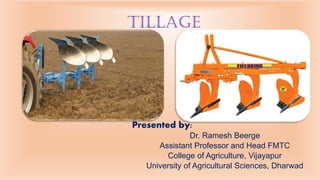
  • 1. Presented by: Dr. Ramesh Beerge Assistant Professor and Head FMTC College of Agriculture, Vijayapur University of Agricultural Sciences, Dharwad Tillage
  • 2. INTRODUCTION ➢ Tillage is one of the oldest practice of agriculture and rapid advance have been made and going on. ➢ It is still far from being an exact science. ➢ One of its major objective is to improve tilth but not defined clearly. ➢ It involves both the biological and physical conditions of soil in relation to plant growth. ➢ There is no adequate method available for evaluating the tilth produce by implement. ➢ It is the mechanical manipulation of soil to provide favorable condition for the crop production. 2
  • 3. • Tillage operations in various forms have been practiced from the very inception of growing plants. • Primitive man used tools to disturb the soils for placing seeds. • The word tillage is derived from the Anglo-Saxon words tilian and teolian, meaning to plough and prepare soil for seed to sow, to cultivate and to raise crops. • Jethrotull, who is considered as Father of tillage suggested that thorough ploughing is necessary so as to make the soil into fine particles. • Tilth is a physical condition of the soil resulting from tillage. • Tilth is a loose friable (mellow), airy, powdery, granular and crumbly condition of the soil with optimum moisture content suitable for working and germination or sprouting of seeds and propagules i.e., tilth is the ideal seed bed. 3 INTRODUCTION
  • 4. TYPES OF TILTH • Fine Tilth refers to the powdery condition of the soil. • Coarse Tilth refers to the rough cloddy condition of the soil. • Fine seedbed is required for small seeded crops like ragi, onion, berseem, tobacco. • Coarse seedbed is needed for bold seeded crops like sorghum, cotton, chickpea, lab-lab etc. 4 • On Season Tillage: It is done during the cropping season (June– July or Sept.–Oct.). • Off Season Tillage: It is done during fallow or non-cropped season (summer). • Special Types of Tillage: It is done at any time with some special objective/purpose
  • 5. Minimum Tillage It is the minimum soil manipulation necessary to meet tillage requirements for crop production Strip Tillage It is a tillage system in which only isolated bands of soil are tilled. Rotary Tillage It is the tillage operations employing rotary action to cut, break and mix the soil. Mulch Tillage It is Preparation of soil in such a way that plant residues or other mulching materials are specially left on a near the surface. Combined Tillage Operations simultaneously utilizing two or more different types of tillage tools or implements to simplify, control or reduce the number of operations over a field are called combined tillage. Tillage is performed by tool, implements or machine. 5 TILLAGE
  • 6.  Tillage operations for seedbed preparation are often classified as primary or secondary, although the distinction is not always clear-cut.  Primary tillage : Initial major soil working operation to reduce strength of soil .  Secondary tillage : Lighter and finer after primary tillage. • Soil Inversion: The process through which the furrow slice is inverted during ploughing. • Soil Pulverization: The process of breaking of soil into smaller aggregates. • Performance Index: The assessment of the overall performance, at a particular set of soil condition. TILLAGE 6
  • 7. • A primary tillage operation constitutes the initial, major soil-working operation after harvest of the previous crop; it is normally designed to reduce soil strength, cover plant materials and rearrange aggregates. • Secondary tillage operations are intended to create refined soil conditions following primary tillage. The final tillage operation prior to planting a crop is usually secondary tillage, but farmers may use more than one secondary tillage operation. • A farmer may prepare a field for planting winter wheat with a single disking operation after harvesting soybeans. • This single disking operation is both the initial tillage operation after harvest and the final tillage operation before planting. Tillage 4
  • 8. Function of Soil Tillage ➢ To develop a desirable soil structure for a seedbed. ➢To control weeds or remove unwanted crop plants. ➢To manage plant residues. ➢To minimize soil erosion. ➢To establish specific surface configurations. ➢To incorporate and mix additives. ➢To accomplish segregation. 5
  • 9. TILLAGE Tools AND EQUIPMENTS • A tillage tool is defined as an individual soil-engaging element, such as a plow bottom or a disk blade. • A tillage implement consists of a single tool or a group of tools, together with the associated frame, wheels, hitch, control and protection devices and power transmission components. • The three hitching configurations available for these implements are integral (mounted), semi-integral (semi-mounted) and drawn (pull- type). • Integral and semi integral implements are attached to the three-point hitch of a tractor, but a drawn implement is attached to the drawbar. • An integral plow, in the transport position, is fully supported by the tractor. 6
  • 10. • The rear furrow wheel of an integral implement provides vertical and lateral support along with the hitch when the implement is in its operating position. • Plowing depth for an integral plow is usually controlled by changing the vertical position of the tractor’s hitch. • A semi-integral plow is supported at the front by the tractor’s hitch and at the rear by the plow’s furrow transport wheel in both the transport and operating positions. • The front of the plow is raised and lowered by the tractor’s hitch while the rear of the plow is raised and lowered by a remote hydraulic cylinder. • A drawn plow is fully supported by its own transport wheels and is raised and lowered by a remote hydraulic cylinder. 7
  • 11. Mechanics of Tillage • Properties affects the reactions of soils to applied force 11 Cohesion Adhesion Frictional Resistance Resistance to compression Resistance to shear Moisture and Colloidal Content Plastic Sticky Plastic Friable (Crumbly) Hard Non Plastic (<15-20 % Clay)
  • 12. Tillage Equipment's ➢Subsoiler ➢Chisel Plow ➢Moldboard Ploughs ➢Disk Plows ➢Rotary Plough Primary Tillage Secondary Tillage ➢Harrows ➢Cultivators ➢Rotary Tillers 8
  • 13. • Used to break through and shatter compacted or otherwise impermeable soil layers and to improve rainfall penetration. • They have heavy standards that can be operated at depths of 45 to 75 cm or more. • Sub soilers do very little soil mixing and no soil inversion. • They are most effective under dry and firm soil conditions. • A sub soiling operation is usually followed by another primary tillage operation before secondary tillage is begun. Subsoiler 9
  • 14. Sub soiler ➢Most sub soilers use the integral hitching configuration, but a few are available with the drawn hitching configuration. ➢Sub soilers frequently rely on the heavy design of the frame and standards for protection during impact with buried rocks. ➢A pull type V-frame sub soiler. 10
  • 16. Chisel Plow ➢ Designed for primary tillage ➢ Operates at depths from 15 to 46 cm. ➢ Aerate the soil with little soil inversion. ➢ Leave a rough soil surface. ➢ Improving water penetration. ➢ Plant residue on the soil surface improves traction. ➢ Function most effectively when the soil is dry and firm because the tools can pass through wet soil with almost no shattering action. 12
  • 17. • It Usually operate a chisel plow at a greater depth than a moldboard plow with the increased draft to break up the plow sole for improved water and root penetration. • Chisel plowing is usually completed in late summer or early fall and is followed by one or more secondary tillage operations during the following spring. • Both the surface roughness and required draft increase with increased operating speed. • Chisel plows are available with integral and drawn hitching configurations. • The shanks are designed with spring-cushion, spring-reset, or spring- trip mountings to protect the tool and frame from impacts with buried rocks. Chisel Plow 13
  • 18. One of the oldest of all agri. Implements and most important & used for primary tillage , Mainly the mould board plough cuts, loose the furrow slice inverts the furrow slice, with more or less pulverization and in doing so it also performs. Moldboard plows 14
  • 19. Moldboard plows Classifications ➢Based on Power Source 1. Animal Drawn 2. Tractor Drawn ➢Based on Hitch System 1. Trailed 2. Semi mounted 3. Mounted ➢Based on Direction of Soil Through 1. Fixed or One Way 2. Reversible a. Mechanical b. Hydraulic 15
  • 20. Plough bottom • Share • Mould board • Land side • Frog Plough accessories • Coulter • jointers • Plough frame and beam • Plough hitch • Cover boards • Weed hooks • Clod buster or plow packer • Moldboard extensions Moldboard plows 16
  • 21. 17
  • 22. 22
  • 23. Moldboard plows • All moldboard plows are equipped with one or more tillage tools called plow bottoms. • Each plow bottom is a three-sided wedge with the landside and the horizontal plane of the share’s cutting edge acting as flat sides and the top of the share and the moldboard together acting as a curved side. • The primary functions of the plow bottom are to cut the furrow slice, shatter the soil, and invert the furrow slice to cover plant residue. • Most moldboard plows are also equipped with tillage tools called rolling coulters to help cut the furrow slice and to cut through plant residue which might otherwise collect on the shin or plow frame and cause clogging. • The vertical edge of the furrow slice left uncut by the rolling coulter is cut by the shin. • The bottoms along with the rolling coulters are responsible for the process function of the moldboard plow. 18
  • 24. Functions : it gives suction, penetration and cuts the furrow slice loose. Some lifting and a slight turning action starts at the share, but little granulation takes place. Types of share:  Slip share – simple in design  Slip nose share – detachable piece  Shin share –extension is provided  Bar share – point of share provided SHARE 21
  • 25. General purpose Have fairly slow turning mould boards which works well in sod and for faster ploughing, stubble ordinary trash and stalk cover High speed It has less curvature at upper end, fitted with throwaway shear when worn out, used for high speed ploughing General purpose High speed Mould board design 22
  • 26. Slatted bottom : Scour better in difficult soil, suitable for sticky soil Stubble bottom : Have an abruptly curved mouldboard which turns the furrow slice quickly, the sharply turned mouldboard thoroughly pulverizes soil. Mould board design 23
  • 27. Semi deep bottom: Have high mould board to permit deep ploughing. Scotch bottom: Used in heavy close textured clay soil and tough sod. The long curved mouldboard sets each furrow slice on edge. Mould board design 24
  • 28. • It is a flat metal piece bolted to the frog, and forms one side of the plough bottom “wedge” . • It helps to absorbs side forces from the turning furrow slice, steadies the plough and helps keep the plough in straight behind the tractor. LAND SIDE 25
  • 29. • Frog is that part of the plough which joins the mould board and share together Frog 26
  • 30. • By cutting the trash into shorter lengths, it enables the plow bottom to cover better. • Cuts through trash which otherwise might drag on the shin and beam. • Helps in cutting the furrow slice free vertically. This assists in securing a clean furrow wall. COULTER 27
  • 31. 28
  • 32. ➢ The jointer has a shape similar to the plow bottom. It cuts out a narrow ribbon of soil just above and a little ahead of the plow. ➢ Any trash it can handle is moved over on the furrow slice toward the ploughed ground in a position to be buried deeper. ➢ A little soil is thrown on top of the trash to lessen its tendency to pitch. ➢ The removal of the ribbon of soil materially aids in presenting trash from appearing in the groves between the turned furrow slices. JOINTER 29
  • 33. • Moldboard plows are the most common implement used for primary tillage, but they are never used for secondary tillage. • They are usually equipped with adjustments to ensure that the plow is level in the longitudinal and lateral directions and that the plow bottom is oriented with the landside parallel to the direction of travel. • Integral moldboard plows have the lowest purchase price and the best maneuverability for small and irregular fields. • However, they are limited in size due to tractor stability and the lift capacity of the hitch. • The furrow transport wheel of a semi integral plow is automatically steered to provide more maneuverability than for a drawn plow. • Both integral and semi-integral plows improve a tractor’s traction by applying a downward force on the hitch. Moldboard plows 30
  • 34. • Drawn plows provide the most uniform plowing depth, but have the highest purchase price. • Moldboard plows are frequently equipped with automatic reset standards that allow a plow bottom to move rearward and upward to pass over an obstacle, such as a rock, without damage. • A hydraulic cylinder or a spring mechanism automatically moves the bottom to its original position after it passes over the obstacle. • Most moldboard plows are designed to turn the furrow slices only to the right. • Two-way plows, however, have two sets of opposed bottoms that can be used selectively. Moldboard plows 31
  • 35. • With this arrangement, all the furrows can be turned toward the same side of the field by using the right-hand bottoms for one direction of travel and the left-hand bottom on the return trip. • The two sets of bottoms are mounted on a common frame that is rotated 180° about a longitudinal axis to change from one set to the other as shown in Figure 8.5. • In most cases, rotation is accomplished with a hydraulic cylinder that is part of the plow. • Two-way plow eliminates the back furrows and dead furrows, leaving the field more nearly level for irrigation or drainage. • Two-way plows are also advantageous for terraced fields or contour plowing and for small fields of irregular shape. Moldboard plows 32
  • 36. Adjustment in MB plough Vertical suction 33
  • 38. Adjustment of track width Track width = size of plough +1/2 of single bottom + 3” 35
  • 40. Lateral adjustment of coulter 37
  • 41. Gathering & Casting • In this method plough works round a strip of ploughed land • Ridge is formed exactly midway between the two side boundaries • This method is used if the field has lower elevation in the centre. 39  Whenever a plough works round a strip of un ploughed land it is said to be casting  The tractor with the plough turns to the left each time  A trench will be left in the centre in the end  This method is used in fields having higher elevation in the centre
  • 42. 40
  • 43. • Based on the horsepower of the tractor the matching plough should be selected • Track width should always be correct • Each and every plough adjustment should be carried out • Correct ploughing method is essential • Choose the depth of ploughing as with the type of soil Preparation for OPeration 41
  • 44. Selection of matching plough Draft (Kg) = Size of plough (cm) X depth of ploughing (cm) X soil resistance (kg/cm2) Dbhp = Draft (Kg) X speed (0km/hr) 270 S.N. Type of Soil Soil resistance (kg/cm2) 1 2 3 4 5 6 Sandy soil Sandy loam Silt loam Clay Heavy loam Gumbo 0.2 0.3 0.35 - 0.5 0.4 - 0.56 0.5 – 0.7 1.0 – 1.4 42
  • 45. Plough Attachment The order of attachment should always be • Left lower link • Right lower link • Top link 43
  • 46. Adjustments Top link setting • If the front bottom goes deeper then the rear , the top link should be lengthen • Shorten the top link if the rear bottom penetrate more then the front bottom Lower link setting • Use leveling lever provided at the right site of the tractor to get plough frame parallel to the ground 44
  • 47. • Each furrow must be perfectly straight from end to end • Soil must be pulverize from top to bottom of the furrow • The outline of the furrows should be a point without break or depression • All beck furrow must be a slightly raised and all trash completely covered • Furrows must be thoroughly uniform with one another • Dead furrow must be as less as possible Ploughing Operation 45
  • 48. Suitability • It is adopted to conditions where MB plough will not work • It is suitable fro dry hard ground that cannot be penetrated with MB plough • • Rough stony & rooted ground where disc will ride over the root • Sticky waxy soil where MB plough does not scoured • Soil where deep reclamation work is required 46
  • 49. • The common disk plow consists of a series of disk blades mounted individually on a frame supported disc blades each with its own bearing. • Disc: It is soil working tool of plough. • The disks used in the disk implements are either conical or spherical (i.e., sections of hollow spheres). • Both blades have a spherical radius associated with the concavity of the blades. • A conical blade has its outside surface flattened to a specific cone angle. • The blade angle of a spherical blade is defined as the tangent at the edge surface area of the blade. Standard DISC PLOW 47
  • 50. • Disk plows are used for primary tillage and are available in integral, semi-integral, and drawn hitching configurations. • They are most suitable for conditions under which moldboard plows do not work satisfactorily, such as in hard, dry soils, and in sticky soils where a moldboard plow will not scour. • Scrapers, furnished as standard equipment on most disk plows, assist in covering plant residue and inverting the soil and prevent soil buildup in sticky soils. • Reversible disk plows have an arrangement whereby the disk angle can be reversed at each end of the field to permit one-way plowing. DISC PLOW 48
  • 51. • Under most conditions, and particularly in hard, dry soils, any disk tool must be forced into the ground by its weight rather than depending upon suction as does a moldboard plow. • Consequently, disk plows are built with heavy frames and wheels (total masses of 180 to 540 kg/disk blade), and even then additional mass must sometimes be added to obtain a desired depth. • The soil penetration ability of a disk plow depends upon disk diameter, tilt angle, and disk angle. • Whereas the moldboard plow absorbs side forces mainly through the landsides, a disk plow must depend upon its wheels for this purpose. • A standard disk plow does not have special attachments to protect its disk blades from damage due to impact with rocks buried in the soil. DISC PLOW 49
  • 52. • Usually, the disk plow is able to withstand impact forces because of its heavy frame and its lower operating speed. • The disk blades are set at an angle, called the disk angle, from the forward line of travel, and also at a tilt angle from the vertical. • Standard disk plows usually have three to six blades, spaced to cut 18 to 30 cm/disk. • The disk angles vary from 42° to 45° and the tilt angles vary from 15° to 25°. The disk diameters are commonly between 60 and 70 cm. DISC PLOW 50
  • 53.  Concave discs  Disc bearing  Disc scraper  Standard  Cross shaft  Frame  Furrow wheel Main parts of disc plough 51
  • 55. TYPES OF DISC PLOUGH • Based on power source: a. Tractor drawn • Based on type of hitch: a. Trailed b. Semi mounted c. Mounted • Based on direction of through of soil a. One way b. Reversible • Based on mounting of disc a. Standard disc plough b. Vertical plough 53
  • 56. S. No. Particulars Standard disc plough Vertical disc plough 1 Mounting of disc On individual axle On common axle 2 No. of Discs 1 to 6 5 to 24 3 Size of Discs 60 to 75 cm 40 to 60 cm 4 Spacing between discs 18 to 30 cm 18 to 22 cm 5 Concavity of discs More Less 6 Depth of cut More (20 to 40 CM) Less (8 to 10 CM) 7 Angle to the direction of travel 42 to 450 35 to 600 8 Tilt angle 15 to 250 00 9 Weight per disc 200 to 600 kg 50 to 100 kg 10 Draft requirement High Low 54
  • 57. Scraper • Each disc is equipped with the scraper which gives good turning effect to furrow slice for better covering of trash much better . • It also help to clean the disc to get better pulverization • There are three types of scraper 1. MB – best trashes 2. Disc – heavy soil 3. Hoe – sticky soil 55
  • 58. Standard: ➢Connect the disc bearing to the plough beam, However in some of the design there is – no standard beam is bend down for disc attachment. Cross shaft: ➢Steel shaft fitted to the plough at front at front at right angle to the beam Both ends have crank opposed to each other. The width of cut can be changed by rotating the CR Shaft. Bearing: ➢ Roller bearing are usually mounted in pairs taper roller bearing absorb forces in all direction and can readily adjusted. Furrow wheel: ➢ It is fixed at rear end of the plough to main plough beam Purpose – to stabilize the rear end of the plough and to hold it in the position to control the width of cut by the front disc. 56
  • 59. ➢Cutting angle adjustment ➢Width of cut adjustment ➢Leveling the plough ➢Tightening the bearing ➢Scraper adjustment ➢Furrow wheel adjustment Adjustments 57
  • 61. Listers • A liste r o r m id d le b re a ke r is b a sica lly th e sa m e a s two o p p o se d M B p lo w b o tto m p la ce d b a ck to b a ck with o u t la n d sid e . • Sid e co m p o n e n ts o f th e u se fu l so il fo rce s b a la n ce e ach o th e r so that resultant useful force lies in a vertical plane in direction of of travel travel . . • Normally no rotational effect would be expected. • Some crops like corn and cotton are planted with listers having planter planter attachments attachments that places seed in the soil. 61
  • 62. Moldboard Type Ditchers • Tools similar to listers but with much larger MB are available for making ditches for the distribution of irrigation water or for drainage. 62
  • 63. SECONDARY TILLAGE Secondary tillage means stirring of the soil at shallower depth. Its objectives are: ➢To improve the seed bed by pulverization of soil. ➢To conserve the moisture & reduce evaporation. ➢To cut, turn & mix crop residues in soil. ➢To destroy weeds. 59
  • 64. Rotavator / Rotary Tiller ➢Preparing the land suitable for sowing (without overturning of the soil ) ➢For eradicating weeds ➢Mixing manure or fertilizer into soil 60
  • 65. Advantages ➢Rapid seed bed preparation ➢Reduce draft compared to the convectional tillage implement ➢Less power loss ➢Soil compaction reduce ➢Tractor weight reduce ➢Negative draft implement which pushes tractor 61
  • 66. COMPONENTS Slip Clutch It protect the tiller transmission against excessive load encountered while working. The clutch designed automatically as soon as safety setting is exceeded. Sometimes instead of this shear bolt is provided. Gear box The gearbox is used to reduce the speed receiving from the tractor toward desired rotor speed according to field condition. Side Drive It consists of chain and sprocket assemble. There are two sprocket where the upper sprocket receives the drive from gearbox and the lower sprocket transfers it to the rotor shaft. Blade It enter into the soil to cut it. There are about 26 to 36 blades bolted to flanges on the rotor shaft. Different type of blade are L-shaped,C-shaped,Long shank blade etc. 62
  • 67. 63
  • 68. Adjustment • Adjust the top link of the tractor to level. • Lift the rotavator a little above the ground and adjust the side to side level such that all the blade have the same clearance. • Change the rotor speed if possible if possible to obtain the desired tilth. • Rise or lower the shield for coarse, medium or fine tilth. • Change the number of blades according to field conditions. • Check the slip clutch form time to time . 64
  • 69. DISC TYPE HARROW ➢ Disk harrows are adopted to wide variety of uses and do an effective job of covering and cutting. ➢Disc harrows are available as trailed type and mounted type. These are further classified as: ➢Single action disc harrow ➢Double action disc harrow 65
  • 70. ➢Disc Blades: The blade of harrow are concave in shape and have a sharp edge. The diameter and thickness varies depending upon the harrow type, size and weight. In general a thickness of 3 mm to 9mm and diameter of 40 cm to 60 cm. The blade spacing varies between 18 to 36 cm depending upon the nature of work. A spool made of cast iron with machined end is used for spacing. ➢Gang: A group of more than two discs which fitted on a shaft with spacers in between them is known as a Gang. The disc mounted on a shaft are tightened with the help of washer & nut. ➢Bearings: The gang on the frame is mounted by bearing housing with bearings, which can be frictional bearing filed with grease or antifriction. Bearings are subjected to axial thrust by angling of shaft, countered by the edge of the spool. ➢Main frame- The frame is the main body on which gangs are attached through bearing standard. For each gang of a disc a heavy duty channel section or square section frame is used. Pulling & hitching arrangement made at the front gang frame. Constructional Features 67
  • 71. Disk tillers • The disk tiller is also known as one-way disk plow, vertical-disk plow, harrow plow, and wheat land plow. • It is similar to a disk plow in regard to the frame, wheels, and depth control, but the disk tiller blades are uniformly spaced along one axle or gang bolt and clamped together through spacer spools so the entire gang rotates as a unit. • This implement is used in dryland grain-growing regions for shallow tillage (often only 8 to 13 cm) and mixing plant residue with the soil. • The soil surface is left rough with visible plant residue to reduce soil erosion. Disk tillers are used for primary tillage and are frequently used in subsequent operations for summer fallowing. • Some disk tillers are equipped with seed and fertilizer attachments to accomplish seedbed preparation, seeding, and fertilizing in a single operation. 68
  • 72. • The blades of a disk tiller are somewhat smaller than those of a standard disk plow, the most common diameters being between 51 and 61 cm. • They are generally spaced 20 to 25 cm apart along the gang bolt. • The width of cut per blade depends upon the spacing and upon the gang angle (adjustable) between the gang axis and the direction of travel. • Gang angles range from 35° to 55°, with 40° to 45° being most common. • There is no tilt angle, and the disk angle is commonly between 35° and 55° (disk plow disk angles are 42° to 45°). • Since disk tillers are primarily for relatively shallow tillage, they are built much lighter than disk plows (usually 45 to 90 kg/blade). • They are available with integral and drawn hitching configurations. • Most disk tillers move the soil only to the right, but reversible models are available which can move the soil in either direction. Disk tillers 69
  • 73. Single action disc harrow ➢It is a harrow with two gangs placed end to end, which throw the soil in opposite directions. 70
  • 74. Double action disc harrow ➢It consists of two or more gangs , in which a set of one or two gangs follow behind the set of the other one or two ,arranged in such a way that the and back gangs throw the soil in opposite direction. Thus the entire field is worked twice in each trip. ➢It may be of two types : • Offset disc harrow Tandem disc harrow 71
  • 75. Double action disc harrow 73
  • 76. PENETRATION OF DISCS ➢Penetration of disc depends and tend to increase upon: • Increasing the disc angle • The weight of the harrow • Lowering the hitch point on the tractor • Reducing the forward speed • The sharpness of the discs, relatively thin disk blades • The size of the discs (Smaller diameter blades) • The concavity of the discs (Less) • The angle of the hitch 74
  • 78. SPIKE TOOTH HARROW ➢Teeth are like spikes, so is the name. ➢Used to smooth and level the soil after plowing. ➢Stir the soil up to 5 cm. ➢frame is triangular or rectangular. ➢ Rigidly attached pointed pegs of about 23cm. long. ➢Depth of penetration is increased by weight. 77
  • 79. SPRING TYPE HARROW ➢Used to loosen the previously ploughed soil. ➢Penetrate more than the spike tooth harrow. ➢To remove stubbles & hidden roots, weeds. ➢The tines can be removed for sharpening. 78
  • 80. BLADE HARROW ➢Popularly known as ‘BAKHAR’. ➢Does not go deep in soil. ➢Used for killing of weeds & covering of trash. ➢Width harrow varies between 38-108 cm. 79
  • 81. CULTIVATORS ➢Cultivators are used after the seeds have germinated. ➢Used for opening the land, preparing the seed bed. ➢Tractor mounted cultivators are also available which may be shovel type and sweep type. ➢The number of the tines is in odd number & most popular tillers are 7, 9, 11 & 13. ➢7, 9, & 11 tine tillers are used for tractors up to 35 HP, 13 tine tiller is used for tractor having above 50 HP. 80
  • 82. TYPE OF CULTIVATORS ➢Rigid Tine Tiller It has a tine made out single piece heat treated steel forging & are designed to avoid trash collection. They carry reversible point made of heat treated hard carbon steel. Rigid tine tillers are sweep type, shovel type, duck foot type, etc. ➢Springed loaded tiller It having two sturdy spring mounted on steel pins. The tines are single piece forgings of heat treated medium carbon steel. The tines are so designed as to avoid trash collection. 81
  • 84. Fundamentals • Force is any action that changes or tends to changes the state of rest or motion of body. • Specified by its magnitude, direction and point of application. • Pull on an implement is the total force exerted upon the implement by power unit. • Draft is the horizontal component of pull parallel to the line of motion. • Drawbar hourse power is the power actually required to pull or move the implement at a uniform speed. 84
  • 85. Power at the Drawbar • The power available at the drawbar, sustainable over a distance of at least 20 metres. • The mean maximum sustained pull, which the tractor can maintain at the drawbar over a given distance, the pull being exerted horizontally and in the vertical plane containing the longitudinal axis of the tractor. • The line of draught shall be horizontal. • The height of the drawbar shall remain fixed in relation to the tractor during each test. • It shall be chosen by the manufacturer in such a way that the direction of the tractor can be controlled when it develops maximum drawbar pull. • In the case of wheeled tractors, the following relationship shall be maintained: PH ≤ 0.8 WZ Where: • P is the maximum drawbar pull; • H is the static height above ground of the line of draught; • W is the static weight exerted by the front wheels on the ground; and • Z is the wheelbase. 85
  • 86. Implement Types 1. Trailing or Towed or Pull Type Implements: They have wheels which support the majority of the implement weight. 2. Semi mounted Three Point Hitch or Mounted Type Implements : Semi mounted implements have wheels which support most of the implement weight, but the implement does not articulated horizontally. Mounted and three point hitch implements are fully supported by the tractor. These implements are raised and lowered vertically by tractor hydraulic lift systems. 3. Stationary Type Implements: Used in a fixed position relative to the tractor and the implement. 86
  • 87. Types of Linkages (a) Single-axis or single-point hitches (b) Two-axis or three-point hitches with vertically converging links, (c) Two-axis hitches with parallel links. 87 Current Types of Three Point Hitches 1. Free Floating 2. Force Sensing in Upper Links (30- 60 kW) 3. Force Sensing in Lower Links 4. Draft Load Sensing in Transmission Torque Load 5. Rear Gage Wheel Actuated with Sensing Hitch 6. Hydraulic Pressure Sensing in Lift System
  • 88. 88 1 Upper link 11 Lift Rods 2 Lower Link 12 Mast 3 Upper Hitch Point 13 Mast Height 4 Lower Hitch Point 14 Lower Hitch Point Height 5 Upper Link Point 15 Levelling Adjustment 6 Lower Link Point 16 Lower Hitch Point Span 7 Upper Hitch Attch. 17 Linch Pin Hole Distance 8 Lower Hitch Attach. 18 Movement Range 9 Upper Link Attach. 19 Transport Height 10 Linch Pin 20 Lower Hitch Clearance
  • 89. Draft of Plows • Hitch as a single articulated point or combination of articulated points and links through which the tractor delivers tractive effort in the form of pull or push to counteract a draft force. • The tractor hitch is required to develop a line of pull to counteract an implement line of pull. • This line of pull is the total resultant force acting on the implement. Parameters Effects on Draft • Effect of soil type and Condition • Effect of Depth of Plowing • Effect of Width of Cut • Effect of Moldboard shape • Effect of attachments • Effect of Rear Furrow Wheel • Effect of Speed upon Draft and Performance 89
  • 90. Advantages of Mounted Implements • Greater maneuverability of the tractor and implement combination • Better transport characteristics of the tractor and implement combination. • Lower cost implement • Ability to use more of the mass of the implement for dynamic loading of the tractor drive wheels • The combination is safer under load 90
  • 91. Design Requirements of the mounted Hitch 1. Provision for Depth Control of Implement 2. Provision for Load Transfer to Drive Wheel of Two Wheel Drive Tractor 3. Provision for Lateral Sway and Centre Ability 4. Provision for Interchangeability of implement and Tractors 5. Provision for fore and after Leveling of the implement 6. Provision for Limiting Sway of the Implement 7. Provision for Lateral Levelling of the Implement 8. Provision for Locking Hitch Laterally in Transport or When Used with PTO and Semi Mounted Implement. 9. Provision for Quick and Easy Attachment of Implement 10. Provision for Adequate Lifting Capacity by the Hydraulic System 11. Provision for Independent Vertical Float of Each Lower Link Hitch Point 12. Provision for Pitching the implement as it is raised. 13. Provision for Simple and Easy Adjustment of the Hitch 91
  • 92. Hitching of Trailed Implement Directions for hitching trailed implements often refer to the center of resistance of a tool as a fixed point and state that the hitch should be adjusted so that the line of pull passes through this center of resistance. • The line of pull must necessarily pass through this center of resistance, regardless of how the implement is hitched; otherwise the system could not be in equilibrium. • As the hitch is changed the soil forces automatically readjust themselves (within the limits for stabilized operation of the tool) to move the center of resistance to the new line of pull, and thus maintain equilibrium. • The function of proper hitching is to establish the center of resistance in the position that is most desirable from the standpoints of the effect of the pulling force upon the tractor and the magnitude and distribution of parasitic forces acting upon the implement. 92
  • 93. 93 ➢ Originally, three-point hitches were made such that the hydraulic power was used only when the implement was raised out of the working position for transport. ➢ During working no hydraulic power was applied. ➢ The forces in the three links would then have to act along the links because the links had more or less frictionless joints at both ends. ➢ In this way a vhp could be established. ➢ As can be seen, this vhp is far ahead of the actual hitch point (ahp) used for pull- type implements. ➢ A fairly small load transfer from the front wheels would occur even if the draft force and the load transfer from the implement were considerable. ➢ If the links of this hitch were adjusted such that they were almost parallel, the vhp would be far ahead of the tractor. ➢ The motion of an implement relative to a tractor will be almost parallel up and down, which is desirable, for instance, for a cultivator. ➢ For a plow, the vhp should be closer to the rear of the tractor in order to make the plow self-adjusting in depth. FREE-LINK THREE-POINT HITCHES
  • 94. 94 • If the operator wants to increase the amount of load transfer or to be able to control the implement according to working conditions, hydraulic power could be used to apply a lift force in the lower links of the three-point hitch. • The maximum load transfer that could take place from the implement to the tractor is W1 = L x5 /x6 • Where W1 is the weight of the implement, L the lift force at the end of the link, x6 the distance of the load behind the hp, and x5 the distance of the end of the link behind the hp. • It would be noticed that if the hp is located far ahead of the tractor the implement load may be located far behind the tractor and the hydraulic system will still be able to lift it. • This will make the tractor unstable and consequently require an improvement of the tractor stability by added front-end ballast. Powered three-point hitch
  • 95. Horizontal Hitching • It is not always possible to have the horizontal center of resistance of an implement directly behind the center of pull of the power unit, particularly for narrow implements and wide-tread tractors. • The alternatives are a central angled pull, an offset straight pull, or an offset angled pull, when referred to the center of pull of the power unit. • These conditions are sometimes all referred to loosely as "side draft," but technically, side draft should be considered only as the side component of an angled pulling force. • The central angled pull does not affect tractor steering, whereas the off set pulls do. 95
  • 96. 96 Draft of Plows under Various Conditions
  • 97. 97 ➢The vertical distance D between the top of the drawbar at the hitch point and the centre line of the power take-off splined shaft shall be between 150 mm and 300 mm; however, 200 mm is recommended. ➢ The vertical distance between the top and the draw-bar at the hitch point and the ground line shall be 380 + 50 mm. ➢ The horizontal distance A between the hitch point of the tractor drawbar and the end of the spilled shaft of the power take-off shall be 355 + 10 mm. ➢ The horizontal distance B between the hitch point on the tractor drawbar and the rear-most point on the standard sized wheels/tracks lug or fender of the tractor shall be not less than 75 mm. ➢ The diameter of the hitch at the end of the tractor drawbar shall be 22 mm. Location on tractor
  • 98. 98 The power take-off shaft shall be provided with a shield incorporating the attaching point for the shield of the driven machine. The shield shall have sufficient strength to support live load of about 100 kg without taking a permanent set. The shielding of the power drive line, including all yokes and joints, shall be adequate to prevent the operator from coming in contact with positive-driven rotating members of the power drive line. This protection shall be adequate during turns and under load. Where integral-type power take-off driven implements are of a design requiring removal of the tractor shield, such implement shall also include adequate protection for that portion of the tractor power shaft which protrudes from the tractor. The power take-off shaft shall be covered by a shield or by other protective means when not connected to a drive assembly. Safety requirements
  • 99. Characteristics of PTO Types PTO TYPE Nominal Diameter, mm Number & Type of Splines PTO (RPM) 1 35 6 Straight 540 2 35 21 Involute 1000 3 45 20 Involute 1000 99 Zone of clearance In order to ensure that the articulation of the implement or trailer is not obstructed, a minimum zone of clearance of 80 mm around the power take-off shall be maintained. No part of the tractor or any accessory shall encroach on this zone.
  • 100.
  • 101.
  • 102. 102
  • 103. 103
  • 104. 104
  • 105. Four joint with Telescopic 105