1. UCCN1003 Data Communications and Networks
Lab 02: Build LAN with Cisco Router
Instructions:
1. Read the “Introduction” section for the background.
2. Perform all the lab exercises, starting with exercise 1.
3. Follow all the steps.
4. Record the results in all italic bold actions (by screen capture or copying).
5. Paste your screen captures on a Word Document and save it.
6. Answer all the questions in italic.
7. Write your answer in the same Word Document.
8. Please follow the sequence of the exercises, and don‟t skip any step.
9. Please keep your word document. You will need it for your tests and exam.
Introduction
In this lab, you will learn the process of connecting and configuring PCs, servers, and routers in
an Ethernet LAN using Packet Tracer. You will learn and experience the basic configuration
procedures for Cisco network devices. These procedures require the use of Cisco Internetwork
Operating System (IOS) and the related commands. An understanding of the configuration
process using the IOS is essential for network administrator and network engineers.
Exercise 1: Setting up the Router with a console PC
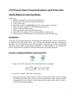
1. Drag a Cisco 1841 router and a PC into the Packet Tracer workspace.
2. Select the “Console” cable from “Connections”.
3. During the connection, select “RS 232” when you click on PC0. Select “Console” (means
the console port of the router) when you click on the Router0. (Note: In the real world,
configuration of Cisco Router is done using this blue cable called rollover cable, as
shown in the following diagram).
1
2. Exercise 2: Adding Extra Module to the Router
1. Click here
2. Click here 3. Click here to off
the router’s power
(green = power on)
1. Double click on Router0. First, click on “Physical” tab. Then click on the “WIC-
1ENET”. Click on the switch to “off” it. (Note: “WIC-1ENET” provides an extra
Ethernet port for the router, which has a bandwidth of 10Mbps. Fast Ethernet has a
bandwidth of 100Mbps)
5. Click here to on
4. Click here and the switch again
drag the module
into the slot
2
3. 2. Click on the module located at the bottom right corner and drag it into the left slot. Then
click on the switch to “on” router again.
Exercise 3: Configuring the Router using Terminal
1. Double click on PC0, click on “Desktop” tab, and then click on “Terminal”. (Note: In
real life you can use HyperTerminal or PuTTY for Windows XP.)
2. Set the parameters according to the above screen, click “ok” to continue.
3. From now on, use the “Terminal” of PC0 to configure the router instead of using the CLI
in router. (Note: “Terminal” is how a router is configured in the real world. “CLI” is just
a “convenience” in Packet Tracer. “CLI” does not exist in the real world”.)
The “CLI” of Router does not exist in the real world.
3
4. This is how router is configured in the real world, with a rollover
cable and a Terminal program.
4. Wait for the booting up of the router. Type “no” (as shown in the above screen).
5. Hit enter key to get the first router prompt.
Router>
Exercise 4: Some Basic Commands and Password Setup for Router0
1. Type “enable” to get into privileged mode. The pound sign (#) indicates you are now in
privileged mode. Type “disable” to return to user mode or exit from privileged mode.
Type “en” again to get into privileged mode again.
Router>enable
Router#disable
Router>en
Router#
2. Type “?” to list all commands available in the current command mode (or prompt). If the
list is too long, hit space bar to continue.
Router#?
4
5. 3. Type “c?” to list all the possible commands that start with the letter „c‟.
Router#c?
4. Type “cl?” to list all the possible commands that start with the letters „cl‟.
Router#cl?
clear clock
5. Type “clock”. After you hit enter the “% Incomplete command” tells you that more
parameters need to be entered.
Router#clock
% Incomplete command.
6. Type “clock ?”. This will show all subcommands for this command (in this case, Set,
which sets the time and date).
Router#clock ?
set Set the time and date
7. Type “show clock” to check the time and date.
Router#show clock
8. Type “clock set 12:14:01 25 Dec 2010” to check the time and date.
Router#clock set 12:14:01 25 Dec 2010
9. Type “show clock” again to check for the new time and date.
Router#show clock
10. Type “show version” to display the information about the current Cisco IOS software.
Router#show version
11. Type “show flash” to display the information about the flash memory.
Router#show flash
12. Type “show history” to list all commands in the history buffer.
Router#show history
13. Type “show ip interface brief” to display a summary of all interfaces.
Router1#show ip interface brief
5
6. 14. Type “show interface” to display detailed information on each interface. (Hit space bar to
continue when you see –more--)
Router1#show interfaces
15. Type “configure terminal” or “conf t” to move to global configuration mode. This prompt
indicates that you can start making changes and configuration in the router.
Router#conf t
Router(config)#
16. Type “hostname uccn1003” to change the “prompt” name.
Router(config)#hostname uccn1003
uccn1003(config)#
Exercise 5: Password Setup for Router0
1. Configure a secret password of “good” for enable command.
uccn1003#conf t
uccn1003(config)#enable secret good
2. Configure a password of “nice” for console mode. (Note: Whenever a user tries to enter
into the console command line, a password is required.)
uccn1003(config)#line console 0
uccn1003(config-line)#password nice
uccn1003(config-line)#login
3. Exit to the very beginning of the router CLI.
uccn1003(config-line)#end
uccn1003#disable
uccn1003>exit
Press RETURN to get started.
4. Try the passwords: When you hit enter (into console command line) and being asked for
a password, type “nice”. When you type “enable” and being asked for a password, type
“good”.
User Access Verification
Password:
uccn1003>enable
Password:
uccn1003#
6
7. 5. Configure a banner that says “Welcome to UCCN1003 - Authorized Users Only”.
uccn1003#conf t
uccn1003(config)#banner motd #
Enter the text followed by the '#' to finish
Welcome to UCCN1003 - Authorized Users Only#
uccn1003(config)#exit
6. Test the banner and console password by logging out of the router and logging back in.
Get into enable mode after successfully logging into the console.
uccn1003#logout
<Enter>
(Try to notice this part…)
User Access Verification
password:nice
Router1#en
password:good
Exercise 6: Setting up LANs
1. Add extra switch, PCs and server in order to form the above network. Configure the IP
address of the fa0/0 and fa0/1 port according to the following commands. MAKE SURE
that fa0/0 of Router0 is connected to switch0 fa0/1, and fa0/1 is connected to the server.
Use “Connection → Copper straight-through” to perform the connection between
Router0 and Switch0. Use “Connection → Copper cross-over” to perform the
connection between Router0 and Server0. <tab> in the command stands for tab key.
uccn1003#conf<tab>
uccn1003#configure t<tab>
uccn1003#configure terminal
7
8. uccn1003(config)#int fa0/1
uccn1003(config-if)#ip address 192.168.10.254 255.255.255.0
uccn1003(config-if)#description connection to DNS server
uccn1003(config-if)#no shutdown
uccn1003(config-if)#int fa0/0
uccn1003(config-if)#ip address 192.168.15.254 255.255.255.0
uccn1003(config-if)#description connection to LAN 1
uccn1003(config-if)#no shutdown
2. You may exit configuration mode by keying ctrl-z. This will bring you back to the
privileged mode prompt. You could also accomplish the same thing by keying “exit”
twice. The exit command moves you back one level. Or keying “end” to achieve what
can be done with <ctrl-z> (Press “crtl” key and “z” key, don‟t type it).
uccn1003(config-if)#<ctrl-z>
uccn1003#
OR
uccn1003(config-if)#exit
uccn1003(config)#exit
uccn1003#
OR
uccn1003(config-if)#end
uccn1003#
3. Display the active configuration in DRAM by typing:
uccn1003#show running-config
4. Display the saved configuration in NVRAM. Is there “anything” after you have typed the
command?
uccn1003#show startup-config
5. Save the running (active) configuration to NVRAM by typing:
uccn1003#copy running-config startup-config
Destination filename [startup-config]? {Press Enter}
6. Now display the contents of NVRAM again. This time, you should see the active
configuration saved in NVRAM.
7. Issue the command to show which Layer 3 protocols are currently running on the router.
uccn1003#show protocols
8. Lastly, configure server IP according to the following.
8
9. Exercise 7: Setting DHCP services in Router
1. Use the following commands to set up the DHCP for the LAN, in Router0. It is Router0
that will act as a DHCP server. (Note: Besides a DHCP server, Cisco router can also
provide DHCP service.)
uccn1003#conf t
uccn1003(config)#ip dhcp pool internal
uccn1003(dhcp-config)#network 192.168.15.0 255.255.255.0
uccn1003(dhcp-config)#default-router 192.168.15.254
uccn1003(dhcp-config)#dns-server 192.168.10.1
uccn1003(dhcp-config)#end
uccn1003#
2. Type “ipconfig /renew” to obtain the dynamic IP addresses from Router0 for PC1, PC2
and PC3.
3. Now go to Router0, and key in the following command.
uccn1003#show ip dhcp binding
Exercise 8: Telnet to Router for CLI
1. Configure a password of “baik” on Router0 that will enable remote users (the PCs) to
Telnet into it:
uccn1003#conf t
uccn1003(config)#line vty 0 4
uccn1003(config-line)#password baik
uccn1003(config-line)#login
uccn1003(config-line)#end
uccn1003#
2. Go to PC1, open the command prompt and type “telnet 192.168.15.254”. Hope that you
still remember which password (there are 3 passwords now: the console password, the
enable password, and the telnet password).
9
10. 3. Instead of using the “terminal CLI”, we can now continue to use the “telnet CLI” to
perform the configuration of the router.
uccn1003(config)#ip host dns_server 192.168.10.1
uccn1003(config)#end
4. Verify that the name “dns_server” is in Router0‟s host table with the show hosts
command.
uccn1003#show hosts
5. Ping „dns_server‟ and verify that the pings succeed.
uccn1003#ping dns_server
6. Go to PC2 and telnet to Router0. Do the same to PC3, telnet to Router0 too.
7. Go to any telnet sessions and type
uccn1003#show users
Exercise 8: TFTP Server (TFTP = trivial file transfer)
1. Copy your running-config to the tftp-server. You will be prompted for the address of the
tftp-server (192.168.10.1). Make sure that the TFTP service is on in the 192.168.10.1.
You will also be prompted for a file name (uccn1003-confg). Just hit enter.
uccn1003#copy run tftp
Address or name of remote host []?192.168.10.1
Destination filename [uccn1003-confg]? {Press Enter}
2. Go to Server0, “config” tab, and click on “TFTP”. You should find the file “uccn1003-
confg” there.
3. You may restore the configuration you saved on the TFTP server to NVRAM on
Router0.
uccn1003#copy tftp run
Address or name of remote host []? 192.168.10.1
Source filename []? uccn1003-confg
Destination filename [running-config]? {Press Enter}
10
11. Exercise 9: Design a Second LAN with Server
1. Setup the above network with the skills that you have learnt. Add in the extra LAN with
the following specifications:
a) Server1 IP = 192.168.17.1, subnet mask = 255.255.255.0, Gateway IP =
192.168.17.254
b) DHCP range = 192.168.17.5 to 192.168.17.15 (in Server1)
c) Set the DNS server at 192.168.10.1 to have www.hello.com = 192.168.17.1
d) Make a web server with a web page as shown in the following diagram, in Server1
e) Make sure all PCs and servers can ping each other.
f) Make sure all PCs can access the web at www.hello.com
g) Set up a file server in Server0 with a username = “uccn1003” and password “ipass”.
Also set this user name with the privilege of „Write‟, „Read‟, „Delete‟, „Rename‟,
„List‟
h) Use the text editor in PC1. Save a file called “hello.txt” with a text “Hello world!”.
Upload the “hello.txt” file to the ftp server. (Note: ftp command = put filename)
2. If you can‟t finish this exercise in the lab, please download the Packet Tracer and
continue this exercise at home.
11