Higher order elements
•Download as PPTX, PDF•
1 like•3,639 views

In FEA, trial function having order of the polynomial more than two.

Recommended
More Related Content
What's hot
What's hot (20)
Similar to Higher order elements
Similar to Higher order elements (20)
Recently uploaded
Recently uploaded (20)
Higher order elements
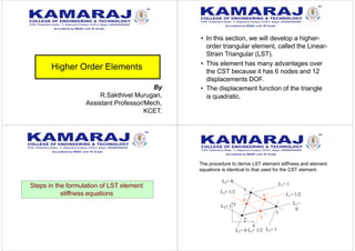
- 1. Higher Order Elements • In this section, we will develop a higher- order triangular element, called the Linear- Strain Triangular (LST). • This element has many advantages over the CST because it has 6 nodes and 12 displacements DOF. • The displacement function of the triangle is quadratic. Steps in the formulation of LST element stiffness equations The procedure to derive LST element stiffness and element equations is identical to that used for the CST element. x 2 3 1 2L = 1 y L3= 1 L1= 1 L1= 1/2 L1= 0 L2= 0 L2= 1/2 L3= 0 L3= 1/2 4 5 6 By R.Sakthivel Murugan, Assistant Professor/Mech, KCET.
- 2. Step 1 : Discretize and Select element types Consider the triangular element shown below: Each node is defined by nodes numbers. Each node has 2 DOFs (displacements in x-,y- directions) x y u1 v1 1 u4 v2 2 u2 6 5 v6 v3 3 u3 v4 4 u6 u5 v5 Step 2 : Select Displacement Functions The variation of the displacements over the element may be expressed as The displacement compatibility among the adjoining elements is satisfied because the 3 nodes defining adjacent sides define a unique parabola. 1 y5 xy4 x3 y2 x2 y3 x4 yx5 y4 x2 y2 x3 yx4 x3 y2 y3 xy3 x 2 xy x2 y xy2 yx PASCAL TRIANGLE The CST and LST are variations of the Pascal Triangle.
- 3. Step 3 : Define the Strain-Displacement and Stress-Strain Relationships Elemental Strains: The strains over a 2D element are: Observe that the strains are linear!! over the triangular element and that is why it’s called a linear-strain triangle (LST). Write The above equation may be written in matrix form as:
- 4. Step 4: Derive the Element Stiffness Matrix and Equations using the Total Potential Energy Approach Step 5,6, and 7: Assembling the global stiffness matrix, determining the global displacements and calculating the stresses, are identical to the procedures used for CST elements. 1 (0,0) 6 (0.5b,0) 2 (b,0) 4 (0.5b,0.5h) 3 (0,h) 5 (0,0.5h) The triangle has a base dimension of b and a height h, with mid-side nodes. We can calculate the coefficients a1 through a6 by evaluating the displacement u at each node.
- 5. Solving for the a’s gives The u displacement equation is
- 6. Comparison of Elements Observations • For a given number of nodes, a better representation of true stress and displacement is obtained using LST elements than is obtained using the same no. of nodes a finer subdivision of CST elements. • The larger the no. of degrees of freedom for a given type of triangular element, the closer the solution converges to the exact one. • Although the CST is poor in modeling bending, we observe from Table 2 that the element can be used to model a beam in bending if sufficient no. of elements is used through the depth of the beam. • In general, both LST and CST analyses yield sufficient results for most plane stress/strain problems provided a sufficient number of elements are used (LST model might be preferred over the CST for plane stress when a relatively small no. of nodes is used). • Most commercial programs incorporate the use of CST and/or LST elements for plane stress/strain problems although these elements are used primarily as transition elements (usually during mesh generation).
- 7. some other elements 4-noded rectangle y a a 1 4 2 b b 3 In local coordinate system 4 ab 4 3 2 1 4 ab ( a x )( b y ) N N 4 ab ( a x )( b y ) 4 ab ( a x )( b y ) x N ( a x )( b y ) N 1 x5 x4 y x3 y2 x2 y3 xy4 y5 x4 x3 x 2 y xy 2 y3 x3 y x 2 y 2 xy3 y 4 xyx2 y2 x y 4 node;p=2 Corner nodes 3 4 1 2 2 2 4ab 2 24ab 2 2 4ab 2 24ab N (a x)(b y) N6 N7 N (a x)(b y) N8 N7 N (a x)(b y) N5 N8 N (a x)(b y) N5 N6 x y a a 1 4 2 b b 3 5 6 7 8 Midside nodes 2 2 8 2 2 2 2 6 2 2 b2 2a (a x) b y N 2b 7 a2 a x (b y) N b2 2a N (a x) b y 2b 5 a2 a x (b y) N 8-noded rectangle 4 node; p=2 8 node; p=3 5 4 3 2 2 3 4 5 x x y x y x y xy y x 3 x 2 y xy 2 y 3 x 4 x 3 y x 2 y 2 xy 3 y 4 xyx 2 y 2 1 x y STATIC CONDENSATION