RJG_Grad_Poster_3 (1)
- 1. Human in the Loop Control for DARPA
Robotics Challenge Hose Task
Ryan Giovacchini
Advisor: Michael Gennert
Robotics Challenge
The DARPA Robotics Challenge (DRC) and Boston Dynamics (BDI) Atlas
robot were designed to expand the use of autonomous/human-in-the-loop
systems in hazardous, degraded conditions common in disaster zones. As
part of the challenge robots were given supervisory control by their human
operators. A crucial part of this was supplying operators with important
information regarding the robots state and environment, and providing an
easy to use and intuitive approach to supplying the robot with the operators
intentions. This work describes the approach to user control currently being
used by WPI-CMU DRC team. More specifically, this work focuses on one
of the five manipulation tasks, the hose task, that required both fine manip-
ulation to line up the hose with the hydrant, as well as larger arm motions
with less accurate positions to reach the hose. Also this task demonstrated
the need to position Atlas relative to the object to be manipulated.
Hose Task
The Hose Task consists of locating and grasping the nozzle of a fire hose,
unreeling the hose and attaching the hose nozzle to the wye connector. The
hose and wye are set up in a warehouse scenario. The hose reel and wye are
mounted to a wall at a height approximately one meter above the ground.
The robot starts about 0.76 meters from the reel and the wye is another 2.5
meters from the hose.
Figure 1: (a)Hose nozzle (b)wye connector
Software
For the DRC Trials each task developed their own graphical user interfaces
(GUIs). For the hose task two unique GUIs were used, one for manipulation
(Fig. 2 (a)) and the other for walking (Fig. 2 (b)).
Figure 2: (a) Manipulation GUI (b) Walking GUI
User Interfaces
Manipulation GUI Fig. 2 (a)
• Used MoveIt! a software for serial manipulators
– Allows the user to click and drag the end-effector to a desired location
– Generates a path and preview of the robot’s motion
• Additional panel with predefined arm configurations
– Allows the user to quickly get to a desired configuration
Walking GUI Fig. 2 (b)
Figure 3: iRobot Hand
interactive marker
• Used an interactive marker (Fig 3)
– Allows user to position the marker directly
inside of the point cloud
– Simplified process of positioning the de-
sired foot placement
• Additional panel for selecting foot distance
from marker
Custom Hardware
In order to aid in attaching the hose nozzle to the wye, the robot’s hand
was equipped with a finger extension (Fig 4). The finger extension would
come into contact with the rotary collar, and while the hand rotated the hose
nozzle the finger extender ensured that the collar would also rotate. Then
by lifting the finger extension the hand could rotate back without the collar
rotating with it. This process could be repeated until the hose nozzle was
attached.
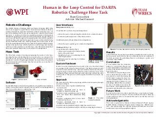
Approach
The course layout for the hose task along with the robot’s trajectory through
it is shown in (Fig 5)
Figure 4: The robot
hand with extension
1. Robot scans course. Operator identified hose
reel and nozzle
2. Operator commands robot to move to
roughly 0.8 meters from hose reel
3. Operator selects predefined script to grasp
hose, and makes final adjustments using
MoveIt!
4. Operator commands robot to move back-
wards and face the wye
5. Operator commands robot to move to
roughly 0.5 meters from wye
6. Operator selects predefined script to align hose nozzle to wye
7. Operator selects predefined script to attach hose using finger extension
Figure 5: The hose task scenario and the robot stepping trajectory
Results
At the DRC Trail, the operator successfully controlled the robot to pick up
the hose nozzle and touch it to the wye within the first twelve minutes of
the thirty provided. By performing these two actioning two points were
awarded to team WRECS.
Conclusion
Figure 6: Atlas at DRC Trials
It was learned that the interactive
marker is a useful and efficient tool
to send commands for orientation and
position of the desired final foot place-
ment of the robot.
The method of using the finger exten-
sion to attach the hose nozzle to the
wye proved to work when using the
robot’s hand to grasp the hose noz-
zle and manually attach it. However,
aligning the nozzle with the wye was
increasingly difficult.This was primar-
ily due to the limited view from the
head camera, when aligning the hose,
the hand would block the view of the wye.
Future Work
In order for the robot to be able to attach the hose, a new method of align-
ment will need to be developed. This new method will need to make use
of other sensors in order to circumvent the need to see the hose and wye
during alignment.
Acknowledgements
This work is sponsored by Defense Advanced Research Project Agency,
DARPA Robotics Challenge Program under Contract No. HR0011-14-C-
0011. Also acknowledge our corporate sponsors NVIDIA and Axis Com-
munications for providing equipment support.
Copyright © 2014 Ryan Giovacchini and the Robotics Program, Worcester Polytechnic Institute