SlideShare a Scribd company logo
1 of 12
Download to read offline
OPERATING INSTRUCTIONS
PA AMPLIFIER A-1706
A-1712
A-1724
Please follow the instructions in this manual to obtain the optimum results from this unit.
We also recommend that you keep this manual handy for future reference.
2
TABLE OF CONTENTS
1. SAFETY PRECAUTIONS ............................................................................... 3
2. GENERAL DESCRIPTION ............................................................................. 4
3. FEATURES .......................................................................................................... 4
4. NOMENCLATURE AND FUNCTIONS
Front ......................................................................................................................... 5
Rear .......................................................................................................................... 5
5. CONNECTIONS
5.1. Speaker Connections ........................................................................................ 7
5.2. Remote Volume Control Connection ................................................................. 7
5.3. Remote Power ON/OFF Control Connection .................................................... 7
5.4. External Equipment Connection
to the LINE OUT and PWR AMP IN Terminals ................................................. 8
6. FUNCTION SWITCH SETTINGS ................................................................. 8
7. SPEAKER ZONE SELECTION ..................................................................... 8
8. INSTALLATION .................................................................................................. 8
9. RACK MOUNTING ............................................................................................ 9
10. CONTROL SETTINGS ..................................................................................... 9
11. BLOCK DIAGRAM ........................................................................................... 10
12. SPECIFICATIONS ............................................................................................ 11
Accessories ............................................................................................................. 11
Optional products .................................................................................................... 11
13. DIMENSIONAL DIAGRAM ............................................................................ 12
3
1. SAFETY PRECAUTIONS
• Be sure to read the instructions in this section carefully before use.
• Make sure to observe the instructions in this manual as the conventions of safety symbols and messages
regarded as very important precautions are included.
• We also recommend you keep this instruction manual handy for future reference.
Safety Symbol and Message Conventions
Safety symbols and messages described below are used in this manual to prevent bodily injury and property
damage which could result from mishandling. Before operating your product, read this manual first and
understand the safety symbols and messages so you are thoroughly aware of the potential safety hazards.
WARNING
Indicates a potentially hazardous situation which, if mishandled, could
result in death or serious personal injury.
Indicates a potentially hazardous situation which, if mishandled, could
result in moderate or minor personal injury, and/or property damage.
WARNING
CAUTION
When Installing the Unit
• Do not expose the unit to rain or an environment
where it may be splashed by water or other liquids,
as doing so may result in fire or electric shock.
• Use the unit only with the voltage specified on the
unit. Using a voltage higher than that which is
specified may result in fire or electric shock.
• Do not cut, kink, otherwise damage nor modify the
power supply cord. In addition, avoid using the
power cord in close proximity to heaters, and never
place heavy objects -- including the unit itself -- on
the power cord, as doing so may result in fire or
electric shock.
• Be sure to replace the unit's terminal cover after
connection completion. Because high voltage is
applied to the speaker terminals, never touch these
terminals to avoid electric shock.
• Be sure to ground to the safety ground (earth)
terminal to avoid electric shock. Never ground to a
gas pipe as a catastrophic disaster may result.
• Avoid installing or mounting the unit in unstable
locations, such as on a rickety table or a slanted
surface. Doing so may result in the unit falling
down, causing personal injury and/or property
damage.
• The socket-outlet shall be installed near the
equipment and the plug (disconnecting device)
shall be easily accessible.
When the Unit is in Use
• Should the following irregularity be found during
use, immediately switch off the power, disconnect
the power supply plug from the AC outlet and
contact your nearest TOA dealer. Make no further
attempt to operate the unit in this condition as this
may cause fire or electric shock.
· If you detect smoke or a strange smell coming
from the unit.
· If water or any metallic object gets into the unit
· If the unit falls, or the unit case breaks
· If the power supply cord is damaged (exposure of
the core, disconnection, etc.)
· If it is malfunctioning (no tone sounds.)
• To prevent a fire or electric shock, never open nor
remove the unit case as there are high voltage
components inside the unit. Refer all servicing to
your nearest TOA dealer.
• Do not place cups, bowls, or other containers of
liquid or metallic objects on top of the unit. If they
accidentally spill into the unit, this may cause a fire
or electric shock.
• Do not insert nor drop metallic objects or
flammable materials in the ventilation slots of the
unit's cover, as this may result in fire or electric
shock.
4
When Installing the Unit
• Never plug in nor remove the power supply plug
with wet hands, as doing so may cause electric
shock.
• When unplugging the power supply cord, be sure
to grasp the power supply plug; never pull on the
cord itself. Operating the unit with a damaged
power supply cord may cause a fire or electric
shock.
• When moving the unit, be sure to remove its power
supply cord from the wall outlet. Moving the unit
with the power cord connected to the outlet may
cause damage to the power cord, resulting in fire or
electric shock. When removing the power cord, be
sure to hold its plug to pull.
• Do not block the ventilation slots in the unit's cover.
Doing so may cause heat to build up inside the unit
and result in fire.
• Avoid installing the unit in humid or dusty locations,
in locations exposed to the direct sunlight, near the
heaters, or in locations generating sooty smoke or
steam as doing otherwise may result in fire or
electric shock.
When the Unit is in Use
• Do not place heavy objects on the unit as this may
cause it to fall or break which may result in
personal injury and/or property damage. In
addition, the object itself may fall off and cause
injury and/or damage.
• Make sure that the volume control is set to
minimum position before power is switched on.
Loud noise produced at high volume when power is
switched on can impair hearing.
• Do not operate the unit for an extended period of
time with the sound distorting. This is an indication
of a malfunction, which in turn can cause heat to
generate and result in a fire.
• Contact your TOA dealer as to the cleaning. If dust
is allowed to accumulate in the unit over a long
period of time, a fire or damage to the unit may
result.
• If dust accumulates on the power supply plug or in
the wall AC outlet, a fire may result. Clean it
periodically. In addition, insert the plug in the wall
outlet securely.
• Switch off the power, and unplug the power supply
plug from the AC outlet for safety purposes when
cleaning or leaving the unit unused for 10 days or
more. Doing otherwise may cause a fire or electric
shock.
CAUTION
2. GENERAL DESCRIPTION
Equipped with 6 Microphone inputs and 5 AUX inputs (simultaneous use of 9 inputs possible), TOA's A-1706,
A-1712, and A-1724 PA Amplifiers are designed to suit PA system applications such as announcements,
BGM and broadcasting in mosques, churches, large rooms and factories.
3. FEATURES
• Power output of 60 W (A-1706), 120 W (A-1712), and 240 W (A-1724).
• All microphone inputs are provided with phantom powering (ON/OFF selectable) and electronically-balanced
combined XLR/phone jack connectors.
• Convenient 2 zone-selector switches for broadcasting.
• An equalizer or other signal processor connectable between PWR AMP IN and LINE OUT terminals to make
fine sound adjustment.
• Tone controls (bass and treble).
• Output level meter.
• Master volume control for overall input signal level adjustment.
An all-pole mains switch with a contact separation of at least 3 mm in each pole shall be incorporated in
the electrical installation of the building.
5
This figure represents the A-1724.
1
3
2
4
56 7
8 9
10
11
4. NOMENCLATURE AND FUNCTIONS
[Front]
1. Power switch
Press to turn ON the power.
Press again to turn the power OFF.
Note: The unit is not completely disconnected
from the power supply even if this Power
switch is turned off.
2. Power indicator
Lights green when the power is switched on.
3. Microphone volume controls [MIC 1 – 4]
Adjust the microphone level.
4. Microphone/AUX volume controls
[MIC 5/AUX 1, MIC 6/AUX 2]
Adjust the microphone or AUX level.
5. AUX volume controls [AUX 3 – 5]
Adjust the AUX level.
6. Bass control
Adjusts bass response. Rotate clockwise to
increase bass output, and counterclockwise to
reduce it. The center position provides flat
characteristics.
7. Treble control
Adjusts treble response. Rotate clockwise to
increase treble output, and counterclockwise to
reduce it. The center position provides flat
characteristics.
8. Zone indicators
Light to indicate the broadcast zone (zone1, 2)
selected with the Zone selector switches.
This figure represents the A-1724.
21
22 2312
13 14
15 16
18 1917 20
[Rear]
6
9. Zone selector switches
Select the desired broadcast zone.
Pressing the ZONE 1 and 2 switches allows the
ZONE 1 and 2 output terminals (14) to output
signals, respectively.
10. Master volume control
Adjusts the overall signal level.
11. LED level meter
Indicates an output level.
12. AC inlet
Connects to the supplied power cord.
13. Ground terminal
A functional ground terminal.
14. Output terminal block
Connects to speakers. Outputs signals at the
ZONE 1 and 2 output terminals when the front-
mounted ZONE 1 and 2 switches (9) are
pressed, respectively. The DIRECT output
terminal continuously outputs signals irrespective
of these switch settings.
15. Recording output terminals [REC OUT]
0 dB, 600 Ω, unbalanced. Output all input signals
before the master volume control. Connect a
cassette deck, etc. when recording the broadcast
contents.
16. Line output terminal [LINE OUT]
0 dB, 600 Ω, unbalanced. Outputs all input
signals. Connects to a signal processor such as
a limiter or equalizer. (Refer to p. 8.)
17. Power amplifier input terminal [PWR AMP IN]
0 dB, 600 Ω, unbalanced. Accepts output signals
from the signal processor connected to the Line
output terminal (16). (Refer to p. 8.)
Inserting an RCA plug disconnects the internal
power amplifier section from the preamplifier
section.
18. AUX input terminal [AUX 5]
–20 dB, 10 kΩ, unbalanced. A combined XLR
(female)/phone jack connector. Accepts external
equipment output signals.
19. AUX input terminals [AUX 3, 4]
–20 dB, 10 kΩ, unbalanced. Monaural RCA pin
jacks. Accept external equipment output signals.
20. Microphone/AUX input terminals
[MIC 5/AUX 1, MIC 6/AUX 2]
–60 dB, 600 Ω, electronically balanced (MIC 5
and 6) or –20 dB, 600 Ω, electronically balanced
(AUX 1 and 2). Combined XLR (female)/phone
jack connectors. The input level can be switched
between MIC and AUX using the function switch
(23).
21. Microphone input terminals [MIC 1 – 4]
–60 dB, 600 Ω, electronically balanced.
Combined XLR (female)/phone jack connectors.
Note
Use an XLR connector when connecting a
phantom-powered microphone to this terminal.
Using a phone plug instead may cause a noise if
it is touched or rotated.
22. Remote control terminal block
(1) Remote power ON/OFF control input
[POWER REMOTE]
Allows remote control of the unit's power
ON/OFF.
No-voltage make contact input.
(2) Remote volume control [REMOTE VOLUME]
Connecting a 10 kΩ linear taper volume control
across these terminals will allow remote control
of Line output and speaker output levels.
23. Function switch
An 8-bit DIP switch. Selects the following
functions:
(1) Phantom power ON/OFF for each MIC 1–6
(2) Input sensitivity for MIC 5/AUX 1 and MIC 6/AUX 2
Refer to p. 8 "FUNCTION SWITCH SETTINGS"
for details.
Usable connectors and plugs
• XLR type male connector • Phone plug
Pin 1: Ground
Sleeve: Ground
Pin 2: Hot
Tip: HotPin 3: Cold Ring: Cold
Be sure to attach the supplied terminal cover after connection completion. Because high voltage is
applied to the speaker terminals, never touch these terminals to avoid electric shock.
7
5. CONNECTIONS
5.1. Speaker Connections
C C 4 16Ω
DIRECT
100 V
ZONE 2
100 V
ZONE 1
100 V C C 4 16Ω
DIRECT
100 V
ZONE 2
100 V
ZONE 1
100 V
Total impedance
167 Ω (A-1706)
83 Ω (A-1712)
42 Ω (A-1724)
4 – 16 Ω 100 V line
100 V line
100 V line
Notes
• Both the 4 – 16 Ω and 100 V terminals cannot be used
at the same time.
• Impedances indicated in the figures represent the total
speaker system (load) impedances.
WARNING
5.2. Remote Volume Control Connection
REMOTE
VOLUME
POWER
REMOTE
HC
Volume control
10 kΩThe volume control allows remote adjustment of the post-master volume signals.
When performing the remote volume control, adjust the master volume control in
advance noting that its setting limits the maximum signal level adjustable with the
volume control. Be sure to avoid turning fully down the master volume control.
5.3. Remote Power ON/OFF Control Connection
REMOTE
VOLUME
POWER
REMOTE
HC
With the unit's power switched OFF, shorting the POWER REMOTE terminals
can remotely turn it ON. With ON, the power cannot be remotely controlled.
Phantom Power
Over 10 cmOver 10 cm
Over 10 cm
8
6. FUNCTION SWITCH SETTINGS
Set the rear-mounted Function switch as shown below.
7. SPEAKER ZONE SELECTION
Pressing the front-mounted ZONE 1 switch permits its zone indicator to light and makes broadcast through the
speakers connected to the rear-mounted Zone 1 output terminals.
Operation for ZONE 2 is performed in the same way as above.
8. INSTALLATION
Keep the unit's all sides over 10 cm away from objects that may obstruct air flow to prevent the unit's internal
temperature rise.
1 2
ON
3 4 5 6 7 8
Switch No.
Function
OFF
ON
1
MIC 6/AUX 2
MIC 6
AUX 2
2
MIC 5/AUX 1
MIC 5
AUX 1
3
MIC 6
OFF
ON
4
MIC 5
OFF
ON
5
MIC 4
OFF
ON
6
MIC 3
OFF
ON
7
MIC 2
OFF
ON
8
MIC 1
OFF
ON
5.4. External Equipment Connection to the LINE OUT and PWR AMP IN Terminals
A-1700 series
Equalizer, limiter, etc.
By connecting a signal processor such as an
equalizer or limiter between the preamplifier section
(LINE OUT) and the power amplifier section (PWR
AMP IN) of the A-1700 series, signals can be
tailored for desired sound output.
Note
Inserting an RCA plug into the PWR AMP IN
terminal disconnects the internal power amplifier
section from the preamplifier section.
9
9. RACK MOUNTING
To mount the unit in a standard 19" equipment rack, use the optional MB-25B Rack Mounting Bracket.
Attach the MB-25B to the unit using the supplied 4 screws. When using other screws, each screw must be
shorter than 16 mm.
MB-25B
M4 x 16 Machine screw included in MB-25B
Amplifiers
PF-013B (optional)
Note
Use the optional PF-013B Perforated Panels to provide
sufficient ventilation when mounting 2 or more units in an
equipment rack.
10. CONTROL SETTINGS
Output levels are adjustable with individual volume controls. For music play or announcements, adjust the
corresponding volume control so that the red indicator doesn't light. Note that the sound quality is downgraded
when the red indicator remains lit.
To prevent the accidental change of the settings of input volume and tone (Bass and Treble) controls, remove
their knobs after setting them to the desired position and attach the optional YA-920 Volume Control Covers
instead.
MIC 1
BASS
MIC 2
YA-920 (optional)
Control knob
10
11. BLOCK DIAGRAM
+
+
+
+
+
+
87654321
AUX4
–20dB/10kΩ
AUX3
–20dB/10kΩ
MIC6
–60dB/600Ω
AUX2
–20dB/600Ω
MIC5
–60dB/600Ω
AUX1
–20dB/600Ω
MIC4
–60dB/600Ω
MIC3
–60dB/600Ω
MIC2
–60dB/600Ω
MIC1
–60dB/600Ω
AUX5
–20dB/10kΩ
POWER
REMOTE
REMOTE
VOLUME
+
–
H
C
(70V)
240V
230V
VCA
Relay2Relay1
Power
remote
EB
EB
EB
EB
EB
EB
PA
ON
POWER
switch
Powerfor
controlsection
Powerfor
audiosection
Thermal
sensor
Fan
240Wonly
ZONE2ZONE1
ZONE1(100V)
ZONE2(100V)
Zone2Zone1
POWER
220–230VAC
or240VAC,
50/60Hz
A-1712andA-1724only
PT
FuseFuse
Output
levelmeter
(Relay2)
(Relay1)
JP
OT
DIRECT(100V)
4–16Ω
C
C
RECOUT
0dB
LINEOUT,0dB/600Ω
PWRAMPIN,600Ω
0dB–20dB–20dB
–20dB
–20dB
–20dB
–20dB
–20dB
–20dB
–20dB
BASS/TREBLE
MASTER
volume
PhantompowerON/OFF
Phantom
power
Sensitivityselection
Functionswitch(DIPswitch)
Sensitivityselection
Sensitivity
selection
11
12. SPECIFICATIONS
Model No. A-1706 A-1712 A-1724
Power Source 220 – 230 V AC or 240 V AC, 50/60 Hz
Rated Output 60 W 120 W 240 W
Power/Current Consumption 150 W (rated output), 258 W (rated output), 532 W (rated output),
60 W (EN60065) 105 W (EN60065) 220 W (EN60065)
Under 150 mA (when Under 320 mA (when Under 60 mA (when
power switch is OFF) power switch is OFF) power switch is OFF)
Frequency Response 50 – 20,000 Hz (±3 dB)
Distortion Under 2% at 1 kHz, rated power
Input MIC 1 – 6: –60 dB*1, 600 Ω, electronically-balanced, combined type of
XLR-3-31 equivalent and phone jack
AUX 1 – 2: –20 dB*1, 600 Ω, electronically-balanced, combined type of
XLR-3-31 equivalent and phone jack
(Either MIC 5 or AUX 1, and either MIC 6 or AUX 2 selectable)
AUX 3 – 4: –20 dB*1, 10 kΩ, unbalanced, RCA pin jack
AUX 5: –20 dB*1, 10 kΩ, unbalanced, combined type of XLR-3-31
equivalent and phone jack
PWR AMP IN: 0 dB*1, 600 Ω, unbalanced, RCA pin jack
(An equalizer or other signal processor connectable between LINE OUT
and PWR AMP IN terminals)
Output REC: 0 dB*1, 600 Ω, unbalanced, RCA pin jack
LINE: 0 dB*1, 600 Ω, unbalanced, RCA pin jack
SPEAKER SELECTOR: 2 zone, high impedance*2 (100 V line), individual
selector key, M4 screw terminal*3
DIRECT SPEAKER OUT: High impedance*2 (100 V line), M4 screw terminal*3,
Low impedance (4 – 16 Ω), M4 screw terminal*3
Note: Both Low and High impedance terminals cannot be used at the same time.
Phantom Power ON or OFF for each MIC 1 – 6 with switch setting
S/N Ratio Over 100 dB (Master volume: min)
(Band Pass: 20 – 20,000 Hz) Over 76 dB (Master volume: max)
Over 60 dB (MIC 1 – MIC 4)
Over 53 dB (MIC 5, MIC 6)
Over 76 dB (AUX 1 – AUX 5)
Tone Control Bass: ±10 dB at 100 Hz, Treble: ±10 dB at 10 kHz
Control Input REMOTE VOLUME: M3 screw terminal*3
POWER REMOTE: No-voltage make contact input
Open voltage: 28 V DC (when the unit's power is OFF)
Short-circuit: Under 10 mA, M3 screw terminal*3
Indicator 5-point LED output level meter, Power indicator LED, Zone indicator LEDs
Operating Temperature –10°C to +40°C
Finish Panel: ABS resin, black, hair line
Case: Steel plate, black
Dimensions 420 (w) x 107.7 (h) x 367 (d) mm
Weight 9.3 kg 12.6 kg 13.5 kg
*1 0 dB = 1 V
*2 167 Ω (A-1706), 83 Ω (A-1712), 42 Ω (A-1724)
*3
Distance between barriers on the above screw terminals: 7 mm (M3 screw), 9 mm (M4 screw)
Note: The design and specifications are subject to change without notice for improvement.
• Accessories
AC power cord ................................................. 1
Terminal cover ................................................. 1
Terminal cover mounting screw (M4 x 8) ......... 2
• Optional products
Rack mounting bracket: MB-25B
Volume control cover: YA-920
Perforated panel: PF-013B
13. DIMENSIONAL DIAGRAM (Applicable to all models)
107.7
88.4
Unit: mm
367420
326.518.5
133-12-845-5C
URL: http://www.toa.jp/
Traceability Information for Europe (EMC directive 2004/108/EC)
Manufacturer:
TOA Corporation
7-2-1, Minatojima Nakamachi, Chuo-ku, Kobe, Hyogo,
Japan
Authorized representative:
TOA Electronics Europe GmbH
Suederstrasse 282, 20537 Hamburg,
Germany

More Related Content

What's hot

Yst Rsw300 Final
Yst Rsw300 FinalYst Rsw300 Final
Yst Rsw300 Final
arxxx
 
Samsung fjm installation manual
Samsung fjm installation manualSamsung fjm installation manual
Samsung fjm installation manual
Rui Caçoete
 
아리랑 카지노 www.arirang9999.com 정통 호텔카지노 ! 첫충 매충 이벤트 ! 많은 이용부탁드립니다정통 호텔카지노 ! 첫충 매...
아리랑 카지노 www.arirang9999.com 정통 호텔카지노 ! 첫충 매충 이벤트 ! 많은 이용부탁드립니다정통 호텔카지노 ! 첫충 매...아리랑 카지노 www.arirang9999.com 정통 호텔카지노 ! 첫충 매충 이벤트 ! 많은 이용부탁드립니다정통 호텔카지노 ! 첫충 매...
아리랑 카지노 www.arirang9999.com 정통 호텔카지노 ! 첫충 매충 이벤트 ! 많은 이용부탁드립니다정통 호텔카지노 ! 첫충 매...
ssuserf430501
 
Electrical Safety for the Non-Electrical Skilled Worker by EFCOG
Electrical Safety for the Non-Electrical Skilled Worker by EFCOGElectrical Safety for the Non-Electrical Skilled Worker by EFCOG
Electrical Safety for the Non-Electrical Skilled Worker by EFCOG
Atlantic Training, LLC.
 
Ne s1 manual nt341bx
Ne s1 manual nt341bx Ne s1 manual nt341bx
Ne s1 manual nt341bx
Alain Hua
 

What's hot (19)

Fr a700 instruction manual
Fr a700 instruction manualFr a700 instruction manual
Fr a700 instruction manual
 
Electrical safety
Electrical safetyElectrical safety
Electrical safety
 
Catalog FR-A700 Instruction manual (applied)-Beeteco.com
Catalog FR-A700 Instruction manual (applied)-Beeteco.comCatalog FR-A700 Instruction manual (applied)-Beeteco.com
Catalog FR-A700 Instruction manual (applied)-Beeteco.com
 
Yst Rsw300 Final
Yst Rsw300 FinalYst Rsw300 Final
Yst Rsw300 Final
 
Vf as1 operation-man
Vf as1 operation-manVf as1 operation-man
Vf as1 operation-man
 
Catalog FR-A700 Instruction manual (basic)-Beeteco.com
Catalog FR-A700 Instruction manual (basic)-Beeteco.comCatalog FR-A700 Instruction manual (basic)-Beeteco.com
Catalog FR-A700 Instruction manual (basic)-Beeteco.com
 
Carrier Split Room Air Conditioner
Carrier Split Room Air ConditionerCarrier Split Room Air Conditioner
Carrier Split Room Air Conditioner
 
Vf ps1 instruction manual
Vf ps1 instruction manualVf ps1 instruction manual
Vf ps1 instruction manual
 
Sv i p5a-eng_600v_120615
Sv i p5a-eng_600v_120615Sv i p5a-eng_600v_120615
Sv i p5a-eng_600v_120615
 
Samsung fjm installation manual
Samsung fjm installation manualSamsung fjm installation manual
Samsung fjm installation manual
 
BT2-series FUJI AIR CIRCUIT BREAKER - Fuji Electric
BT2-series FUJI AIR CIRCUIT BREAKER - Fuji ElectricBT2-series FUJI AIR CIRCUIT BREAKER - Fuji Electric
BT2-series FUJI AIR CIRCUIT BREAKER - Fuji Electric
 
JVC DT-R17L4D 17-insch HD monitor
JVC DT-R17L4D 17-insch HD monitorJVC DT-R17L4D 17-insch HD monitor
JVC DT-R17L4D 17-insch HD monitor
 
아리랑 카지노 www.arirang9999.com 정통 호텔카지노 ! 첫충 매충 이벤트 ! 많은 이용부탁드립니다정통 호텔카지노 ! 첫충 매...
아리랑 카지노 www.arirang9999.com 정통 호텔카지노 ! 첫충 매충 이벤트 ! 많은 이용부탁드립니다정통 호텔카지노 ! 첫충 매...아리랑 카지노 www.arirang9999.com 정통 호텔카지노 ! 첫충 매충 이벤트 ! 많은 이용부탁드립니다정통 호텔카지노 ! 첫충 매...
아리랑 카지노 www.arirang9999.com 정통 호텔카지노 ! 첫충 매충 이벤트 ! 많은 이용부탁드립니다정통 호텔카지노 ! 첫충 매...
 
Multi-format Video Switcher
Multi-format Video SwitcherMulti-format Video Switcher
Multi-format Video Switcher
 
Vf s15 intruction manual
Vf s15 intruction manualVf s15 intruction manual
Vf s15 intruction manual
 
Carrier High Static Ducted System
Carrier High Static Ducted SystemCarrier High Static Ducted System
Carrier High Static Ducted System
 
Electrical Safety for the Non-Electrical Skilled Worker by EFCOG
Electrical Safety for the Non-Electrical Skilled Worker by EFCOGElectrical Safety for the Non-Electrical Skilled Worker by EFCOG
Electrical Safety for the Non-Electrical Skilled Worker by EFCOG
 
Fvr e11 manual
Fvr e11 manualFvr e11 manual
Fvr e11 manual
 
Ne s1 manual nt341bx
Ne s1 manual nt341bx Ne s1 manual nt341bx
Ne s1 manual nt341bx
 

Similar to A-1706/A-1712/A-1724

Generic user guide
Generic user guideGeneric user guide
Generic user guide
morasilva
 
Manual optibox panthera
Manual optibox pantheraManual optibox panthera
Manual optibox panthera
lolletto
 

Similar to A-1706/A-1712/A-1724 (20)

Mfl70259902 01 s_170807
Mfl70259902 01 s_170807Mfl70259902 01 s_170807
Mfl70259902 01 s_170807
 
Aw16 ge
Aw16 geAw16 ge
Aw16 ge
 
Mitsubishi inverter fr-a700-instruction-manualbasic-160425031653
Mitsubishi inverter fr-a700-instruction-manualbasic-160425031653Mitsubishi inverter fr-a700-instruction-manualbasic-160425031653
Mitsubishi inverter fr-a700-instruction-manualbasic-160425031653
 
Mitsubishi inverter fr-a700-instruction-manualbasic-160425031653
Mitsubishi inverter fr-a700-instruction-manualbasic-160425031653Mitsubishi inverter fr-a700-instruction-manualbasic-160425031653
Mitsubishi inverter fr-a700-instruction-manualbasic-160425031653
 
OM MFL69382502_01_Q_S00_ENG.pdf
OM MFL69382502_01_Q_S00_ENG.pdfOM MFL69382502_01_Q_S00_ENG.pdf
OM MFL69382502_01_Q_S00_ENG.pdf
 
Generic user guide
Generic user guideGeneric user guide
Generic user guide
 
Hướng dẫn sử dụng biến tần
Hướng dẫn sử dụng biến tầnHướng dẫn sử dụng biến tần
Hướng dẫn sử dụng biến tần
 
Lg47la6200 manual
Lg47la6200 manualLg47la6200 manual
Lg47la6200 manual
 
Digital Watchdog DW-VFHD46T User Manual
Digital Watchdog DW-VFHD46T User ManualDigital Watchdog DW-VFHD46T User Manual
Digital Watchdog DW-VFHD46T User Manual
 
YSP-1000e
YSP-1000eYSP-1000e
YSP-1000e
 
Manual optibox panthera
Manual optibox pantheraManual optibox panthera
Manual optibox panthera
 
Sv i h
Sv i hSv i h
Sv i h
 
Buddy High Volume Filling and Capping Machines
Buddy High Volume Filling and Capping Machines Buddy High Volume Filling and Capping Machines
Buddy High Volume Filling and Capping Machines
 
Denon MC6000 MK1 Manual de Usuario en ingles
Denon MC6000 MK1 Manual de Usuario en inglesDenon MC6000 MK1 Manual de Usuario en ingles
Denon MC6000 MK1 Manual de Usuario en ingles
 
Tx nr727 english
Tx nr727 englishTx nr727 english
Tx nr727 english
 
P4460 manual
P4460 manualP4460 manual
P4460 manual
 
Vf s11 instruction manual
Vf s11 instruction manualVf s11 instruction manual
Vf s11 instruction manual
 
Kiv 202 d202 eng manual
Kiv 202 d202 eng manualKiv 202 d202 eng manual
Kiv 202 d202 eng manual
 
Electrical safety
Electrical safetyElectrical safety
Electrical safety
 
I v5 eng_110526
I v5 eng_110526I v5 eng_110526
I v5 eng_110526
 

More from RomAudioVideo

More from RomAudioVideo (20)

Toa Bs1034 en declaration of conformity
Toa Bs1034 en declaration of conformityToa Bs1034 en declaration of conformity
Toa Bs1034 en declaration of conformity
 
Audac catalog-2019
Audac catalog-2019Audac catalog-2019
Audac catalog-2019
 
Difuzor activ tip horn Toa Electronics APH-20
Difuzor activ tip horn Toa Electronics APH-20Difuzor activ tip horn Toa Electronics APH-20
Difuzor activ tip horn Toa Electronics APH-20
 
Sistem all-in-one Toa Electronics pentru scoli - All in one school system bro...
Sistem all-in-one Toa Electronics pentru scoli - All in one school system bro...Sistem all-in-one Toa Electronics pentru scoli - All in one school system bro...
Sistem all-in-one Toa Electronics pentru scoli - All in one school system bro...
 
Manual de utilizare amplificatoare audio seria UP-x7 (romana)
Manual de utilizare amplificatoare audio seria UP-x7 (romana)Manual de utilizare amplificatoare audio seria UP-x7 (romana)
Manual de utilizare amplificatoare audio seria UP-x7 (romana)
 
Manual de utiizare microfon Optimus DC-800ETH (romana)
Manual de utiizare microfon Optimus DC-800ETH (romana)Manual de utiizare microfon Optimus DC-800ETH (romana)
Manual de utiizare microfon Optimus DC-800ETH (romana)
 
Brosura sistem de alarmare vocala Toa VM-3000 (romana)
Brosura sistem de alarmare vocala Toa VM-3000 (romana)Brosura sistem de alarmare vocala Toa VM-3000 (romana)
Brosura sistem de alarmare vocala Toa VM-3000 (romana)
 
Brosura Sisteme RFID Keonn
Brosura Sisteme RFID Keonn Brosura Sisteme RFID Keonn
Brosura Sisteme RFID Keonn
 
Audac new-products-2019
Audac new-products-2019Audac new-products-2019
Audac new-products-2019
 
Brosura RomAudioVideo
Brosura RomAudioVideoBrosura RomAudioVideo
Brosura RomAudioVideo
 
Toa Audio Catalog 2019
Toa Audio Catalog 2019Toa Audio Catalog 2019
Toa Audio Catalog 2019
 
Samsung Hospitality Display Solutions
Samsung Hospitality Display SolutionsSamsung Hospitality Display Solutions
Samsung Hospitality Display Solutions
 
Samsung DooH Display Solutions
Samsung DooH Display SolutionsSamsung DooH Display Solutions
Samsung DooH Display Solutions
 
Samsung Corporate Display Solutions
Samsung Corporate Display SolutionsSamsung Corporate Display Solutions
Samsung Corporate Display Solutions
 
Samsung Video Wall Display Solutions
Samsung Video Wall Display SolutionsSamsung Video Wall Display Solutions
Samsung Video Wall Display Solutions
 
Samsung Education Display Solutions
Samsung Education Display SolutionsSamsung Education Display Solutions
Samsung Education Display Solutions
 
Samsung Airport Display Solutions
Samsung Airport Display SolutionsSamsung Airport Display Solutions
Samsung Airport Display Solutions
 
Samsung Retail Display Solutions
Samsung Retail Display SolutionsSamsung Retail Display Solutions
Samsung Retail Display Solutions
 
Flipchart Samsung Flip WM55H Brochure
Flipchart Samsung Flip WM55H BrochureFlipchart Samsung Flip WM55H Brochure
Flipchart Samsung Flip WM55H Brochure
 
Commend Help Points
Commend Help PointsCommend Help Points
Commend Help Points
 

Recently uploaded

Cloud Frontiers: A Deep Dive into Serverless Spatial Data and FME
Cloud Frontiers:  A Deep Dive into Serverless Spatial Data and FMECloud Frontiers:  A Deep Dive into Serverless Spatial Data and FME
Cloud Frontiers: A Deep Dive into Serverless Spatial Data and FME
Safe Software
 
Modular Monolith - a Practical Alternative to Microservices @ Devoxx UK 2024
Modular Monolith - a Practical Alternative to Microservices @ Devoxx UK 2024Modular Monolith - a Practical Alternative to Microservices @ Devoxx UK 2024
Modular Monolith - a Practical Alternative to Microservices @ Devoxx UK 2024
Victor Rentea
 
+971581248768>> SAFE AND ORIGINAL ABORTION PILLS FOR SALE IN DUBAI AND ABUDHA...
+971581248768>> SAFE AND ORIGINAL ABORTION PILLS FOR SALE IN DUBAI AND ABUDHA...+971581248768>> SAFE AND ORIGINAL ABORTION PILLS FOR SALE IN DUBAI AND ABUDHA...
+971581248768>> SAFE AND ORIGINAL ABORTION PILLS FOR SALE IN DUBAI AND ABUDHA...
?#DUbAI#??##{{(☎️+971_581248768%)**%*]'#abortion pills for sale in dubai@
 

Recently uploaded (20)

Navigating the Deluge_ Dubai Floods and the Resilience of Dubai International...
Navigating the Deluge_ Dubai Floods and the Resilience of Dubai International...Navigating the Deluge_ Dubai Floods and the Resilience of Dubai International...
Navigating the Deluge_ Dubai Floods and the Resilience of Dubai International...
 
Apidays New York 2024 - The value of a flexible API Management solution for O...
Apidays New York 2024 - The value of a flexible API Management solution for O...Apidays New York 2024 - The value of a flexible API Management solution for O...
Apidays New York 2024 - The value of a flexible API Management solution for O...
 
Cloud Frontiers: A Deep Dive into Serverless Spatial Data and FME
Cloud Frontiers:  A Deep Dive into Serverless Spatial Data and FMECloud Frontiers:  A Deep Dive into Serverless Spatial Data and FME
Cloud Frontiers: A Deep Dive into Serverless Spatial Data and FME
 
presentation ICT roal in 21st century education
presentation ICT roal in 21st century educationpresentation ICT roal in 21st century education
presentation ICT roal in 21st century education
 
Repurposing LNG terminals for Hydrogen Ammonia: Feasibility and Cost Saving
Repurposing LNG terminals for Hydrogen Ammonia: Feasibility and Cost SavingRepurposing LNG terminals for Hydrogen Ammonia: Feasibility and Cost Saving
Repurposing LNG terminals for Hydrogen Ammonia: Feasibility and Cost Saving
 
Biography Of Angeliki Cooney | Senior Vice President Life Sciences | Albany, ...
Biography Of Angeliki Cooney | Senior Vice President Life Sciences | Albany, ...Biography Of Angeliki Cooney | Senior Vice President Life Sciences | Albany, ...
Biography Of Angeliki Cooney | Senior Vice President Life Sciences | Albany, ...
 
Artificial Intelligence Chap.5 : Uncertainty
Artificial Intelligence Chap.5 : UncertaintyArtificial Intelligence Chap.5 : Uncertainty
Artificial Intelligence Chap.5 : Uncertainty
 
Emergent Methods: Multi-lingual narrative tracking in the news - real-time ex...
Emergent Methods: Multi-lingual narrative tracking in the news - real-time ex...Emergent Methods: Multi-lingual narrative tracking in the news - real-time ex...
Emergent Methods: Multi-lingual narrative tracking in the news - real-time ex...
 
Apidays New York 2024 - APIs in 2030: The Risk of Technological Sleepwalk by ...
Apidays New York 2024 - APIs in 2030: The Risk of Technological Sleepwalk by ...Apidays New York 2024 - APIs in 2030: The Risk of Technological Sleepwalk by ...
Apidays New York 2024 - APIs in 2030: The Risk of Technological Sleepwalk by ...
 
AXA XL - Insurer Innovation Award Americas 2024
AXA XL - Insurer Innovation Award Americas 2024AXA XL - Insurer Innovation Award Americas 2024
AXA XL - Insurer Innovation Award Americas 2024
 
Modular Monolith - a Practical Alternative to Microservices @ Devoxx UK 2024
Modular Monolith - a Practical Alternative to Microservices @ Devoxx UK 2024Modular Monolith - a Practical Alternative to Microservices @ Devoxx UK 2024
Modular Monolith - a Practical Alternative to Microservices @ Devoxx UK 2024
 
+971581248768>> SAFE AND ORIGINAL ABORTION PILLS FOR SALE IN DUBAI AND ABUDHA...
+971581248768>> SAFE AND ORIGINAL ABORTION PILLS FOR SALE IN DUBAI AND ABUDHA...+971581248768>> SAFE AND ORIGINAL ABORTION PILLS FOR SALE IN DUBAI AND ABUDHA...
+971581248768>> SAFE AND ORIGINAL ABORTION PILLS FOR SALE IN DUBAI AND ABUDHA...
 
Apidays New York 2024 - Scaling API-first by Ian Reasor and Radu Cotescu, Adobe
Apidays New York 2024 - Scaling API-first by Ian Reasor and Radu Cotescu, AdobeApidays New York 2024 - Scaling API-first by Ian Reasor and Radu Cotescu, Adobe
Apidays New York 2024 - Scaling API-first by Ian Reasor and Radu Cotescu, Adobe
 
Corporate and higher education May webinar.pptx
Corporate and higher education May webinar.pptxCorporate and higher education May webinar.pptx
Corporate and higher education May webinar.pptx
 
MINDCTI Revenue Release Quarter One 2024
MINDCTI Revenue Release Quarter One 2024MINDCTI Revenue Release Quarter One 2024
MINDCTI Revenue Release Quarter One 2024
 
CNIC Information System with Pakdata Cf In Pakistan
CNIC Information System with Pakdata Cf In PakistanCNIC Information System with Pakdata Cf In Pakistan
CNIC Information System with Pakdata Cf In Pakistan
 
Apidays New York 2024 - Accelerating FinTech Innovation by Vasa Krishnan, Fin...
Apidays New York 2024 - Accelerating FinTech Innovation by Vasa Krishnan, Fin...Apidays New York 2024 - Accelerating FinTech Innovation by Vasa Krishnan, Fin...
Apidays New York 2024 - Accelerating FinTech Innovation by Vasa Krishnan, Fin...
 
Manulife - Insurer Transformation Award 2024
Manulife - Insurer Transformation Award 2024Manulife - Insurer Transformation Award 2024
Manulife - Insurer Transformation Award 2024
 
Web Form Automation for Bonterra Impact Management (fka Social Solutions Apri...
Web Form Automation for Bonterra Impact Management (fka Social Solutions Apri...Web Form Automation for Bonterra Impact Management (fka Social Solutions Apri...
Web Form Automation for Bonterra Impact Management (fka Social Solutions Apri...
 
How to Troubleshoot Apps for the Modern Connected Worker
How to Troubleshoot Apps for the Modern Connected WorkerHow to Troubleshoot Apps for the Modern Connected Worker
How to Troubleshoot Apps for the Modern Connected Worker
 

A-1706/A-1712/A-1724

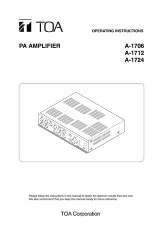
  • 1. OPERATING INSTRUCTIONS PA AMPLIFIER A-1706 A-1712 A-1724 Please follow the instructions in this manual to obtain the optimum results from this unit. We also recommend that you keep this manual handy for future reference.
  • 2. 2 TABLE OF CONTENTS 1. SAFETY PRECAUTIONS ............................................................................... 3 2. GENERAL DESCRIPTION ............................................................................. 4 3. FEATURES .......................................................................................................... 4 4. NOMENCLATURE AND FUNCTIONS Front ......................................................................................................................... 5 Rear .......................................................................................................................... 5 5. CONNECTIONS 5.1. Speaker Connections ........................................................................................ 7 5.2. Remote Volume Control Connection ................................................................. 7 5.3. Remote Power ON/OFF Control Connection .................................................... 7 5.4. External Equipment Connection to the LINE OUT and PWR AMP IN Terminals ................................................. 8 6. FUNCTION SWITCH SETTINGS ................................................................. 8 7. SPEAKER ZONE SELECTION ..................................................................... 8 8. INSTALLATION .................................................................................................. 8 9. RACK MOUNTING ............................................................................................ 9 10. CONTROL SETTINGS ..................................................................................... 9 11. BLOCK DIAGRAM ........................................................................................... 10 12. SPECIFICATIONS ............................................................................................ 11 Accessories ............................................................................................................. 11 Optional products .................................................................................................... 11 13. DIMENSIONAL DIAGRAM ............................................................................ 12
  • 3. 3 1. SAFETY PRECAUTIONS • Be sure to read the instructions in this section carefully before use. • Make sure to observe the instructions in this manual as the conventions of safety symbols and messages regarded as very important precautions are included. • We also recommend you keep this instruction manual handy for future reference. Safety Symbol and Message Conventions Safety symbols and messages described below are used in this manual to prevent bodily injury and property damage which could result from mishandling. Before operating your product, read this manual first and understand the safety symbols and messages so you are thoroughly aware of the potential safety hazards. WARNING Indicates a potentially hazardous situation which, if mishandled, could result in death or serious personal injury. Indicates a potentially hazardous situation which, if mishandled, could result in moderate or minor personal injury, and/or property damage. WARNING CAUTION When Installing the Unit • Do not expose the unit to rain or an environment where it may be splashed by water or other liquids, as doing so may result in fire or electric shock. • Use the unit only with the voltage specified on the unit. Using a voltage higher than that which is specified may result in fire or electric shock. • Do not cut, kink, otherwise damage nor modify the power supply cord. In addition, avoid using the power cord in close proximity to heaters, and never place heavy objects -- including the unit itself -- on the power cord, as doing so may result in fire or electric shock. • Be sure to replace the unit's terminal cover after connection completion. Because high voltage is applied to the speaker terminals, never touch these terminals to avoid electric shock. • Be sure to ground to the safety ground (earth) terminal to avoid electric shock. Never ground to a gas pipe as a catastrophic disaster may result. • Avoid installing or mounting the unit in unstable locations, such as on a rickety table or a slanted surface. Doing so may result in the unit falling down, causing personal injury and/or property damage. • The socket-outlet shall be installed near the equipment and the plug (disconnecting device) shall be easily accessible. When the Unit is in Use • Should the following irregularity be found during use, immediately switch off the power, disconnect the power supply plug from the AC outlet and contact your nearest TOA dealer. Make no further attempt to operate the unit in this condition as this may cause fire or electric shock. · If you detect smoke or a strange smell coming from the unit. · If water or any metallic object gets into the unit · If the unit falls, or the unit case breaks · If the power supply cord is damaged (exposure of the core, disconnection, etc.) · If it is malfunctioning (no tone sounds.) • To prevent a fire or electric shock, never open nor remove the unit case as there are high voltage components inside the unit. Refer all servicing to your nearest TOA dealer. • Do not place cups, bowls, or other containers of liquid or metallic objects on top of the unit. If they accidentally spill into the unit, this may cause a fire or electric shock. • Do not insert nor drop metallic objects or flammable materials in the ventilation slots of the unit's cover, as this may result in fire or electric shock.
  • 4. 4 When Installing the Unit • Never plug in nor remove the power supply plug with wet hands, as doing so may cause electric shock. • When unplugging the power supply cord, be sure to grasp the power supply plug; never pull on the cord itself. Operating the unit with a damaged power supply cord may cause a fire or electric shock. • When moving the unit, be sure to remove its power supply cord from the wall outlet. Moving the unit with the power cord connected to the outlet may cause damage to the power cord, resulting in fire or electric shock. When removing the power cord, be sure to hold its plug to pull. • Do not block the ventilation slots in the unit's cover. Doing so may cause heat to build up inside the unit and result in fire. • Avoid installing the unit in humid or dusty locations, in locations exposed to the direct sunlight, near the heaters, or in locations generating sooty smoke or steam as doing otherwise may result in fire or electric shock. When the Unit is in Use • Do not place heavy objects on the unit as this may cause it to fall or break which may result in personal injury and/or property damage. In addition, the object itself may fall off and cause injury and/or damage. • Make sure that the volume control is set to minimum position before power is switched on. Loud noise produced at high volume when power is switched on can impair hearing. • Do not operate the unit for an extended period of time with the sound distorting. This is an indication of a malfunction, which in turn can cause heat to generate and result in a fire. • Contact your TOA dealer as to the cleaning. If dust is allowed to accumulate in the unit over a long period of time, a fire or damage to the unit may result. • If dust accumulates on the power supply plug or in the wall AC outlet, a fire may result. Clean it periodically. In addition, insert the plug in the wall outlet securely. • Switch off the power, and unplug the power supply plug from the AC outlet for safety purposes when cleaning or leaving the unit unused for 10 days or more. Doing otherwise may cause a fire or electric shock. CAUTION 2. GENERAL DESCRIPTION Equipped with 6 Microphone inputs and 5 AUX inputs (simultaneous use of 9 inputs possible), TOA's A-1706, A-1712, and A-1724 PA Amplifiers are designed to suit PA system applications such as announcements, BGM and broadcasting in mosques, churches, large rooms and factories. 3. FEATURES • Power output of 60 W (A-1706), 120 W (A-1712), and 240 W (A-1724). • All microphone inputs are provided with phantom powering (ON/OFF selectable) and electronically-balanced combined XLR/phone jack connectors. • Convenient 2 zone-selector switches for broadcasting. • An equalizer or other signal processor connectable between PWR AMP IN and LINE OUT terminals to make fine sound adjustment. • Tone controls (bass and treble). • Output level meter. • Master volume control for overall input signal level adjustment. An all-pole mains switch with a contact separation of at least 3 mm in each pole shall be incorporated in the electrical installation of the building.
  • 5. 5 This figure represents the A-1724. 1 3 2 4 56 7 8 9 10 11 4. NOMENCLATURE AND FUNCTIONS [Front] 1. Power switch Press to turn ON the power. Press again to turn the power OFF. Note: The unit is not completely disconnected from the power supply even if this Power switch is turned off. 2. Power indicator Lights green when the power is switched on. 3. Microphone volume controls [MIC 1 – 4] Adjust the microphone level. 4. Microphone/AUX volume controls [MIC 5/AUX 1, MIC 6/AUX 2] Adjust the microphone or AUX level. 5. AUX volume controls [AUX 3 – 5] Adjust the AUX level. 6. Bass control Adjusts bass response. Rotate clockwise to increase bass output, and counterclockwise to reduce it. The center position provides flat characteristics. 7. Treble control Adjusts treble response. Rotate clockwise to increase treble output, and counterclockwise to reduce it. The center position provides flat characteristics. 8. Zone indicators Light to indicate the broadcast zone (zone1, 2) selected with the Zone selector switches. This figure represents the A-1724. 21 22 2312 13 14 15 16 18 1917 20 [Rear]
  • 6. 6 9. Zone selector switches Select the desired broadcast zone. Pressing the ZONE 1 and 2 switches allows the ZONE 1 and 2 output terminals (14) to output signals, respectively. 10. Master volume control Adjusts the overall signal level. 11. LED level meter Indicates an output level. 12. AC inlet Connects to the supplied power cord. 13. Ground terminal A functional ground terminal. 14. Output terminal block Connects to speakers. Outputs signals at the ZONE 1 and 2 output terminals when the front- mounted ZONE 1 and 2 switches (9) are pressed, respectively. The DIRECT output terminal continuously outputs signals irrespective of these switch settings. 15. Recording output terminals [REC OUT] 0 dB, 600 Ω, unbalanced. Output all input signals before the master volume control. Connect a cassette deck, etc. when recording the broadcast contents. 16. Line output terminal [LINE OUT] 0 dB, 600 Ω, unbalanced. Outputs all input signals. Connects to a signal processor such as a limiter or equalizer. (Refer to p. 8.) 17. Power amplifier input terminal [PWR AMP IN] 0 dB, 600 Ω, unbalanced. Accepts output signals from the signal processor connected to the Line output terminal (16). (Refer to p. 8.) Inserting an RCA plug disconnects the internal power amplifier section from the preamplifier section. 18. AUX input terminal [AUX 5] –20 dB, 10 kΩ, unbalanced. A combined XLR (female)/phone jack connector. Accepts external equipment output signals. 19. AUX input terminals [AUX 3, 4] –20 dB, 10 kΩ, unbalanced. Monaural RCA pin jacks. Accept external equipment output signals. 20. Microphone/AUX input terminals [MIC 5/AUX 1, MIC 6/AUX 2] –60 dB, 600 Ω, electronically balanced (MIC 5 and 6) or –20 dB, 600 Ω, electronically balanced (AUX 1 and 2). Combined XLR (female)/phone jack connectors. The input level can be switched between MIC and AUX using the function switch (23). 21. Microphone input terminals [MIC 1 – 4] –60 dB, 600 Ω, electronically balanced. Combined XLR (female)/phone jack connectors. Note Use an XLR connector when connecting a phantom-powered microphone to this terminal. Using a phone plug instead may cause a noise if it is touched or rotated. 22. Remote control terminal block (1) Remote power ON/OFF control input [POWER REMOTE] Allows remote control of the unit's power ON/OFF. No-voltage make contact input. (2) Remote volume control [REMOTE VOLUME] Connecting a 10 kΩ linear taper volume control across these terminals will allow remote control of Line output and speaker output levels. 23. Function switch An 8-bit DIP switch. Selects the following functions: (1) Phantom power ON/OFF for each MIC 1–6 (2) Input sensitivity for MIC 5/AUX 1 and MIC 6/AUX 2 Refer to p. 8 "FUNCTION SWITCH SETTINGS" for details. Usable connectors and plugs • XLR type male connector • Phone plug Pin 1: Ground Sleeve: Ground Pin 2: Hot Tip: HotPin 3: Cold Ring: Cold
  • 7. Be sure to attach the supplied terminal cover after connection completion. Because high voltage is applied to the speaker terminals, never touch these terminals to avoid electric shock. 7 5. CONNECTIONS 5.1. Speaker Connections C C 4 16Ω DIRECT 100 V ZONE 2 100 V ZONE 1 100 V C C 4 16Ω DIRECT 100 V ZONE 2 100 V ZONE 1 100 V Total impedance 167 Ω (A-1706) 83 Ω (A-1712) 42 Ω (A-1724) 4 – 16 Ω 100 V line 100 V line 100 V line Notes • Both the 4 – 16 Ω and 100 V terminals cannot be used at the same time. • Impedances indicated in the figures represent the total speaker system (load) impedances. WARNING 5.2. Remote Volume Control Connection REMOTE VOLUME POWER REMOTE HC Volume control 10 kΩThe volume control allows remote adjustment of the post-master volume signals. When performing the remote volume control, adjust the master volume control in advance noting that its setting limits the maximum signal level adjustable with the volume control. Be sure to avoid turning fully down the master volume control. 5.3. Remote Power ON/OFF Control Connection REMOTE VOLUME POWER REMOTE HC With the unit's power switched OFF, shorting the POWER REMOTE terminals can remotely turn it ON. With ON, the power cannot be remotely controlled.
  • 8. Phantom Power Over 10 cmOver 10 cm Over 10 cm 8 6. FUNCTION SWITCH SETTINGS Set the rear-mounted Function switch as shown below. 7. SPEAKER ZONE SELECTION Pressing the front-mounted ZONE 1 switch permits its zone indicator to light and makes broadcast through the speakers connected to the rear-mounted Zone 1 output terminals. Operation for ZONE 2 is performed in the same way as above. 8. INSTALLATION Keep the unit's all sides over 10 cm away from objects that may obstruct air flow to prevent the unit's internal temperature rise. 1 2 ON 3 4 5 6 7 8 Switch No. Function OFF ON 1 MIC 6/AUX 2 MIC 6 AUX 2 2 MIC 5/AUX 1 MIC 5 AUX 1 3 MIC 6 OFF ON 4 MIC 5 OFF ON 5 MIC 4 OFF ON 6 MIC 3 OFF ON 7 MIC 2 OFF ON 8 MIC 1 OFF ON 5.4. External Equipment Connection to the LINE OUT and PWR AMP IN Terminals A-1700 series Equalizer, limiter, etc. By connecting a signal processor such as an equalizer or limiter between the preamplifier section (LINE OUT) and the power amplifier section (PWR AMP IN) of the A-1700 series, signals can be tailored for desired sound output. Note Inserting an RCA plug into the PWR AMP IN terminal disconnects the internal power amplifier section from the preamplifier section.
  • 9. 9 9. RACK MOUNTING To mount the unit in a standard 19" equipment rack, use the optional MB-25B Rack Mounting Bracket. Attach the MB-25B to the unit using the supplied 4 screws. When using other screws, each screw must be shorter than 16 mm. MB-25B M4 x 16 Machine screw included in MB-25B Amplifiers PF-013B (optional) Note Use the optional PF-013B Perforated Panels to provide sufficient ventilation when mounting 2 or more units in an equipment rack. 10. CONTROL SETTINGS Output levels are adjustable with individual volume controls. For music play or announcements, adjust the corresponding volume control so that the red indicator doesn't light. Note that the sound quality is downgraded when the red indicator remains lit. To prevent the accidental change of the settings of input volume and tone (Bass and Treble) controls, remove their knobs after setting them to the desired position and attach the optional YA-920 Volume Control Covers instead. MIC 1 BASS MIC 2 YA-920 (optional) Control knob
  • 10. 10 11. BLOCK DIAGRAM + + + + + + 87654321 AUX4 –20dB/10kΩ AUX3 –20dB/10kΩ MIC6 –60dB/600Ω AUX2 –20dB/600Ω MIC5 –60dB/600Ω AUX1 –20dB/600Ω MIC4 –60dB/600Ω MIC3 –60dB/600Ω MIC2 –60dB/600Ω MIC1 –60dB/600Ω AUX5 –20dB/10kΩ POWER REMOTE REMOTE VOLUME + – H C (70V) 240V 230V VCA Relay2Relay1 Power remote EB EB EB EB EB EB PA ON POWER switch Powerfor controlsection Powerfor audiosection Thermal sensor Fan 240Wonly ZONE2ZONE1 ZONE1(100V) ZONE2(100V) Zone2Zone1 POWER 220–230VAC or240VAC, 50/60Hz A-1712andA-1724only PT FuseFuse Output levelmeter (Relay2) (Relay1) JP OT DIRECT(100V) 4–16Ω C C RECOUT 0dB LINEOUT,0dB/600Ω PWRAMPIN,600Ω 0dB–20dB–20dB –20dB –20dB –20dB –20dB –20dB –20dB –20dB BASS/TREBLE MASTER volume PhantompowerON/OFF Phantom power Sensitivityselection Functionswitch(DIPswitch) Sensitivityselection Sensitivity selection
  • 11. 11 12. SPECIFICATIONS Model No. A-1706 A-1712 A-1724 Power Source 220 – 230 V AC or 240 V AC, 50/60 Hz Rated Output 60 W 120 W 240 W Power/Current Consumption 150 W (rated output), 258 W (rated output), 532 W (rated output), 60 W (EN60065) 105 W (EN60065) 220 W (EN60065) Under 150 mA (when Under 320 mA (when Under 60 mA (when power switch is OFF) power switch is OFF) power switch is OFF) Frequency Response 50 – 20,000 Hz (±3 dB) Distortion Under 2% at 1 kHz, rated power Input MIC 1 – 6: –60 dB*1, 600 Ω, electronically-balanced, combined type of XLR-3-31 equivalent and phone jack AUX 1 – 2: –20 dB*1, 600 Ω, electronically-balanced, combined type of XLR-3-31 equivalent and phone jack (Either MIC 5 or AUX 1, and either MIC 6 or AUX 2 selectable) AUX 3 – 4: –20 dB*1, 10 kΩ, unbalanced, RCA pin jack AUX 5: –20 dB*1, 10 kΩ, unbalanced, combined type of XLR-3-31 equivalent and phone jack PWR AMP IN: 0 dB*1, 600 Ω, unbalanced, RCA pin jack (An equalizer or other signal processor connectable between LINE OUT and PWR AMP IN terminals) Output REC: 0 dB*1, 600 Ω, unbalanced, RCA pin jack LINE: 0 dB*1, 600 Ω, unbalanced, RCA pin jack SPEAKER SELECTOR: 2 zone, high impedance*2 (100 V line), individual selector key, M4 screw terminal*3 DIRECT SPEAKER OUT: High impedance*2 (100 V line), M4 screw terminal*3, Low impedance (4 – 16 Ω), M4 screw terminal*3 Note: Both Low and High impedance terminals cannot be used at the same time. Phantom Power ON or OFF for each MIC 1 – 6 with switch setting S/N Ratio Over 100 dB (Master volume: min) (Band Pass: 20 – 20,000 Hz) Over 76 dB (Master volume: max) Over 60 dB (MIC 1 – MIC 4) Over 53 dB (MIC 5, MIC 6) Over 76 dB (AUX 1 – AUX 5) Tone Control Bass: ±10 dB at 100 Hz, Treble: ±10 dB at 10 kHz Control Input REMOTE VOLUME: M3 screw terminal*3 POWER REMOTE: No-voltage make contact input Open voltage: 28 V DC (when the unit's power is OFF) Short-circuit: Under 10 mA, M3 screw terminal*3 Indicator 5-point LED output level meter, Power indicator LED, Zone indicator LEDs Operating Temperature –10°C to +40°C Finish Panel: ABS resin, black, hair line Case: Steel plate, black Dimensions 420 (w) x 107.7 (h) x 367 (d) mm Weight 9.3 kg 12.6 kg 13.5 kg *1 0 dB = 1 V *2 167 Ω (A-1706), 83 Ω (A-1712), 42 Ω (A-1724) *3 Distance between barriers on the above screw terminals: 7 mm (M3 screw), 9 mm (M4 screw) Note: The design and specifications are subject to change without notice for improvement. • Accessories AC power cord ................................................. 1 Terminal cover ................................................. 1 Terminal cover mounting screw (M4 x 8) ......... 2 • Optional products Rack mounting bracket: MB-25B Volume control cover: YA-920 Perforated panel: PF-013B
  • 12. 13. DIMENSIONAL DIAGRAM (Applicable to all models) 107.7 88.4 Unit: mm 367420 326.518.5 133-12-845-5C URL: http://www.toa.jp/ Traceability Information for Europe (EMC directive 2004/108/EC) Manufacturer: TOA Corporation 7-2-1, Minatojima Nakamachi, Chuo-ku, Kobe, Hyogo, Japan Authorized representative: TOA Electronics Europe GmbH Suederstrasse 282, 20537 Hamburg, Germany