SlideShare a Scribd company logo
1 of 7
CASE STUDY
AIM:
To check the structural design of roof of shuttle kiln using shear force and bending moment diagram.
TO FIND:
1. Maximum bending stress on ‘I’ beam
2. Maximum deflection of ‘I’ beam
3. Linear expansion of the I beam @ 150 Deg.C
SOLUTION:
As per the structural design I beams carry major loads where as other L angles are used for stiffening
purpose. Let us consider single I beam at the middle of the roof for design. This I beam carries the load of
structural members and ceramic fiber modules in the distance of 1500mm.
Let us say, ‘I’ beam acts as a simply supported beam with uniform distributed load. Hence, let us determine
the load acting on the ‘I’ Beam.
Load Acting on the ‘I’ beam:
a) Plate - 1.5m x 3.75m x .005 x 7850 = 220 Kg
b) Double L angle - 7.7 Kg x 5 x 1.5m x 2 = 115 Kg
c) Single L angle - 7.7 Kg x 3.75m = 30 Kg
d) Pyrobloc/ Blanket - for the area of 1.5 x 3.75m = 620 Kg
----------------------------------
Total Mass acting on the beam = 985 Kg
------------------------------------
Weight acting on the beam = 985 x 9.81 N
= 9662.85 N
Weight acting per meter of the Beam = 9662.85/3.75 N/m
Weight acting per meter of the Beam = 2576 N/m
www.morganthermalceramics.com
Company Registration Number: 18-9622, Registered Office: Dare House Complex, No.2, N.S.C. Bose Road, Chennai – 600 001. INDIA
Shear force and bending moment diagram:
From the above diagram, a simply supported beam with load has two reactions RA & RB at both ends.
To find out the reactions RA & RB, following equation has to be resolved.
From the above diagram,
www.morganthermalceramics.com
Company Registration Number: 18-9622, Registered Office : Dare House Complex, No.2, N.S.C. Bose Road, Chennai – 600 001. INDIA
Summation of reactions is zero.
∑R = 0
RA +RB = 2576 x 3.75
RA +RB = 9660 -------------- (1)
From the above diagram,
Summation of bending moment about point A is zero.
∑MA = 0
RB x 3.75 – [2576 x 3.75 x 3.75/2] = 0 ---------------- (2)
RB = 18112.5/ 3.75
RB=4830 N
Substitute this value in Eqn.1
Therefore,
RA = 4830 N
From these result we can draw the shear force diagram. Shear force diagram clearly depicts that max shear
force will be at the both end of I beam and zero at the mid of I beam.
The formula for calculation max. bending moment of simply supported beam having uniform distributed
load is,
M max = wl2
/8
Where,
M max - Max. Bending moment (Nm)
w – Load per unit length (N/m)
l - Length of the I beam (m)
M max = 2576 x 3.75 x3.75/ 8
M max =4528 Nm
As we known, bending moment will be max, at the point where shear force is zero. Hence, the max.
bending will happen only at the middle of the beam.
Calculation of bending stress:
Max. bending stress acting at the middle of I beam can be calculated by means of bending equation.
M/I = σb/y = E/R
Here,
www.morganthermalceramics.com
Company Registration Number: 18-9622, Registered Office : Dare House Complex, No.2, N.S.C. Bose Road, Chennai – 600 001. INDIA
M - Max. bending moment (Nm)
I - Moment of inertia (m4
) (Ixx = 2235.4 x 10-8
m4
)
σb - Bending stress (N/m2
)
y - Distance between neutral axis to extreme fiber (m) [ for ISMB 200 x 100, Y = 100mm)
Hence,
σb = M x y/I (N/m2)
= 4528 x 0.1/ (2235.4 x 10-8)
= 20.25 MN/ m2
σb = 20.25 N/mm2
Calculation of Allowable stress:
Let us consider, factor of safety as 4. Yield strength of structural steel is 250 N/mm2
Allowable stress = Yield strength/ FOS
= 250/4
Allowable stress = 62.5 N/mm2
From the above results, it is very clear bending stress is three times less than allowable stress. Hence our
design is in safe side. i.e., σb < Allowable stress.
Here we need to consider temperature as a factor as it is affecting the performance of the beam. Let us
consider the max. cold face temperature is 150Deg.C.
Hence we need to calculate the yield strength of the beam at 150 Deg.C.
We know,
E (young’s modulus) = yield stress / strain and formula for coefficient of thermal expansion is,
ά = [Δl/ LxΔT]
Here, Δl – change in length (m)
L – Length of the beam (m)
ΔT – change in temperature (Deg.C)
The above eqn. can be written like this,
ά x ΔT = [Δl/ L] = Strain
Incorporate this formula in young’s modulus formula,
Yield Stress = ά x ΔT x E
= 11 x 10-6
x (150 – 40) x 200 x 109
= 242 106
N/m2
www.morganthermalceramics.com
Company Registration Number: 18-9622, Registered Office : Dare House Complex, No.2, N.S.C. Bose Road, Chennai – 600 001. INDIA
Yield stress = 242 N/mm2
Now, let us calculate the allowable stress again for this value.
Allowable stress = Yield strength @ 150 Deg.C/ FOS
= 242/4
Allowable stress = 60.5 N/mm2
From the above result we can say, σb < Allowable stress.
Calculation of deflection of beams:
Formula to compute the Max. deflection of simply supported beam having uniform distributed load is,
Max. deflection = (5/384) x (wl4
/ EI) (m)
Here,
w – Load per unit length (N/m)
l - Length of the I beam (m)
E - Young’s modulus = 206842 x 106
N/m2
I - Moment of inertia (m4) (Ixx = 2235.4 x 10-8
m4
)
Max. deflection = (5/384) x (2576 x 3.754
)/(206842 x106
x 2235 x10-8
)
Max. deflection = 1.4348 x 10⁻³
m
Max. deflection =1.4348 mm
Consideration of linear thermal expansion:
Δl = ά x LxΔT
= 11x10-6
x 3750 x (150-40)
Δl = 4.5 mm
Hence, as per the above result we need to maintain 2.25mm expansion gap on the both side of the beam.
Result:
1. Maximum bending stress is less than allowable stress @ 150 Deg.C; hence design is in safer side.
2. Beam deflection is apprx. 1.5mm and it is negligible.
3. Linear Expansion of 2.25mm has to be considered on both the side of the I beam.
Reference:
• Structural drawing 10224801 R1
www.morganthermalceramics.com
Company Registration Number: 18-9622, Registered Office : Dare House Complex, No.2, N.S.C. Bose Road, Chennai – 600 001. INDIA
• Hand book for structural engineers – Bureau of Indian standards SP: 6(1)-1964 revised 1998
• Strength of Materials - Dr.R.K. Bansal
www.morganthermalceramics.com
Company Registration Number: 18-9622, Registered Office : Dare House Complex, No.2, N.S.C. Bose Road, Chennai – 600 001. INDIA
• Hand book for structural engineers – Bureau of Indian standards SP: 6(1)-1964 revised 1998
• Strength of Materials - Dr.R.K. Bansal
www.morganthermalceramics.com
Company Registration Number: 18-9622, Registered Office : Dare House Complex, No.2, N.S.C. Bose Road, Chennai – 600 001. INDIA

More Related Content

What's hot

M E C H A N I C S O F S O L I D S J N T U M O D E L P A P E R{Www
M E C H A N I C S  O F  S O L I D S  J N T U  M O D E L  P A P E R{WwwM E C H A N I C S  O F  S O L I D S  J N T U  M O D E L  P A P E R{Www
M E C H A N I C S O F S O L I D S J N T U M O D E L P A P E R{Www
guest3f9c6b
 

What's hot (19)

22564 emd 1.9 numericals
22564 emd 1.9 numericals22564 emd 1.9 numericals
22564 emd 1.9 numericals
 
Deflection of simply supported beam and cantilever
Deflection of simply supported beam and cantileverDeflection of simply supported beam and cantilever
Deflection of simply supported beam and cantilever
 
Structural analysis II by moment-distribution CE 313,turja deb mitun id 13010...
Structural analysis II by moment-distribution CE 313,turja deb mitun id 13010...Structural analysis II by moment-distribution CE 313,turja deb mitun id 13010...
Structural analysis II by moment-distribution CE 313,turja deb mitun id 13010...
 
18-Beam Column Strength (Steel Structural Design & Prof. Shehab Mourad)
18-Beam Column Strength (Steel Structural Design & Prof. Shehab Mourad)18-Beam Column Strength (Steel Structural Design & Prof. Shehab Mourad)
18-Beam Column Strength (Steel Structural Design & Prof. Shehab Mourad)
 
12-Examples on Compression Members (Steel Structural Design & Prof. Shehab Mo...
12-Examples on Compression Members (Steel Structural Design & Prof. Shehab Mo...12-Examples on Compression Members (Steel Structural Design & Prof. Shehab Mo...
12-Examples on Compression Members (Steel Structural Design & Prof. Shehab Mo...
 
M E C H A N I C S O F S O L I D S J N T U M O D E L P A P E R{Www
M E C H A N I C S  O F  S O L I D S  J N T U  M O D E L  P A P E R{WwwM E C H A N I C S  O F  S O L I D S  J N T U  M O D E L  P A P E R{Www
M E C H A N I C S O F S O L I D S J N T U M O D E L P A P E R{Www
 
temperature stresses in Strength of materials
temperature stresses in Strength of materialstemperature stresses in Strength of materials
temperature stresses in Strength of materials
 
Numericals on Columns and struts_-_solved
Numericals on Columns and struts_-_solvedNumericals on Columns and struts_-_solved
Numericals on Columns and struts_-_solved
 
22564 emd 1.2 numericals
22564 emd 1.2 numericals22564 emd 1.2 numericals
22564 emd 1.2 numericals
 
22-Design of Four Bolt Extended Endplate Connection (Steel Structural Design ...
22-Design of Four Bolt Extended Endplate Connection (Steel Structural Design ...22-Design of Four Bolt Extended Endplate Connection (Steel Structural Design ...
22-Design of Four Bolt Extended Endplate Connection (Steel Structural Design ...
 
C09 m-403032016 som
C09 m-403032016 somC09 m-403032016 som
C09 m-403032016 som
 
BENDING STRESS IN A BEAMS
BENDING STRESS IN A BEAMSBENDING STRESS IN A BEAMS
BENDING STRESS IN A BEAMS
 
22564 emd 2.1 cotter joint numerical
22564 emd 2.1 cotter joint numerical 22564 emd 2.1 cotter joint numerical
22564 emd 2.1 cotter joint numerical
 
13-Effective Length of Columns (Steel Structural Design & Prof. Shehab Mourad)
13-Effective Length of Columns (Steel Structural Design & Prof. Shehab Mourad)13-Effective Length of Columns (Steel Structural Design & Prof. Shehab Mourad)
13-Effective Length of Columns (Steel Structural Design & Prof. Shehab Mourad)
 
22564 emd 2.0 design of joints, lever, offset links
22564 emd 2.0 design of joints, lever, offset links22564 emd 2.0 design of joints, lever, offset links
22564 emd 2.0 design of joints, lever, offset links
 
Doubly reinforced beam design
Doubly reinforced beam   designDoubly reinforced beam   design
Doubly reinforced beam design
 
Design of Machine Elements - Unit 3 Procedures
 Design of Machine Elements - Unit 3 Procedures Design of Machine Elements - Unit 3 Procedures
Design of Machine Elements - Unit 3 Procedures
 
4 static shear
4  static shear4  static shear
4 static shear
 
7 fatigue
7  fatigue7  fatigue
7 fatigue
 

Similar to CASE STUDY - STRUCTURAL DESIGN FOR MODERN INSULATOR'S SHUTTLE KILN ROOF

Design ppt
Design pptDesign ppt
Design ppt
tishu001
 
1. simple stress_strain
1. simple stress_strain1. simple stress_strain
1. simple stress_strain
amitsomwanshi
 
INDUSTRIAL BUILDING GANTRY GIRDER
INDUSTRIAL BUILDING  GANTRY GIRDERINDUSTRIAL BUILDING  GANTRY GIRDER
INDUSTRIAL BUILDING GANTRY GIRDER
Harsh Shani
 
Episode 39 : Hopper Design
Episode 39 :  Hopper Design Episode 39 :  Hopper Design
Episode 39 : Hopper Design
SAJJAD KHUDHUR ABBAS
 

Similar to CASE STUDY - STRUCTURAL DESIGN FOR MODERN INSULATOR'S SHUTTLE KILN ROOF (20)

Design ppt
Design pptDesign ppt
Design ppt
 
Bending stresses
Bending stressesBending stresses
Bending stresses
 
Shear Force
Shear ForceShear Force
Shear Force
 
1. simple stress_strain
1. simple stress_strain1. simple stress_strain
1. simple stress_strain
 
stress_strain SS ramamrutham.ppt
stress_strain SS ramamrutham.pptstress_strain SS ramamrutham.ppt
stress_strain SS ramamrutham.ppt
 
presentation1_28.pptx
presentation1_28.pptxpresentation1_28.pptx
presentation1_28.pptx
 
MEC2402 Stress Analysis.docx
MEC2402 Stress Analysis.docxMEC2402 Stress Analysis.docx
MEC2402 Stress Analysis.docx
 
Selecting Columns And Beams
Selecting Columns And BeamsSelecting Columns And Beams
Selecting Columns And Beams
 
diff_bwt_is_800_101.ppt
diff_bwt_is_800_101.pptdiff_bwt_is_800_101.ppt
diff_bwt_is_800_101.ppt
 
Prestress loss due to friction & anchorage take up
Prestress loss due to friction & anchorage take upPrestress loss due to friction & anchorage take up
Prestress loss due to friction & anchorage take up
 
INDUSTRIAL BUILDING GANTRY GIRDER
INDUSTRIAL BUILDING  GANTRY GIRDERINDUSTRIAL BUILDING  GANTRY GIRDER
INDUSTRIAL BUILDING GANTRY GIRDER
 
Mm207 group 9 numericals
Mm207 group 9 numericalsMm207 group 9 numericals
Mm207 group 9 numericals
 
PLASTIC BEAM in design of stell beam design
PLASTIC BEAM in design of stell beam designPLASTIC BEAM in design of stell beam design
PLASTIC BEAM in design of stell beam design
 
SolidWorks Assignment Help.pptx
SolidWorks Assignment Help.pptxSolidWorks Assignment Help.pptx
SolidWorks Assignment Help.pptx
 
Beginner's idea to Computer Aided Engineering - ANSYS
Beginner's idea to Computer Aided Engineering - ANSYSBeginner's idea to Computer Aided Engineering - ANSYS
Beginner's idea to Computer Aided Engineering - ANSYS
 
Compression member
Compression memberCompression member
Compression member
 
Guntry girder
Guntry girderGuntry girder
Guntry girder
 
Episode 39 : Hopper Design
Episode 39 :  Hopper Design Episode 39 :  Hopper Design
Episode 39 : Hopper Design
 
Footing design
Footing designFooting design
Footing design
 
Design of dual axis tracker wps
Design of dual axis tracker wpsDesign of dual axis tracker wps
Design of dual axis tracker wps
 

More from Rituraj Dhar (11)

HPCL SINGLE LINE DIAGRAM LONI DISPATCH TERMINAL
HPCL SINGLE LINE DIAGRAM LONI DISPATCH TERMINALHPCL SINGLE LINE DIAGRAM LONI DISPATCH TERMINAL
HPCL SINGLE LINE DIAGRAM LONI DISPATCH TERMINAL
 
Swiss knife
Swiss knifeSwiss knife
Swiss knife
 
Swiss knife
Swiss knifeSwiss knife
Swiss knife
 
SWISS KNIFE MODEL
SWISS KNIFE MODELSWISS KNIFE MODEL
SWISS KNIFE MODEL
 
SWISS KNIFE
SWISS KNIFESWISS KNIFE
SWISS KNIFE
 
SWISS KNIFE
SWISS KNIFESWISS KNIFE
SWISS KNIFE
 
Rituraj-Model 1
Rituraj-Model 1Rituraj-Model 1
Rituraj-Model 1
 
edm
edmedm
edm
 
FINAL2
FINAL2FINAL2
FINAL2
 
gear
geargear
gear
 
ANTI-LOCK BRAKES
ANTI-LOCK BRAKESANTI-LOCK BRAKES
ANTI-LOCK BRAKES
 

CASE STUDY - STRUCTURAL DESIGN FOR MODERN INSULATOR'S SHUTTLE KILN ROOF

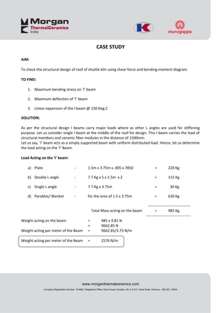
  • 1. CASE STUDY AIM: To check the structural design of roof of shuttle kiln using shear force and bending moment diagram. TO FIND: 1. Maximum bending stress on ‘I’ beam 2. Maximum deflection of ‘I’ beam 3. Linear expansion of the I beam @ 150 Deg.C SOLUTION: As per the structural design I beams carry major loads where as other L angles are used for stiffening purpose. Let us consider single I beam at the middle of the roof for design. This I beam carries the load of structural members and ceramic fiber modules in the distance of 1500mm. Let us say, ‘I’ beam acts as a simply supported beam with uniform distributed load. Hence, let us determine the load acting on the ‘I’ Beam. Load Acting on the ‘I’ beam: a) Plate - 1.5m x 3.75m x .005 x 7850 = 220 Kg b) Double L angle - 7.7 Kg x 5 x 1.5m x 2 = 115 Kg c) Single L angle - 7.7 Kg x 3.75m = 30 Kg d) Pyrobloc/ Blanket - for the area of 1.5 x 3.75m = 620 Kg ---------------------------------- Total Mass acting on the beam = 985 Kg ------------------------------------ Weight acting on the beam = 985 x 9.81 N = 9662.85 N Weight acting per meter of the Beam = 9662.85/3.75 N/m Weight acting per meter of the Beam = 2576 N/m www.morganthermalceramics.com Company Registration Number: 18-9622, Registered Office: Dare House Complex, No.2, N.S.C. Bose Road, Chennai – 600 001. INDIA
  • 2. Shear force and bending moment diagram: From the above diagram, a simply supported beam with load has two reactions RA & RB at both ends. To find out the reactions RA & RB, following equation has to be resolved. From the above diagram, www.morganthermalceramics.com Company Registration Number: 18-9622, Registered Office : Dare House Complex, No.2, N.S.C. Bose Road, Chennai – 600 001. INDIA
  • 3. Summation of reactions is zero. ∑R = 0 RA +RB = 2576 x 3.75 RA +RB = 9660 -------------- (1) From the above diagram, Summation of bending moment about point A is zero. ∑MA = 0 RB x 3.75 – [2576 x 3.75 x 3.75/2] = 0 ---------------- (2) RB = 18112.5/ 3.75 RB=4830 N Substitute this value in Eqn.1 Therefore, RA = 4830 N From these result we can draw the shear force diagram. Shear force diagram clearly depicts that max shear force will be at the both end of I beam and zero at the mid of I beam. The formula for calculation max. bending moment of simply supported beam having uniform distributed load is, M max = wl2 /8 Where, M max - Max. Bending moment (Nm) w – Load per unit length (N/m) l - Length of the I beam (m) M max = 2576 x 3.75 x3.75/ 8 M max =4528 Nm As we known, bending moment will be max, at the point where shear force is zero. Hence, the max. bending will happen only at the middle of the beam. Calculation of bending stress: Max. bending stress acting at the middle of I beam can be calculated by means of bending equation. M/I = σb/y = E/R Here, www.morganthermalceramics.com Company Registration Number: 18-9622, Registered Office : Dare House Complex, No.2, N.S.C. Bose Road, Chennai – 600 001. INDIA
  • 4. M - Max. bending moment (Nm) I - Moment of inertia (m4 ) (Ixx = 2235.4 x 10-8 m4 ) σb - Bending stress (N/m2 ) y - Distance between neutral axis to extreme fiber (m) [ for ISMB 200 x 100, Y = 100mm) Hence, σb = M x y/I (N/m2) = 4528 x 0.1/ (2235.4 x 10-8) = 20.25 MN/ m2 σb = 20.25 N/mm2 Calculation of Allowable stress: Let us consider, factor of safety as 4. Yield strength of structural steel is 250 N/mm2 Allowable stress = Yield strength/ FOS = 250/4 Allowable stress = 62.5 N/mm2 From the above results, it is very clear bending stress is three times less than allowable stress. Hence our design is in safe side. i.e., σb < Allowable stress. Here we need to consider temperature as a factor as it is affecting the performance of the beam. Let us consider the max. cold face temperature is 150Deg.C. Hence we need to calculate the yield strength of the beam at 150 Deg.C. We know, E (young’s modulus) = yield stress / strain and formula for coefficient of thermal expansion is, ά = [Δl/ LxΔT] Here, Δl – change in length (m) L – Length of the beam (m) ΔT – change in temperature (Deg.C) The above eqn. can be written like this, ά x ΔT = [Δl/ L] = Strain Incorporate this formula in young’s modulus formula, Yield Stress = ά x ΔT x E = 11 x 10-6 x (150 – 40) x 200 x 109 = 242 106 N/m2 www.morganthermalceramics.com Company Registration Number: 18-9622, Registered Office : Dare House Complex, No.2, N.S.C. Bose Road, Chennai – 600 001. INDIA
  • 5. Yield stress = 242 N/mm2 Now, let us calculate the allowable stress again for this value. Allowable stress = Yield strength @ 150 Deg.C/ FOS = 242/4 Allowable stress = 60.5 N/mm2 From the above result we can say, σb < Allowable stress. Calculation of deflection of beams: Formula to compute the Max. deflection of simply supported beam having uniform distributed load is, Max. deflection = (5/384) x (wl4 / EI) (m) Here, w – Load per unit length (N/m) l - Length of the I beam (m) E - Young’s modulus = 206842 x 106 N/m2 I - Moment of inertia (m4) (Ixx = 2235.4 x 10-8 m4 ) Max. deflection = (5/384) x (2576 x 3.754 )/(206842 x106 x 2235 x10-8 ) Max. deflection = 1.4348 x 10⁻³ m Max. deflection =1.4348 mm Consideration of linear thermal expansion: Δl = ά x LxΔT = 11x10-6 x 3750 x (150-40) Δl = 4.5 mm Hence, as per the above result we need to maintain 2.25mm expansion gap on the both side of the beam. Result: 1. Maximum bending stress is less than allowable stress @ 150 Deg.C; hence design is in safer side. 2. Beam deflection is apprx. 1.5mm and it is negligible. 3. Linear Expansion of 2.25mm has to be considered on both the side of the I beam. Reference: • Structural drawing 10224801 R1 www.morganthermalceramics.com Company Registration Number: 18-9622, Registered Office : Dare House Complex, No.2, N.S.C. Bose Road, Chennai – 600 001. INDIA
  • 6. • Hand book for structural engineers – Bureau of Indian standards SP: 6(1)-1964 revised 1998 • Strength of Materials - Dr.R.K. Bansal www.morganthermalceramics.com Company Registration Number: 18-9622, Registered Office : Dare House Complex, No.2, N.S.C. Bose Road, Chennai – 600 001. INDIA
  • 7. • Hand book for structural engineers – Bureau of Indian standards SP: 6(1)-1964 revised 1998 • Strength of Materials - Dr.R.K. Bansal www.morganthermalceramics.com Company Registration Number: 18-9622, Registered Office : Dare House Complex, No.2, N.S.C. Bose Road, Chennai – 600 001. INDIA