
Empfohlen
Weitere ähnliche Inhalte
Was ist angesagt?
Was ist angesagt? (20)
Ähnlich wie Art of Thread Design
Ähnlich wie Art of Thread Design (20)
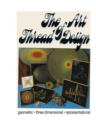
Art of Thread Design
- 1. geometric • three dimensional • representational
- 2. written by mark jansen appendix by f.e. barline, jr. designed and illustrated by fred fortune
- 3. As the popularity of thread design spreads throughout the world, I am continually impressed with the endless artistic variations possible with the use of colored sewing thread. Some of these variations are presented in this book. More important, however, are the basic theory and techniques explained here in simple language and with which the most spectacular thread design masterpieces are created. I wish the reader a stimulating and enjoyable excursion into this challenging medium. Mark Jansen Campbell, California March, 1974 introduction The use of colored thread as a medium in art has become the source of a whole new wave of craft innovations. This booklet deals with the most dramatic of these recent applications, known as Mandala® geometric thread design. "Mandala" is an ancient word from the Far East, used in the context of transcendental meditation. It is vague in meaning, but refers to a visual pattern which draws a viewer's attention into its center. The original mandalas were great paintings of objects arranged in circles, the effect of this symmetry being to minimize the influence of unwanted distraction. This same function is inherent in the patterns shown throughout these pages and is why the name "Mandala" was chosen to identify this new art form. The unique feature of Mandala* geometric thread design lies in the fact that each pattern is a set of points, called vertices, located very carefully on a closed conic curve such as a circle or an ellipse. The vertices are then connected with straight lines according to a strict numerical progression, resulting in an impressive finished thread design. The formation of curved lines from straight ones can be understood by considering the idea of a tangent. In the case of a circle, any straight line which touches the circle at exactly one point is called a tangent. A tangent can be drawn at any point along any arbitrary curve as long as the curve is smooth (doesn't have an end point or sharp corner) at that point. Simply stated, this means that any curve may be thought of as the intersection of infinitely many tangents. From this geometrical idea, it is quite natural to see how curved patterns can be defined with suitably arranged straight lines. Let us look at two fairly simple illustrations of this proposal. In the first drawing below, you see a right angle whose legs have been equally subdivided. When straight lines are drawn between the resulting points as shown, a hyperbolic curve is formed. The third drawing shows a circle with equidistant points located around its circumference. If a set of equally long line segments is used to connect these points, a small circle appears, defined by tangents! Note that it is the placement of the outside points, called vertices or generating points, which determines the contour of the resulting curve. Notice in the circular example that the generating points could have been connected with a different set of lines. The number of points skipped between connected points could have been four, or six, as well as five. Consider the effect of superimposing different straight line combinations drawn from the same set of generating points, each defining a different inner circle. The separate combinations then become circular Mandala™ layers.
- 5. one two three sum In general, for N generating points in a circle, the number of ways to connect all the points with lines of equal length is equal to N/2 if N is even or (N - 1)/2 if N is odd. This means that in the example, there are (47 - 1)/2 = 23 possible layers. circular, elliptical, and starburst designs As shown previously, it is the arrangement of generating points which determines the shape of each design. In this section, we will show how these points are accurately located for each of the three basic patterns shown and how the resulting points are threaded. Designing A Circular Template Needed for laying out a precise template are a sharp pencil, paper, a ruler, some string, a hammer, nail, a flat board, and a compass. With these tools anyone can geometrically construct the set of generating points for circular, elliptical and starburst geometric thread designs. Let's look at the simplest case and consider the steps for drawing a circular template: 1, Cut a piece of paper square to the desired size of background. Locate the center of the square by drawing diagonal lines connecting opposite corners. The two diagonals intersect at the center point, which will eventually be the center of the circular design. 2, Draw a circle using a small nail driven into the center point and a piece of string set to the radius of the desired circle. 3, Subdivide the circle into a prime number of equal parts. A prime number has no divisors other than one and itself, like 11, 41, 67, and 101. With a prime number of generating points, each layer in the design can be made with one continuous strand of thread, lied off neatly only where the ends meet. See Appendix A for more on prime numbers. As outlined above, constructing a circular template is fairly simple. You should take care, however, in completing each step. The accuracy, for instance, of finding the center point and drawing a circle will determine how well the finished design is centered.
- 7. Once a prime number has been chosen for the number of vertices, the circle must be divided into that many equal divisions. This is done with the dividers, or a compass, and is the most critical step in drawing an accurate template. Start by calculating the distance between points by dividing the circumference of your circle by the number of vertices you desire. Set the distance of your dividers tc equal this distance and walk them around the circle. Walking the dividers set at this calculated distance around the circle will tell you how close your initial setting is to the exact one. Ideally, travelir once around the circle should bring the point of the dividers right back to the first mark. This rarely happens on the first trial, but repeated adjustments of the divider setting will lead eventually to an equidistant set of points. The circumference "C" of a circle with radius r is given by C = 2^r «* 6.3r. When the correct setting is found, each indicated point should be marked on the template, as shown above Check to make sure the total number of marks is equal to the number expected! It's easy to leave one out or add one extra without noticing. After the divisions are marked and double checked, the template is finished. Threading A Circular Design The theory of threading a Mandala® geometric thread design is simpler than most people realize. Basically, the threading of each layer involves nothing more than counting a certain number of points between connected points. In the design being started in the picture above, there are 53 brass pins located at the vertices. Of the (53 — 1)/2 = 26 possible circular layers, that one which results in the second smallest circle is being started. Thus, after tying the thread at an arbitrary starting point, it is wound around the 25th pin (counting clockwise). Counting in the same direction another 25 pins brings the thread to the next point to be connected, and this process is continued until all the pins have been connected and the first layer is completed. This brings the thread back to the starting point where it is tied off.
- 8. Successive layers are done in identical fashion to the one just described except that a different number is used in the counting procedure. The next larger circle would be formed by connecting every 24th pin, and so on, up lo the desired number of layers. If the design you wish to make doesn't have 53 divisions like the one above, then you might want to know how to figure out the number of points to count over in forming the different layers. For those willing to accept some abstract symbology, the table below will be of some help in threading a Mandala® pattern with N generating points, assuming N is a prime number; Layer to be formed 1st (smallest) 2nd 3rd Number of pins to be counied (N - 1)/2 (N - 3)/2 (N - 5)/2 ...etc. Apply this simple procedure to the threading of each layer, taking care to maintain tension in the thread. It is very important that the threads lie in tight, stable, straight lines. Designing An Elliptical Template In geometry, the circle is known as the simplest of a series of curves known as "conic sections." Simply stated, a circle is that set of points which are all the same distance from the center point. What most people don't know is that a circle is just a special case of a more general closed curve, the ellipse. The ellipse may be thought of as the path of a point, the sum of whose distances from two fixed points, called "focal points," is constant. The above relation defines a very profound geometrical symmetry. The path of a planet around its sun is known to be an ellipse. In fact, any mass continually orbiting any source of gravity travels in an elliptical path with the source of gravity located at a focal point- See figure above. Consider what happens as the distance between the focal points diminishes. As the points come together, the ellipse fattens, and if the points become one and the same, we are left with a perfect circle. In this sense, a circle is merely a degenerate ellipse. See fig. 2, following page. focal points m + n = constant
- 9. J fig. 2 Another way of thinking about an ellipse is to imagine a circle which is lilted along an axis through its center. The resulting curve is, again, an ellipse. The circle has been rotated and projected into the plane of the paper. See fig. 1 As outlined below, this is exactly how the arrangement of generating points for an elliptical Mandala* pattern is constructed: 1. Cut a square piece of paper whose sides are equal to the length of your desired background. Locate the centerpoint with diagonals as before and then draw two perpendicular lines dividing the sheet into four quadrants (refer to picture sequence below). 2. Draw an ellipse of desired proportions (See Appendix B) centered on the centerpoint as shown. Next draw a circle centered on the centerpoint. The circle must touch the ellipse at exactly two points, as shown. 3. Subdivide the circle in such a way that one of the vertices is on the quadrant line as indicated by arrow (a prime number). 4. Draw parallel lines connecting the vertices as shown. The generating points for the ellipse are defined by the intersections of the parallel lines with the ellips
- 10. figure A figure B Designing A Starburst Template Many people consider the starburst ellipse the most interesting Mandala® geometric thread design. Its distorted symmetry implies a dynamic sense of motion; a fiery comet to some, the gliding of a fish to others. Regardless of what is seen in the completed starburst pattern, the arrangement of its set of generating points is intriguing. Returning to the topic of planetary motion, a step towards visualizing the peculiar arrangement of generating points in the starburst pattern may be taken by considering the orbit of Earth around the Sun. Imagine these two bodies as shown in figure A and that you, an observer, are stationed high above the orbital plane. You would see the planet pick up speed as it drew closer to the Sun, and slow down as it moved away from the Sun. Kepler, one of the early mathematician/astronomers, is credited with having first expressed this fact during his patient studies of the heavens. He pointed out that, during equal time intervals, areas swept out by the planet's orbit will be equal. If the progress of Earth was charted by exposing a plate of film repeatedly at set increments of time (say, by using a strobe light for a flash bulb), the photograph would resemble figure B. Not only is this the type of distribution used in the starburst pattern, but the layers of a starburst design represent elliptical orbits which might exist around one of the focal points used in locating the set of generating points. Now, how is this set of generating points drafted? There is certainly an easier way than obtaining a strobe-flash photograph of the Solar System! Steps for designing a starburst template: 1. Draw an ellipse of desired proportion. 2. Draw a circle centered on one of the two focal points. 3. Subdivide the circle into the desired number of divisions (a prime number). 4. Draw straight lines from the center of the circle through the divisions and onto the ellipse. The vertices of the starburst pattern are those points on the starburst which are crossed by the extended lines. Since the circle is centered at a focal point of the ellipse, this procedure gives rise to the correct distribution of vertices. See figure on following page. 11
- 11. A beautiful aspect of Mandala® geometric thread design which you can now begin to realize is that the different patterns do not involve different threading methods, but arise entirely as a result of the arrangement of the outside generating points. This applies to the starburst pattern as well so that no special threading procedure or tricky counting is necessary. The sequence to follow in threading this design is identical to that used in threading circular designs. The smallest possible layer is formed by counting over (N — 1)/2 pins each time, the second smallest possible layer is formed by counting over (N — 3}/2 pins each time, etc. {Refer to Page 7.) There are certain features of the starburst pattern which may interfere with the effectiveness of the completed design unless carefully dealt with. One is that much of the thread becomes concentrated near the end with the higher density of points. By indiscriminately applying every possible layer of thread, the finished design appears crowded and imprecise. Another problem is that in this particular design, the smallest possible layer is usually so tiny that it creates an imbalance with the rest of the design. This tiny layer is also difficult to straighten due to the thick build-up of thread in such a small area. A general rule of thumb is to begin threading starburst designs with the second smallest possible layer, although this depends on the size of the design and the number of generating points involved. To alleviate the crowdedness that may result from applying many consecutive layers to the starburst design, it is best to skip some layers. A suggested layer sequence would consist of starting with the second smallest possible layer, then skipping to layer No. 4, 6, 8, and finishing with layer No. 11. That's five layers in all, and the results of this layer sequence with a 53-hole starburst pattern is shown on page 10. There are many different effects that can be achieved by manipulation of used and omitted layers, and it is fun to experiment around with these possibilities. 13
- 12. Helpful Hints The designs shown on the color pages are done on black backgrounds. Black is the most versatile background color in that it offers the best contrast with the most colors. The idea is to make the thread; stand out as much as possible, and a bright background may interfere with the thread colors. Black is essentially the absence of color. In other words, light that falls on black velvet, for instance, is completely absorbed. Because none, or very little, incident light is reflected by a black surface, the backing "disappears" and offers the greatest contrast with colors, which do reflect light to the observer's eyes. Whatever colors you choose for a design, stringing them on a black background will bring them out to their fullest brilliance. Preparing the actual background is an important step in the creation of a geometric thread design. First, you must decide whether you want a painted background or a cloth covered one. In either case, a square or rectangular piece of plywood or particle board will serve as a background. You must then decide between two methods of anchoring the thread lines at the generating points. By drilling out each point with a small hole, the thread can be pulled with a crochet hook through to the back and fastened on a small nail or tack. The beauty of this technique is that from the front of your design there no visible sign of how the threads are being kept in place; at each generating point the strands neatly disappear into what looks to be a single point. This method is effective with smaller designs, and usually means painting the drilled and sanded board to the desired background color. The other method for securing the thread to the background is to simply wind it around a nail or brad driven into the board at each outer point. Threading by this process is faster than pulling the thread through holes, and the nails used may contribute a desirable effect to the finished piece. This techniqu* may be used with cloth or velvet backgrounds as well as painted wood. Threading these designs is an adventure in itself. Besides choosing from the many layering possibilitie you have a chance to experiment with hundreds of available colors. In planning out the colors in a Mandala® thread design, it is wise to keep these suggestions in mind: 1. Pick out the colors in advance and arrange them in the order you wish to use them. 2. Use a bright color for the first layer. This will help maximize contrast with the background, which should be dark. 3. Don't overdo it by using too many different colors. If every possible layer is used, your design will be crowded at the expense of lost symmetry. If you know where you want your finished design to hang, you can choose colors which match other colors already in the same room. Another interesting effect can be achieved by using different, related shades from light to dark. Cotton mercerized thread is most suitable for Mandala® design, although other threads will suffice. Silk thread, although its delicacy makes it frustrating to work with, has a high sheen that gives a very brilliant effect. Polyester threads are very elastic and while suitable for two-dimensional designs, should be avoided in more complex work. 15
- 13. Once a Mandala® pattern is threaded, a crucial finishing step is straightening the lines. Theoretically, the curves that the threads make should be perfect circles, or in the case of other patterns, ellipses. Due to the fact that we live in the real world, however, the threads won't be exactly in place. Using a small crochet hook, the threads can be moved to their correct positions and worked into a very precise arrangement. The effectiveness of the finished design is really a function of how well the threads are straightened; this step is vital. Straightening: before and after For artists who appreciate the effect of framing their creations, we recommend the use of clean, simple frame designs like the "floater" style. You want the frame to set off your Mandala® pattern, not distract from it, and one way of doing this is to use a smooth border, slightly offset from the piece as illustrated. 17
- 14. variations of the basic patterns We've discussed the layout of the circular, elliptical, and starburst templates and how these desig threaded. Once these basic forms are understood, there are many more design possibilities. Some of the results obtained by combining the basic forms are shown on pages 6, 8, 14 and 16 double ellipse which suggests the whirling of electrons around the nucleus of an atom, is simply t intersecting ellipses. Combining four ellipses in a like manner yields the design on color page 8. Notice how each intersection of the ellipses on pages 8 and 14 is also a generating point. Beside being a magic trick in geometrical construction, this prevents the use of an odd number of genera points and therefore rules out all prime numbers. See appendix A for why this complicates the th of these designs, and keep this in mind before trying to do one. Ellipses of different "eccentricities" were used to create the effects shown on pages 6 and 16. "Disc in Rotation" depicts a disc in subsequent stages of rotation towards a light source. "Open Lissajou," named for a pattern frequently encountered in physics, simulates a similar dynamic effect. These are just a few examples of what can be done with the basic concepts explained earlier. Perhaps the most exciting Mandala® geometric thread designs are the three dimensional pieces : on pages 18 and 20. Spectacularly complex in appearance, these designs are the simple result of the different layers at various heights along poles inserted at the generating points. With this tech any pattern can be made three dimensional. The poles can be ordinary nails or, for a more profe finish, hardwood dowels cut to the desired length. An example of the steps in constructing a three dimensional Mandala® geometric thread design i given below for an ellipse: 1. Cut elliptical plywood base. 2. Drill 3/16" holes for dowels. 3. Insert dowels, pre-cut to desired length. 4. Paint. 5. Thread. 6. Straighten according to calculated spacings. 7. Glue thread in place. The locations of the generating points can be easily transferred from a paper template to the bas using a punch and a small hammer. 19
- 15. You can tell from the 3-D's shown on pages 18 and 20 that the threads subtend a very smooth and symmetrical surface. The shape of the surface depends upon the spacing between layers. The inter!' of the circular 3-D on page 18 is spherical and the surface formed on page 20 outlines a paraboloi detailed account of how these spacings are determined is presented in Appendix C. It is very important that the dowels be perpendicular to the base. The best way of making sure of this to use a drill press for drilling the holes. Otherwise the posts will be out of alignment, resulting in a sloppy appearance. After the design is threaded, each layer is carefully adjusted to its predetermined height. Once the threads are in place, clear-drying white glue is brushed along the posts to hold the layers at their respective settings. 21
- 16. representational thread art Introduction The creation of still life representations in thread is perhaps the most difficult aspect of this new art form, not from the standpoint of execution but due to the limitations in design which confront the thread artist. With pencil, pens, or paints, it is a simple matter to define a subject and color it in with subtle shades. With thread, it is necessary to design a composition exploiting geometrical combinations of straight lines to express the outline of the subject and which, at the same time, suggest subtler details. This requires experimentation and thoughtful design prior to threading the final artwork. Consider the designs shown on pages 22, 24, 26, 27 and 28. The effectiveness of these works depending upon the use of simplified lines chosen for their geometric possibilities. The brig on page 28 has sails which allow the use of hyperbolic curves threaded from two legs of simple angles. You will see the sam technique incorporated into the suspension bridge on page 24, and the motorcycle on page 27. Success with representational thread art, as with other thread designs, depends critically upon the layout. The layout of a design refers to the location of generating points which will be used in securing the thread. Techniques Although the ideas used in plotting the generating points for a still life thread design are unlimited, an outline of the most helpful techniques is presented below. 1. Circles, ellipses, and starburst patterns. (See the first three sections in this book for a thorough discussion of these useful design element! 2. Hyperbolic curve defined in an angle (figure 1). As shown, a smooth curve is defined between two rows of pins with a simple threading technique. Note that the rows of pins may be at any angle, and the rows need not be straight. 3. Interior outline (figure 2). Any smooth closed curve can be plotted and threaded with a simple procedure illustrated and known as the "interior outline" technique. (Refer to the bird of paradise shown on page 22 for an example of how this technique can be used.) The thread is wound between pins equally spaced around the curve as illustrated, skipping a fixed number of pins and doubling back to create a double outline inside the curve. This technique is very useful in detailing an otherwise asymmetrical outline curve, and is an extremely versatile thread design method. 4. Closed outline (figures). When it is necessary to define an outline with relatively few generating points, as in some of the finer detail used in the various designs, a simple technique for accomplishing this is shown. The thread is wound once around the outside of the desired outline and then back around the inside of the pins, creating a double outline of color. This results in a simple, bold definition of the element being threaded. See the hull of the hermaphrodite on page 28 for an example of this technique. 23
- 17. 5. Criss-cross (figure 4). As in the stage of page 26, an effective technique for filling in large areas is to use a simple criss-cross pattern between parallel rows of pins as shown below. 6. Chain wrap (figure 5). Another technique related to the closed outline method described above is the chain wrap used to define extended lines which are otherwise not easily threaded. A row of pins is connected as shown below forming a chain of thread along the row of pins. See the red tail streamers and green branches on the bird of paradise (page 22) for a use of this technique. The above techniques provide a basis for creating original designs of topical subjects in thread. Creating representational designs demands careful planning with particular attention focused on simple geometrical elements used to define the pattern. Much trial and error is involved, but the results can be quite spectacular. figure 4 figure 3 25
- 18. As an example of representational thread art, let's consider how the (old-out ship template is used to make a finished design. The first step is to prepare a background. For an elegant background, staple black velvet to a piece of half inch plywood cut to the size of the pattern sheet (12" x 16")- The velvet must be pulled tight to prevent ripples from appearing on the front of the background. (See figures 1 and 2 for stapling velvet to board.) The next step is to tape the template in place, centered on the front of the background and insert pins at each indicated point. Pins should be chosen according to the artist's own preference. Small wire brads, or gild finished sequin pins work quite well. Drive a pin into the board at each indicated point, making sure each is in straight and properly positioned. The effectiveness of your finished work depends upon the accuracy with which the pins are located. When all pins are in position, carefully pull the paper template off the background. Try not to tear the pattern sheet as it is used to help guide the threading process. Instructions for threading the ship pattern are included on the pattern sheet. Choose the colors you wish to see in your finished design and follow the instructions for threading very carefully. Refer to the ship pictured on opposite page and note that a heavy gold cord is used to emphasize some of the major lines. The use of gold lame cord, available at most hobby and craft outlets, will enhance most still life designs when used to accentuate highlights. If you wish to frame your finished work, a simple frame style is recommended. The idea of a frame is not to distract from the finished thread art, but to set it off with a clean border. See the designs shown on pages 26 and 27 and notice the effective, yet simple frames. 29
- 19. space loom"" Introduction Geometric thread design was expanded to include a unique three dimensional concept originated by Bill Hard of San Rafael, California, who became interested in thread design in 1968. Seeing examples of the simple flat geometric patterns in local art and gift stores, he invented a spectacular series of hanging mobiles employing thread, maple dowels, and space which he called "Space Looms." Bill Hard's Space Loom™ thread mobiles provide the ultimate challenge in thread design, but the beautiful finished mobile more than compensates the painstaking effort that goes into making one. The theory and techniques involved in making a Space Loom™ mobile are presented here for the simpler designs shown on pages 32, 34, 36 and 38, and can be used in creating completely original designs as well. Theory Consider the simple curve in a right angle as shown in figure 1. Sixteen straight lines connect the identically numbered points on the two equal length stick segments. Imagine the lines to be made of elastic thread which will stretch if we move the sticks. Rotating stick B away from A as shown, changes the curve defined by the elastic thread. See figure 2. If one end of stick B is lifted out of the plane of the paper, as indicated in figure 3, a three dimensional curve is formed. In this example the same lines used to define a curve in the right angle of figure 1, are "stretched" as one leg of the angle is broken off and moved, resulting in the curve suggested by figure 3. If you could imagine four sets of sticks and lines identical to figure 3 and combined the ends of the eight sticks such that the lines met and became 16 x 2 = 32 continuous strands of thread, then you would arrive at the basic arrangement of thread lines used to make the diamond Space Loom™ mobile shown on page 34. The lines indicated in figure 3 below define a twisted surface between the two sticks and this embodies the concept common to all Space Loom™ thread mobiles. Each is designed with an even number of sticks (usually 8) slotted and glued together in some arrangement which permits the use of continuous thread lines to form a pattern of two twisted surfaces containing each stick. An endless variety of Space Loom™ mobiles is made possible by varying the length of the sticks and the angles at which they are glued. (See pages 36, 38.) Some models are actually made with two unattached sets of sticks, connected only by a suspension of thread lines between the two frames. (See triangular suspension model, page 30 and spaceship suspension on page 38.) 31
- 20. Techniques The steps for making a Space Loom™ cube (opposite page) are outlined below. Other models involve the same basic steps. 1. A framework is made of 3/16" maple dowels. Eight pieces are cut to 41 /2" length with both ends cut to 45° angles in the same vertical plane. See figure 4. The sticks are stained and allowed to dry. Each stick is then cut with 42 slits Vs " apart to a depth of about Va of the diameter of the dowels. The slits are only slightly wider than the thickness of the thread being used and are made with an exacto knife or razor blade. The eight sticks are glued together in the stages shown in figures 5 with tight bonding wood glue. It is important to create a strong framework for any Space Loom'", seeing that each joint is centered and well glued. It is also important that each stick be of the correct length and properly cut at the ends. If the sticks are cut accurately they are easily assembled and will form a rigid framework. 2. A support dowel is cut to fit between the two four-corner base joints. This piece is for temporary support during the actual threading and is removed upon completion of the mobile. It should be cut of the same stock as were the frame sticks and to a length that fits lightly between the two base joints, yet will not easily fall out. 3. Threading the Space Loom1 " cube proceeds from the inside of the frame to the outer points. Slits are referred to by number, slit number 1 being on the end closest to the base joint. See figure 6a. Sticks are also numbered, 1 through 8 as indicated below. The threading proceeds between all slits number 1, slits number 2, etc., until all slits have been connected. 33
- 21. Starting at the first slit of stick #1, the thread is passed through the first slit of stick #6, then through the first slit of stick #3, then back down through the first slit of stick #8 and finally back to the starting point on stick #1. After connecting these four slits, the thread is tied off and trimmed. See figures 6a-d. The same thread color is then used to connect the remaining vacant first slits. The thread is started at the first slit of stick #2. It is passed through the first slit of stick #7, then up through the first slit of stick #4, down through the first slit on stick #5 and back up to the starting point on stick #2. See figures 7a-d. Upon completion of the above steps, the first slits of all eight sticks should be threaded. A pattern is involved in the threading which is composed of two series. Series 1: Stick 1 to 6 to 3 to 8 back to 1. Series 2: Stick 2 to 7 to 4 to 5 back to 2. These two series are repeated, alternating from series 1 to series 2, throughout the entire threading starting with the first slits and working outwards to the outer slits. A note on color: The Space Loom™ cube discussed here has 42 slits per stick. Threading proceeds from the inside of the frame to the outer slits. With this in mind, it is important to choose the range of colors you would like to see in your completed mobile. For example, if you have 10 thread colors, 2 would be used for 5 sets of slits each, while the remaining 8 would be used for 4 sets of slits each. For an effective spectral color scheme, start with red on the inside for the first 5 slits of each dowel and continue through the colors of the spectrum: red, orange, gold, yellow, lime green, green, seagreen, turquoise, blue, and violet. Threading a Space Loom™ requires patience and a steady hand. The above method applies to all of the simpler designs shown on pages 34, 36 and the bottom of page 38. The only differences will be the shape of the framework and the number of slits on each dowel. 35
- 22. Some of the most common Space Loom™ varieties are described below in terms of stick lengths and the angles at which they are glued. Bear in mind that the number of slits per stick and even the angles and lengths involved in each model are subject to the designer's artistic tastes. Diamond: The diamond Space Loom™ shown is composed of eight identical sticks, 6%" long with ends cut to 20° and 70° respectively. There are 32 slits, 5 slits per inch on each stick. Gluing is done in the steps shown in figure 8. Gem and Teardrop: The gem and teardrop models each employ four sticks as used in the diamond and saucer models and four sticks which are 3%" long, with both ends cut to 45°. These sticks are then glued in either the gem configuration (steps shown in figure 10) or the teardrop configuration (figure 9). Because each stick must have the same number of slits for threading purposes, the slits on the short sticks must be more closely spaced than on the longer sticks. If there are 5 slits per inch on the 6%" pieces, then there must be 10 slits per inch on the 3%" pieces. 37 figure 8
- 23. Saucer: The saucer model is constructed with 8 sticks identical to those used in the diamond, but glued in an alternative arrangement as shown in figure 11. Angelfish: The angellish Space Loom7 " is composed of a square and a parallelogram at right angles to each other. This model requires two sticks as used in the diamond and saucer models (63 /i" long, ends cut to 20° and 70°), two sticks 63 /i" long with both ends cut to 45°, and two sticks 4" long with both ends cut to 45°. The angelfish frame is glued in the stages shown in figure 12. figure 12 Note one intriguing view of an angelfish Space Loom™. When viewed from slightly underneath the front of the frame, this model is seen as two congruent (equal in proportion) triangles. As discussed in this section, there are innumerable possibilities inherent in the Space Loom'" concept and you are only as limited as your own imagination. 39 figure 11
- 24. mathematical appendix Appendix A: Prime Numbers There are few mathematical concepts as mystifying as the set of prime numbers. Any number which is not divisible by any number other than one and itself is a prime. A partial list of consecutive prime numbers is given below: 1 1953 2 23 59 3 29 61 5 3167 7 37 71 114173 1343 79 1747 The amazing thing about this set of numbers, which goes on forever, is that no one has yet been able to find a formula which predicts every nth prime. There is simply no logical pattern in the sequence of primes. The prime numbers have a special physical significance. One way to see this is to consider the effect of using a prime number of vertices in making a Mandala® thread design. Only when the number of vertices in your design is prime will you connect every point in the design before returning to your starting point. Look at what would happen in a circular design of 10 points. 10 = 2 X 5 and therefore is not a prime number. As you can see, the layer shown must be done with two strands. Because 10 is not a prime number, the layer which starts at 1 must be tied off after connecting 5 points. To complete this layer, another starting point must be chosen, and the rest of the points connected. This is indicated by the blue lines. Only when a prime number of generating points are used can every layer be defined with one continuous strand of thread. This is due to the quality which distinguished the primes as a unique set of numbers; namely their indivisibility. 1 10
- 25. Appendix B: Drawing An Ellipse The ellipse plays an essential role in geometric thread design. You can draw a perfect ellipse yourself by following these steps: 1. Cover a board with the paper on which you want to draw the ellipse. 2. Pound two small nails through the paper and inlo the board. 3. Tie a piece of string into a loop and place it over the nails. 4. With a pencil, draw the string up tightly so that it makes a triangle. 5. Keeping the string tight, move the pencil along the paper- To make an ellipse with specific length and width, i.e., with specific values of M and m in the figure below, we take advantage of a curious relation between these lengths and the distance between the nails. In terms of the symbols defined below, this relation is written as c2 = M? — m! . So if you want to make an ellipse for which M = 2 and m = 1, then you must separate the nails by 2c where c1 = 22 — 12 = 3 or c = V3 = 1.72 inches. You would drive your nails in 2(1.72) = 3.44 inches apart. To get the proper length string, just try different lengths until you find one that allows you to make the shaded triangle in the figure below one inch high (m = 1). With these instructions, supplemented perhaps by £ little patience and a table of square roots, you can make any size ellipse you want. 41
- 26. Appendix C: 3-D Height Spacing Just as the threads in a two-dimensional geometrical thread design define one-dimensional curves (the circles and ellipses formed by the layers), the threads in a three-dimensional design define two- dimensional surfaces. For example, you could space the heights of each layer of a three-dimensional design in such a way as to allow the bottom part of a ball to fit snugly into the design and just touch each circle of the design. Let's see how this works. As you know, a single thread layer can define various sizes of circles. With n vertices, there are (n — 1)/2 such possible sizes. By constructing each possible layer, one on top of the other as shown on page 18, the circles formed by each layer also lie one on top of the other. By proper spacing between the layers, the circles can be stacked in such a way as to allow a ball to touch each one. But how do we determine the proper spacing? A cross-section of the circular 3- D design reduces the problem to a two-dimensional one; the circles formed by each layer are the dots, and the ball is a circle. This cross-sectional picture indicates clearly how we may determine the proper spacing. The crux of the matter is that each layer gives a circle with a specific diameter, or, in terms of our cross-section, each layer gives a specific distance between the dots. To determine the proper height for each layer, just pick that height which causes the dots to touch the circle. •—* Spherical surfaces are not the only ones that can be defined by the circular layers of your 3-D design. Parabolic and non-conic surfaces can also be defined. See figure above. The method is the same as for the ball. So, we can summarize the determination of the heights of the layers to achieve a specific surface as follows: Step 1. Determine the diameters of successive circles formed by successive layers for the particular size design you want to make. These diameters will vary depending on the overall diameter of the set of nails or pegs used as vertices and also on the number of nails or pegs. If you are making your 3-D design from scratch first draw out the various layers on a sheet of paper and then measure the diameters of successive circles. Actually, you will only need to draw two lines of each layer to determine the diameters. See figure below. Step 2. Draw a cross sectional view of the backboard and nails or pegs. Make sure that the picture is to scale with the actual backboard and pegs you are using. Draw in the cross-section of the type surface you desire. Step 3. Take the diameter of each circle from Step 1 and fit it onto the cross-section of the surface from Step 2 in such a way that each diameter is horizontal and touches the cross-section of the surface in two places. The height above the backboard at which the diameter fits the surface is the height at which you should thread the layer. 42
- 27. Examples of Mandalas can be found at http://www.stringart.com. We hope you have enjoyed this book and enjoy your own project.