LCD Keypad Shield
•
1 like•669 views

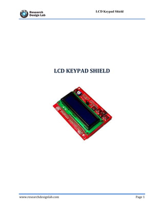
One of the basic interfacing requirements for the hobbyists or electronics enthusiasts is I/P (keypad) and O/P (LCD display) for prototype applications. This shield uses minimum number I/O’s that is 4 bits for LCD data and 2 control signal lines for the same. A single analog pin (Pin A0) is multiplexed to read 5 input key switches (Navigation keys). Each key has been pulled up to a different voltage level, so a different voltage will be generated every time a user selects a key. This voltage could be read by the analog pin A0 on the board. Hence saves the no of I/O pins. The backlight of the LCD could be controlled by setting PWM (Pin D10) by adding a few lines of code.

Recommended
More Related Content
What's hot
Similar to LCD Keypad Shield
Similar to LCD Keypad Shield (20)
More from Raghav Shetty
More from Raghav Shetty (20)
Recently uploaded
Recently uploaded (20)
LCD Keypad Shield
- 1. www.researchdesignlab.com Page 1 LCD Keypad Shield LCD KEYPAD SHIELD
- 2. www.researchdesignlab.com Page 2 LCD Keypad Shield Table of Contents LCD KEYPAD SHIELD ................................................................................................................ 1 OVERVIEW ................................................................................................................................... 3 INTRODUCTION ...................................................................................................................... 3 FEATURES ................................................................................................................................ 3 APPLICATIONS........................................................................................................................ 4 CIRCUIT DIAGRAM ................................................................................................................ 4 ARDUINO CODE ...................................................................................................................... 5 OUTPUT..................................................................................................................................... 8 RELATED PRODUCTS ............................................................................................................ 9
- 3. www.researchdesignlab.com Page 3 LCD Keypad Shield OVERVIEW INTRODUCTION One of the basic interfacing requirements for the hobbyists or electronics enthusiasts is I/P (keypad) and O/P (LCD display) for prototype applications. This shield uses minimum number I/O’s that is 4 bits for LCD data and 2 control signal lines for the same. A single analog pin (Pin A0) is multiplexed to read 5 input key switches (Navigation keys). Each key has been pulled up to a different voltage level, so a different voltage will be generated every time a user selects a key. This voltage could be read by the analog pin A0 on the board. Hence saves the no of I/O pins. The backlight of the LCD could be controlled by setting PWM (Pin D10) by adding a few lines of code. FEATURES 16X2 Blue color back light LCD. A single Analog pin is multiplexed to read 5 input Keys. Optional PWM based Back light control. Stackable on UNO shield High quality PCB FR4 Grade with FPT Certified.
- 4. www.researchdesignlab.com Page 4 LCD Keypad Shield APPLICATIONS Calculators Cameras Cash Registers Clock Radios Digital Meters Hand-held TV & Terminals Hand-held Data Collection Heart Monitoring Devices CIRCUIT DIAGRAM
- 5. www.researchdesignlab.com Page 5 LCD Keypad Shield ARDUINO CODE /* * Project name: LCD KEYPAD Shield * Copyright (c) Researchdesignlab.com * Description: * Test configuration: MCU: ATMEGA328 Dev.Board: Arduino uno Oscillator: 16 MHz Software: Arduino */ /* The circuit: * LCD RS pin to digital pin 12 * LCD Enable pin to digital pin 11 * LCD D4 pin to digital pin 5 * LCD D5 pin to digital pin 4 * LCD D6 pin to digital pin 3 * LCD D7 pin to digital pin 2 * LCD R/W pin to ground * 10K resistor: * ends to +5V and ground * wiper to LCD VO pin (pin 3) */ // include the library code: #include <LiquidCrystal.h> int sensorValue = 0; // value read from the keypad // initialize the library with the numbers of the interface pins LiquidCrystal lcd(12, 11, 5, 4, 3, 2); int sensorPin = A0; void setup() { // set up the LCD's number of columns and rows: lcd.begin(16, 2);
- 6. www.researchdesignlab.com Page 6 LCD Keypad Shield delay(2000); } void loop() { lcd.clear(); // clear lcd display lcd.setCursor(0, 0); // set the cursor to column 0, line 0 lcd.print("LCD KEYPAD Shield"); lcd.setCursor(0, 1); // set the cursor to column 0, line 1 // read the input on analog pin 0 of keypad : sensorValue = analogRead(sensorPin); // check if the keypad is pressed disply keypad on lcd using sensorValue . if(sensorValue<=10) lcd.print("RIGHT KEY"); else if((sensorValue<=492)&&(sensorValue>=482)) lcd.print("DOWN KEY"); else if((sensorValue<=325)&&(sensorValue>=315)) lcd.print("UP KEY"); else if((sensorValue<=595)&&(sensorValue>=585)) lcd.print("LEFT KEY"); else if((sensorValue<=765)&&(sensorValue>=755)) lcd.print("SELECT KEY"); else lcd.print("NO KEY PRESSED"); delay(500); } SERIAL COMMUNICATION const int analogInPin = A0; // Analog input pin that the potentiometer is attached to int sensorValue = 0; // value read from the pot void setup() { // initialize serial communications at 9600 bps: Serial.begin(9600);
- 7. www.researchdesignlab.com Page 7 LCD Keypad Shield delay(1000); } void loop() { // read the analog in value: sensorValue = analogRead(analogInPin); // check if the keypad is pressed disply keypad on lcd using sensorValue . if(sensorValue<=10) { Serial.write(byte(0X01)); Serial.write(byte(0X80)); Serial.println("RIGHT KEY"); }else if((sensorValue<=492)&&(sensorValue>=482)) { Serial.write(byte(0X01)); Serial.write(byte(0X80)); Serial.println("DOWN KEY"); } else if((sensorValue<=325)&&(sensorValue>=315)) { Serial.write(byte(0X01)); Serial.write(byte(0X80)); Serial.println("UP KEY"); } else if((sensorValue<=595)&&(sensorValue>=585)) { Serial.write(byte(0X01)); Serial.write(byte(0X80)); Serial.println("LEFT KEY"); }else if((sensorValue<=765)&&(sensorValue>=755)) { Serial.write(byte(0X01)); Serial.write(byte(0X80)); Serial.println("SELECT KEY"); } else
- 8. www.researchdesignlab.com Page 8 LCD Keypad Shield { Serial.write(byte(0X01)); Serial.write(byte(0X80)); Serial.println("NO KEY PRESSED"); } delay(1000); } OUTPUT
- 9. www.researchdesignlab.com Page 9 LCD Keypad Shield RELATED PRODUCTS RDL- UNO ATMEGA328 Development Board 4x4 Matrix Keypad LCD Interfacing Module Graphical LCD