1. “Robo-Golf”, A Golf Playing Robot
Abstract
This paper presents the design project “Robo-Golf”. Robo-
Golf is a PC based autonomous robot system wherein a
wheeled robot hits a golf ball into a hole in the playing
field, similar to the sport of golf. The system uses visual
feedback from an overhead camera attached to a computer
that is processed a program to determine the positions of
the objects in the field and the appropriate commands to
navigate robot. Wireless communication between the robot
and the computer is done with bluetooth. Robot motion is
achieved using two DC motors that control the two wheels
of the robot. The robot hits the ball with the use of a golf
club controlled by an analog servomotor.
1. Introduction
Robo-Golf is an exciting and challenging robotic domain
aimed at advancing robot intelligence and control. The
main problem of the project is how to make the robot play
golf using vision as the primary source of information.
Figure 1 shows a block diagram of the entire system:
Figure 1: Block diagram of the Robo-Golf system.
2. Vision
Vision is one of the key components of Robo-Golf. Images
are captured by an overhead camera, a commodity webcam
commonly used for video chatting on the internet. The
captured images are processed in a PC or laptop to yield
the coordinates of the robot. The webcam captures images
at a resolution of 640 x 480 pixels.
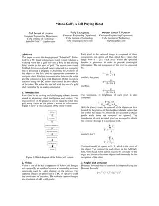
Each pixel in the captured image is composed of three
components, red, green and blue, which have values that
range from 0 – 255. Each pixel within the specified
borders is processed in order to provide meaningful
information. The red component of the pixel is computed
by,
similarly for green,
and blue,
The luminance, or brightness of each pixel is also
computed.
With the above values, the centroid of the objects are then
located by the process of thresholding wherein values that
fall within the range of a threshold are accepted as object
pixels while those not accepted are ignored. The
coordinates of each accepted pixel are averaged to obtain
the centroid. Average X is computed with,
similarly for Y,
The result would be a point at Xc, Yc which is the center of
the object. The centroid for each object in the field(ball,
hole, robot head, robot tail) is required to compute for the
angle and distances between objects and ultimately for the
navigation of the robot.
3. Angles and Distances
Distances between objects/centroids is computed using the
Distance Formula.
Ceff Benzel M. Lozada
Computer Engineering Department,
Cebu Institute of Technology
lmbc0987654321@yahoo.com
Herbert Joseph T. Puracan
Computer Engineering Department,
Cebu Institute of Technology
hjtp02@yahoo.com
Raffy B. Lauglaug
Computer Engineering Department,
Cebu Institute of Technology
raffy_lauglaug@yahoo.com
g=
G
RGB
d=x2−x1
2
y2−y1
2
X c=
∑
i=0
n
X i
i
Y c=
∑
i=0
n
Y i
i
r=
R
RGB
b=
B
RGB
l=
RGB
RmaxGmaxBmax
2. With the distances, angles are computed using the Cosine
Law.
The orientation or bearing of the line between two
centroids is computed using the formula for angle between
two lines
with m being the slope of a line given by the formula for
slope of a line using two points.
The information above makes navigation of the robot
possible.
4. Navigation
The robot is constructed with the golf club perpendicular
to the line between the two wheels.
Figure 2: The Robo-Golf Robot
In order for the robot to shoot the ball, it must be
positioned with the line between its head and tail
perpendicular to the line between the hole and the ball. For
this, a navigation strategy composed of 10 stages was
devised.
Figure 3: A diagram showing the navigation stages.
Navigation works by first getting the x & y location of the
ball, the robot and the hole. After gathering all those
coordinates, the location of the ball and the hole is verified
if they are equal or within 25 pixels tolerance, just to
ensure if the ball is already in the hole. If not, the robot
must now face to where the ball is. This is achieved by
getting the bearing of the robot with respect to its tail and
the bearing of the ball with respect to the tail of the robot.
The angle between the two bearings is then being
computed. If the result is 180 or less the robot will then
turn clockwise in view of the fact that this is the closest
turn to take. But if their angle difference is more than 180
the robot will turn the other way which is counter
clockwise. Provided that the robot is now facing the ball,
the robot will now move forward until it reaches the
allowed minimum distance, 120 pixels in particular. This
minimum distance, we so called, is set in order for the
robot not to move too close to the ball. However this was
applied only at this certain stage, so it is not absolute that
the robot will not bump to the ball in the other stages.
Subsequent to that stage, the bearing of the robot is being
determined if it coincides with the bearing of the ball-to-
hole line. If not, the robot turns either clockwise or counter
clockwise depending on which turn has lesser angle. This
stage uses same approach as that stage where the robot
faces the ball. Once that stage is completed, the robot must
move forward until the angle between the ball-to-hole line
and ball-to-tail line reaches 90 degrees with a certain
tolerance. This is being implemented because the
appropriate angle for the robot to strike the ball is at 90
degrees with regards to ball-to-hole line considering the
fact that the club is situated in the front part of the robot’s
body. Gone past that stage, the robot is again required to
face the ball. The manner of how it will be achieved has
already been discussed above. Then the club must be
swung into its ready position. This is done by comparing
the bearing of the ball with respect to the hole and the
bearing of the tail with respect also to the hole. If the
bearing of the ball is lesser than the bearing of the tail, the
club will be swung to the right side of the robot away from
the hole else the club will be swung to the left side of the
robot away from the hole. In exception to this rule is when
the ball is in the 4th
quadrant and the robot is in the 1st
quadrant where in the actions are being inverted. When
club is ready, the robot will then draw itself closer to the
ball with a lay down minimum distance. Since the robot is,
at the moment, done with all its preparation, the only thing
left to do is to swing the club to the direction of hole trying
to shoot the ball, and then the entire process will be
repeated.
m=
X 2−X 1
Y 2−Y 1
cos A=
b
2
c
2
−a
2
2bc
tan=
m2−m1
1m1
m2
3. 5. Testing and Results
TRIAL ATTEMPTS RESULT
1 1 shot
2 1 shot
3 1 shot
4 5 failed
5 4 shot
6 4 shot
7 1 failed
8 1 failed
9 1 failed
10 1 failed
11 3 shot
12 2 shot
13 1 shot
14 3 failed
15 4 shot
16 3 failed
17 5 failed
Table 1: Ability of the robot to shoot the ball
The test determines the ability of the robot to shoot the
ball. The robot is instructed to follow the navigation
algorithm and autonomously attempts to hit the ball into
the hole. 17 trials were made with the location of the ball
and robot in various quadrants on the playing field. Failure
occurs when: a) the robot exceeds the borders, b) the ball
exceeds the borders, c) the robot becomes unable to move
(e.g. it falls into the hole). d) the robot stops operation
even when the ball is still not in the hole. Based on the
number of successful and failed attempts, the robot has a
52.94% ability to hit the ball into the hole successfully.
The robot can successfully hit the ball into the hole in an
average of 1.24 shots. Most of the errors were random
errors caused by factors like the uneven playing surface.
5. Conclusion
Based from the data gathered and test conducted we can
certainly say that the project was working but not that
perfectly. With the 52.94 percent of success, the group can
say that it somehow exceeded the team’s expectation even
if a lot of improvements are still to be made. The part of
the system that needs to be focused on further
improvements are the image processing part and the
navigation control. The need for a faster response for every
stimulus that the camera captures in the field with respect
to the system’s analysis of the image is of great importance
so that the functionality is at its best.
6. Acknowledgment
Our team would like to extend our heartfelt gratitude to all
the persons who have contributed for the realization of our
project design
7. References
[1] Maravillas, Elmer, Ph.D., Pit, Mark Makinn: Vision
System for Color Object Tracking, 2004
[2] Badea, Florin.:“Bluetooth simulation.” Code Project
Development Source.
June 11, 2008.
http://www.codeproject.com/KB/mobile/bth_seri
al_port.aspx
[3] zer0w1ng:” Bluetooth-Serial Port Controller and Serial
Wireless UART Cable Replacement”
http://www.electronicslab.ph/forum/index.php?
topic=1330.0
[4] Pieter P. Jonker, Jurjen Caarls, Wouter J. Bokhove,
Werner Altewischer, Ian T. Young*
“Autonomous Robots in a Complex
Environment”,2006
[5] Tim Howell, Howard Chang : “RoboSoccer
GamePlay”, Part IV Project Report 2003
[6] Yong Sin Ly,:” Robo-Soccer II ” PART IV Project Final
Report 2003
[7] Nathan Lovell and Vladimir Estivill-Castro, “Color
Classification and Object Recognition for Robot
Soccer Under Variable Illumination”, Griffith
University
Australia
[8] Gordon Wyeth and Ben Brown.” Robust Adaptive
Vision for Robot Soccer”, Computer Science and
Electrical Engineering, University of
Queensland, Brisbane, Australia
[9] http://130.113.54.154/~monger/hsl-rgb.html
[10] http://en.wikipedia.org/wiki/Chromaticity
[11] http://en.wikipedia.org/wiki/Pulse_width_modulation
[12] [http://en.wikipedia.org/wiki/Golf]
[13]
http://en.wikipedia.org/wiki/Segmentation_(image_process
ing)]
[14] [http://en.wikipedia.org/wiki/RGB_color_model]