1. RELAYS:<br />HistoryElectromagnetic relays were once the main ingredient in automated machinery. Factories used to control everything from conveyors to robots with huge panels filled with hundreds of relays clacking away, each in turn. This method had several drawbacks, but for years it was the only method available. <br />Recently, Programmable Logic Controllers (PLCs) have replaced banks of relays for automation needs. Relays are still used in small applications where a PLC would be overkill. They come in several varieties to suit a wide range of applications. <br />Relays have a huge number of uses, but a few very common ones constitute the vast majority. Holding circuits are used to hold power on until the connection is Broken by another signal. This is achieved by connecting one of the relay's own contacts to its coil — once the relay is turned on, it stays on. . Relays are also useful for allowing one signal to switch connections at two or more different voltages since the contacts are isolated from each other. But most often, they are used to switch connections that are at different voltages than the control power.<br />In many cases, control power and signals generated by sensors are generated at low voltages. This is for reasons of safety and efficiency. Low voltage signals, however, are inefficient for doing high-wattage work, so a relay is used to allow the low voltage signal to switch a higher-voltage connection to do work, such as pull in a large solenoid, run a motor. <br />4.7.1 WHAT IS A RELAY?<br />“A relay is an electrical switch that opens and closes under the control of another electrical circuit.” Relays are one of the oldest, simplest, and yet, easiest and most useful devices. Before the advent of the mass produced transistor, computers were made from either relays or vacuum tubes, or both.<br />2806065-525780 <br />The classic electromagnetic relay is a switch which is thrown by an electromagnet. A relatively low current applied to the magnet can throw the switch, allowing a higher current to flow through that switch. The solenoid of most automobiles can be considered an electromagnetic relay. <br />In digital applications, it has been surpassed by the solid state relay. These relays have no moving parts, so they can switch very quickly in response to a control signal. They are built from semiconductors, and they cannot handle the current that an electromagnetic relay could but their advantage is speed. High current solid-state relays often require heat sinks to drain excess heat.<br /> <br />2804160168910 4.7.2 Relay Construction<br />Relays are amazingly simple devices. There are four parts in every relay: <br />Electromagnet <br />Armature that can be attracted by the electromagnet <br />Spring <br />Switching contacts<br />relays construction<br />Relay Contact Information: <br /> Relay contacts on most of our kits and in the industrial world are labeled with<br /> NO (Normally Open), NC (Normally Closed), and CT (Common Terminal). <br />A relay contact is a switch, nothing more, nothing less. It does not provide power; it simply opens and closes an electrical circuit, just like the light switch on a wall. <br />When the relay is de-energized or turned off there is an electrical connection between NC and Common hence normally closed. In the off state there is not a connection between NO and common, hence normally open. <br />When the relay is energized or turned on the NO and C makes an electrical connection and the electrical connection between NC and C is removed.<br /> HYPERLINK quot;
http://www.sea.siemens.com/step/templates/lesson.mason?components:4:3:2quot;
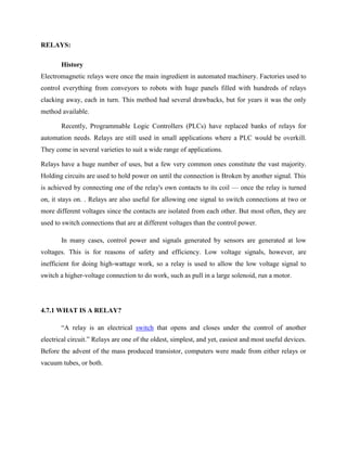
<br /> 4.7.3RELAYS WORKING:<br />271970588900When a current flows through the coil, the resulting magnetic field attracts an armature that is mechanically linked to a moving contact. The movement either makes or breaks a connection with a fixed contact. When the current to the coil is switched off, the armature is returned by a force approximately half as strong as the magnetic force to its relaxed position. Usually this is a spring, but gravity is also used commonly in industrial motor starters. Most relays are manufactured to operate quickly. In a low voltage application, this is to reduce noise. In a high voltage or high current application, this is to reduce arcing.<br />If the coil is energized with DC, a diode is frequently installed across the coil, to dissipate the energy from the collapsing magnetic field at deactivation, which would otherwise generate a spike of voltage and might cause damage to circuit components. If the coil is designed to be energized with AC, a small copper ring can be crimped to the end of the solenoid. This quot;
shading ringquot;
creates a small out-of-phase current, which increases the minimum pull on the armature during the AC cycle. <br /> <br /> Relay operation<br /> <br />4.7.4 CHOOSING OF RELAY:<br />1.Physical size and pin arrangement If you are choosing a relay for an existing PCB you will need to ensure that its dimensions and pin arrangement are suitable. You should find this information in the supplier's catalogue. <br />2.Coil voltage The relay's coil voltage rating and resistance must suit the circuit powering the relay coil. Many relays have a coil rated for a 12V supply but 5V and 24V relays are also readily available. Some relays operate perfectly well with a supply voltage which is a little lower than their rated value. <br />3.Coil resistance The circuit must be able to supply the current required by the relay coil. You can use Ohm's law to calculate the current: <br />Relay coil current = supply voltage coil resistance<br />For example: A 12V supply relay with a coil resistance of 400 passes a current of 30mA. This is OK for a 555 timer IC (maximum output current 200mA), but it is too much for most ICs and they will require a transistor to amplify the current. <br />4.Switch ratings (voltage and current) The relay's switch contacts must be suitable for the circuit they are to control. You will need to check the voltage and current ratings. Note that the voltage rating is usually higher for AC, for example: quot;
5A at 24V DC or 125V ACquot;
. <br />5.Switch contact arrangement (SPDT, DPDT etc) Most relays are SPDT or DPDT which are often described as quot;
single pole changeoverquot;
(SPCO) or quot;
double pole changeoverquot;
(DPCO). For further information please see the page on switches.<br /> 4.7.5Advantages: <br />1.The complete electrical isolation improves safety by ensuring that high voltages and currents cannot appear where they should not be. <br />2.Relays come in all shapes and sizes for different applications and they have various switch contact configurations. Double Pole Double Throw (DPDT) relays are common and even 4-pole types are available. You can therefore control several circuits with one relay or use one relay to control the direction of a motor. <br />3.It is easy to tell when a relay is operating - you can hear a click as the relay switches on and off and you can sometimes see the contacts moving. <br />4.7.6Disadvantages :<br />Being mechanical though, relays do have some disadvantages over other methods of electrical isolation:<br />1.Their parts can wear out as the switch contacts become dirty - high voltages and currents cause sparks between the contacts. <br />2.They cannot be switched on and off at high speeds because they have a slow response and the switch contacts will rapidly wear out due to the sparking. <br />3.Their coils need a fairly high current to energize, which means some micro-electronic circuits can't drive them directly without additional circuitry. <br />4.The back-emf created when the relay coil switches off can damage the components that are driving the coil. To avoid this, a diode can be placed across the relay coil, as will be seen in any Electronics in Meccano circuits that use relays with sensitive components.<br />4.7.7Applications:<br /> Relays are used:<br />1.To control a high-voltage circuit with a low-voltage signal, as in some types of modems. <br />2.To control a high-current circuit with a low-current signal, as in the starter solenoid of an automobile.<br />3.To detect and isolate faults on transmission and distribution lines by opening and closing circuit breakers (protection relays). <br />4.To isolate the controlling circuit from the controlled circuit when the two are at different potentials, for example when controlling a mains-powered device from a low-voltage switch. The latter is often applied to control office lighting as the low voltage wires are easily installed in partitions, which may be often moved as needs change. They may also be controlled by room occupancy detectors in an effort to conserve energy.<br />5.To perform logic functions. For example, the Boolean AND function is realized by connecting NO relay contacts in series, the OR function by connecting NO contacts in parallel. The change-over or Form C contacts perform the XOR (exclusive or) function. Similar functions for NAND and NOR are accomplished using NC contacts. Due to the failure modes of a relay compared with a semiconductor, they are widely used in safety critical logic, such as the control panels of radioactive waste handling machinery. <br />6.To perform time delay functions. Relays can be modified to delay opening or delay closing a set of contacts. A very short (a fraction of a second) delay would use a copper disk between the armature and moving blade assembly. Current flowing in the disk maintains magnetic field for a short time, lengthening release time. For a slightly longer (up to a minute) delay, a dashpot is used. A dashpot is a piston filled with fluid that is allowed to escape slowly. The time period can be varied by increasing or decreasing the flow rate. For longer time periods, a mechanical clockwork timer is installed. <br />