SlideShare a Scribd company logo
1 of 16
Download to read offline
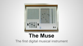
The Muse
The first digital musical instrument
Timeline
1966: 7400 series TTL PDIP
1970: Triadex Incorporated
1970: Patent applied for by inventors Fredkin and Minsky
1971: Popular Electronics February cover article: Psych-Tone
1971: Patent 3,610,801 granted in October
1977: Apple II
1983: MIDI
1997 / 2009: Muse simulator for Windows
2015: Back to the hardware (before the sunset of PDIP)
From the Patent Office
Psych-Tone
Popular Electronics, February 1971
http://www.swtpc.com/mholley/PopularElectronics/Feb1971/PE_Feb1971.htm
“Build the Psych-Tone” by Don Lancaster
complete kit only $47.65 plus postage from SWTPC
What does it do?
“With 14 trillion note combinations, the Muse has four switches for volume,
tempo, pitch, and fine pitch and eight slide switches. Four of the latter vary the
interval and thus determine the notes, while the other four control the theme
and variations of the melody.” - Don Lancaster, 1971
● Stand-alone musical instrument
○ front panel controls
○ loudspeaker output
● Deterministic sequences
● Square wave “voice”
How does it work?
Low Speed Clock (tempo)
Counters
Divide by 6 and divide by 8
31-stage Shift Register
Parity generator (5 bit XOR) for feedback
Eight SP40T switches
Four for sequence feedback W-X-Y-Z and four for pitch A-B-C-D
OFF-ON-C1/2-C1-C2-C4-C8-C3-C6-D1-...-D31
Four bit DCO
High Speed Clock
Load of counter reset value triggered by tempo clock
Count down and reset and repeat (free run)
Algorithm
A timer is used to drive two counters and a 31-stage shift register.
Tempo is set by the timer interval.
Counters and shift register states shown by lights on the panel.
Parity generator: XOR of shift register msb and four samples from W-X-Y-Z.
Parity output is input to shift register lsb.
Interval logic translates a four bit value from A-B-C-D to a note number.
Note number determines period of a square wave.
Simulator: Windows Multimedia API to send MIDI note messages and wave data to available devices.
1997: Software
Same front panel layout, same logic.
Plus Windows File Menu Save, Load.
Plus Settings, Toolbar, MIDI
messages.
2009 Revision by Steven Parker
shown here.
2015: Michael Gianfreda
Recent Prototypes
2015 - part 2
New PIC version.
Programming is done with 1x Parameter-Pot, 1x
Value-Pot, Enter-Key.
Enhanced Muse: 1x 48-bit or 2x 24bit (independent)
shift register, 8x binary counters, 6x ternary counters,
64 parameters instead of 40 of the original.
8 banks EEPROM saves.
Entered Values can be displayed.
Transpose +/- 64 halftones.
Eurorack
● Panel Inputs
○ Interval / Theme input: Eight 60mm slide pots: Bourns PTL60 series
○ Vol / Tempo / Pitch / Fine: Four 20mm slide pots
○ On / Off / Start: SPDT [On-Off-Momentary]
○ Auto / Hold / Step: SPDT [On-Off-Momentary]
○ Rest
● Panel Display
○ 40 LEDs for counters and shift register
○ New: 3 character alphanumeric display for slider position feedback
● Microcontroller core
○ A to D for Interval / Theme inputs
○ LED drive via multiplex
● Voltage Control
○ Tempo, Pitch, Start, Reset
● Voltage Outputs
○ Pitch encoded as voltage
○ Audio
○ Tempo Clock
Block Diagram
Panel:
sliders / LEDs /
switches
CPU
12x analog lines
4x digital lines:
run/stop,
reset,
step (pulse),
rest
40x digital lines
pitch and
clock out
Multiplexers,
LED drivers
6 + 1 bits: LED position, data;
3 bytes: position feedback
.
.
.
.
.
.
..
.
.
.
position feedback
Position Feedback
● CPU checks all 60mm slider positions about 10 times per second
● CPU detects change in position and
○ Changes internal state of slider position in code
○ Updates feedback display with slider name and position
○ Sliders are named A - B - C - D - W - X - Y - Z
○ Positions are numbered 0 to 39 (or 1 - 40)
● No position feedback for 20mm sliders
Programming
● Scan sliders and quantize
○ 10 ms scan rate
○ update internal registers
● Drive slider feedback display
○ send last slider update to display
● Counters
○ divide by 3 / 6
○ divide by 2 / 4 / 8
● Shift Register
○ long integer
● Parity Generator
○ exclusive OR
● Pitch computation
○ (1 x A + 2 x B + 4 x C + 8 x D)
○ is this a rest?
○ look up note value for scale in use
○ add coarse and fine pitch offsets and convert to voltage
● Clock output
Digital or Analog?
Options for the 40-position switches
1. use a slide potentiometer and convert voltage to a number. Use the number to decide what position to sample in
the counters or shift register.
a. Easier to do in software.
b. Detents are hard to do.
2. or 3D print a real switch. Bring the shift register and counter states out to digital lines.
a. Detents are part of the print.
b. Where does the shift register live? Hardware or software?
Tuning
● The Muse used a high speed clock with analog rate controls.
● Tuning in software means more analog to digital conversion.
Business Plan
● Market Research
○ Potential sales of 100 units in one year
○ Target Price around $400 (like the original!)
● Cost to design
○ Complete schematic
○ Protoype
○ Panel layout
● Cost to build
○ Panel
○ PCB
○ Components
■ 60mm slide pots are $2.36 at Mouser
○ Construction
○ Packaging
○ Cost of Sales

More Related Content

What's hot

Encoders and decoders
Encoders and decodersEncoders and decoders
Encoders and decodersGaditek
 
Types of encoders and decoders with truth tables
Types of encoders and decoders with truth tablesTypes of encoders and decoders with truth tables
Types of encoders and decoders with truth tablesAbdullah khawar
 
 multiplexer 
 multiplexer  multiplexer 
 multiplexer rounak077
 
Digital Counter Design
 Digital Counter Design Digital Counter Design
Digital Counter DesignGargiKhanna1
 
LinnStrument : the ultimate open-source hacker instrument
LinnStrument : the ultimate open-source hacker instrumentLinnStrument : the ultimate open-source hacker instrument
LinnStrument : the ultimate open-source hacker instrumentGeert Bevin
 

What's hot (7)

Encoders and decoders
Encoders and decodersEncoders and decoders
Encoders and decoders
 
Types of encoders and decoders with truth tables
Types of encoders and decoders with truth tablesTypes of encoders and decoders with truth tables
Types of encoders and decoders with truth tables
 
Lec10
Lec10Lec10
Lec10
 
 multiplexer 
 multiplexer  multiplexer 
 multiplexer 
 
Prestentation
PrestentationPrestentation
Prestentation
 
Digital Counter Design
 Digital Counter Design Digital Counter Design
Digital Counter Design
 
LinnStrument : the ultimate open-source hacker instrument
LinnStrument : the ultimate open-source hacker instrumentLinnStrument : the ultimate open-source hacker instrument
LinnStrument : the ultimate open-source hacker instrument
 

Similar to Triadex Muse

Similar to Triadex Muse (20)

8086 architecture-unit-1
8086 architecture-unit-18086 architecture-unit-1
8086 architecture-unit-1
 
Microprocessor history1
Microprocessor history1Microprocessor history1
Microprocessor history1
 
Microprocessor history1
Microprocessor history1Microprocessor history1
Microprocessor history1
 
Introduction to Microprocessor lecture 01
Introduction to Microprocessor lecture  01Introduction to Microprocessor lecture  01
Introduction to Microprocessor lecture 01
 
Unit 1
Unit 1Unit 1
Unit 1
 
Generation of Computer Network
Generation of Computer NetworkGeneration of Computer Network
Generation of Computer Network
 
How to use a Function generator
How to use a Function generatorHow to use a Function generator
How to use a Function generator
 
WhatIsComputer.ppt
WhatIsComputer.pptWhatIsComputer.ppt
WhatIsComputer.ppt
 
Chapter#4
Chapter#4Chapter#4
Chapter#4
 
Chapter 1.pptx
Chapter 1.pptxChapter 1.pptx
Chapter 1.pptx
 
Microcontroller 8051
Microcontroller 8051Microcontroller 8051
Microcontroller 8051
 
The MIDI Protocol - Musical Instrument Digital Interface
The MIDI Protocol - Musical Instrument Digital InterfaceThe MIDI Protocol - Musical Instrument Digital Interface
The MIDI Protocol - Musical Instrument Digital Interface
 
Punch sensor, Arduino
Punch sensor, Arduino Punch sensor, Arduino
Punch sensor, Arduino
 
Lecture 3 - Driving.pdf
Lecture 3 - Driving.pdfLecture 3 - Driving.pdf
Lecture 3 - Driving.pdf
 
Mixer v1.0.3
Mixer v1.0.3Mixer v1.0.3
Mixer v1.0.3
 
Microcontroller 8051
Microcontroller 8051Microcontroller 8051
Microcontroller 8051
 
01 v96i qg_en_b0
01 v96i qg_en_b001 v96i qg_en_b0
01 v96i qg_en_b0
 
Microprocessor Introduction
Microprocessor IntroductionMicroprocessor Introduction
Microprocessor Introduction
 
1 PageAlarm Clock Design Using PIC18F45E.docx
1  PageAlarm Clock Design Using PIC18F45E.docx1  PageAlarm Clock Design Using PIC18F45E.docx
1 PageAlarm Clock Design Using PIC18F45E.docx
 
EE6502 Microprocessor & Microcontroller Regulation 2013
EE6502 Microprocessor & Microcontroller Regulation 2013EE6502 Microprocessor & Microcontroller Regulation 2013
EE6502 Microprocessor & Microcontroller Regulation 2013
 

Triadex Muse

  • 1. The Muse The first digital musical instrument
  • 2. Timeline 1966: 7400 series TTL PDIP 1970: Triadex Incorporated 1970: Patent applied for by inventors Fredkin and Minsky 1971: Popular Electronics February cover article: Psych-Tone 1971: Patent 3,610,801 granted in October 1977: Apple II 1983: MIDI 1997 / 2009: Muse simulator for Windows 2015: Back to the hardware (before the sunset of PDIP)
  • 4. Psych-Tone Popular Electronics, February 1971 http://www.swtpc.com/mholley/PopularElectronics/Feb1971/PE_Feb1971.htm “Build the Psych-Tone” by Don Lancaster complete kit only $47.65 plus postage from SWTPC
  • 5. What does it do? “With 14 trillion note combinations, the Muse has four switches for volume, tempo, pitch, and fine pitch and eight slide switches. Four of the latter vary the interval and thus determine the notes, while the other four control the theme and variations of the melody.” - Don Lancaster, 1971 ● Stand-alone musical instrument ○ front panel controls ○ loudspeaker output ● Deterministic sequences ● Square wave “voice”
  • 6. How does it work? Low Speed Clock (tempo) Counters Divide by 6 and divide by 8 31-stage Shift Register Parity generator (5 bit XOR) for feedback Eight SP40T switches Four for sequence feedback W-X-Y-Z and four for pitch A-B-C-D OFF-ON-C1/2-C1-C2-C4-C8-C3-C6-D1-...-D31 Four bit DCO High Speed Clock Load of counter reset value triggered by tempo clock Count down and reset and repeat (free run)
  • 7. Algorithm A timer is used to drive two counters and a 31-stage shift register. Tempo is set by the timer interval. Counters and shift register states shown by lights on the panel. Parity generator: XOR of shift register msb and four samples from W-X-Y-Z. Parity output is input to shift register lsb. Interval logic translates a four bit value from A-B-C-D to a note number. Note number determines period of a square wave. Simulator: Windows Multimedia API to send MIDI note messages and wave data to available devices.
  • 8. 1997: Software Same front panel layout, same logic. Plus Windows File Menu Save, Load. Plus Settings, Toolbar, MIDI messages. 2009 Revision by Steven Parker shown here.
  • 10. 2015 - part 2 New PIC version. Programming is done with 1x Parameter-Pot, 1x Value-Pot, Enter-Key. Enhanced Muse: 1x 48-bit or 2x 24bit (independent) shift register, 8x binary counters, 6x ternary counters, 64 parameters instead of 40 of the original. 8 banks EEPROM saves. Entered Values can be displayed. Transpose +/- 64 halftones.
  • 11. Eurorack ● Panel Inputs ○ Interval / Theme input: Eight 60mm slide pots: Bourns PTL60 series ○ Vol / Tempo / Pitch / Fine: Four 20mm slide pots ○ On / Off / Start: SPDT [On-Off-Momentary] ○ Auto / Hold / Step: SPDT [On-Off-Momentary] ○ Rest ● Panel Display ○ 40 LEDs for counters and shift register ○ New: 3 character alphanumeric display for slider position feedback ● Microcontroller core ○ A to D for Interval / Theme inputs ○ LED drive via multiplex ● Voltage Control ○ Tempo, Pitch, Start, Reset ● Voltage Outputs ○ Pitch encoded as voltage ○ Audio ○ Tempo Clock
  • 12. Block Diagram Panel: sliders / LEDs / switches CPU 12x analog lines 4x digital lines: run/stop, reset, step (pulse), rest 40x digital lines pitch and clock out Multiplexers, LED drivers 6 + 1 bits: LED position, data; 3 bytes: position feedback . . . . . . .. . . . position feedback
  • 13. Position Feedback ● CPU checks all 60mm slider positions about 10 times per second ● CPU detects change in position and ○ Changes internal state of slider position in code ○ Updates feedback display with slider name and position ○ Sliders are named A - B - C - D - W - X - Y - Z ○ Positions are numbered 0 to 39 (or 1 - 40) ● No position feedback for 20mm sliders
  • 14. Programming ● Scan sliders and quantize ○ 10 ms scan rate ○ update internal registers ● Drive slider feedback display ○ send last slider update to display ● Counters ○ divide by 3 / 6 ○ divide by 2 / 4 / 8 ● Shift Register ○ long integer ● Parity Generator ○ exclusive OR ● Pitch computation ○ (1 x A + 2 x B + 4 x C + 8 x D) ○ is this a rest? ○ look up note value for scale in use ○ add coarse and fine pitch offsets and convert to voltage ● Clock output
  • 15. Digital or Analog? Options for the 40-position switches 1. use a slide potentiometer and convert voltage to a number. Use the number to decide what position to sample in the counters or shift register. a. Easier to do in software. b. Detents are hard to do. 2. or 3D print a real switch. Bring the shift register and counter states out to digital lines. a. Detents are part of the print. b. Where does the shift register live? Hardware or software? Tuning ● The Muse used a high speed clock with analog rate controls. ● Tuning in software means more analog to digital conversion.
  • 16. Business Plan ● Market Research ○ Potential sales of 100 units in one year ○ Target Price around $400 (like the original!) ● Cost to design ○ Complete schematic ○ Protoype ○ Panel layout ● Cost to build ○ Panel ○ PCB ○ Components ■ 60mm slide pots are $2.36 at Mouser ○ Construction ○ Packaging ○ Cost of Sales