This document provides an overview of ball grid array (BGA) package design for manufacturability. It discusses BGA package types, ball types, and considerations for designing the BGA land pattern on a printed circuit board. Key points include choosing ball types based on the coefficient of thermal expansion difference between the package and board substrates, and designing the land pattern layout and ball pads to balance reliability, cost and manufacturability factors. Guidelines are provided for pad sizes, trace widths and via sizes based on the ball pitch and package size.
young call girls in Pandav nagar 🔝 9953056974 🔝 Delhi escort Service
Bga land pattern design for manufacturability
1. 1 of 7
BGA Land Pattern Design For Manufacturability
Paul W. Ave
Introduction
This paper outlines and compares the basic characteristics of
Ball Grid Array or “BGA” packages, and lists in guideline
form how to design for manufacturability a specific BGA
land pattern on a given part package.
BGA Overview
Basically there are two main categories that BGA packages
fit into. First the package either has a “Collapsible ball” or
it has a “Non-Collapsible ball”. Typically which type of
ball chosen for a given package is usually dependent upon
the magnitude of difference between the Coefficient of
Thermal Expansion, or CTE, of the BGA package’s
substrate and the “motherboard’s” substrate. These type of
devices are most commonly mounted on tetrafunctional
Flame Retardant epoxy based laminates such as FR-4 and
are usually designed as such. For relatively small CTE
deltas, the component mounting balls are comprised of the
eutectic alloy 63%Sn/37%Pb with a melting point of 183 C
or a the near eutectic alloy 62%Sn/36%Pb/2%Ag with a
melting range of 179-189 C. This is the reason for the label
of “Collapsible Ball” because these type of alloys will melt
in the range of a typical FR-4 assembly’s Infra-Red or “IR”
reflow temperatures. For relatively high CTE deltas the
component mounting balls are comprised of the alloy
10%Sn/90%Pb with a melting range of 268-302C. This
type of alloy is outside the normal IR reflow temperature
ranges and does not melt or is “Non-Collapsible”. Please
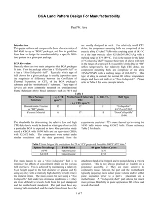
refer to Table 1 for some example details.
Table 1
BGA Package
Substrate
~ x,y CTE
ppm/C
Motherboard Substrate
FR4
~ x,y CTE ppm/C
DELTA Ball Type
Bismaleimide-Triazine
or “BT” plastic
15 17 2 “Collapsible”
63/37 or 62/36/2
Ceramic Material 6 17 11 “Non-Collapsible”
10/90
The thresholds for determining the relative low and high
CTE delta levels would be based on what type of service life
a particular BGA is expected to have. One particular study
tested a CBGA with 10/90 balls and an equivalent CBGA
with 62/36/2 balls. The components were tested under
similar conditions and the data generated from the
experiments predicted 175% more thermal cycles using the
10/90 balls versus using 63/36/2 balls. Please reference
Table 2 for details.
Table 2 Joint fatigue life predictions for 25 to 55C projected from 0 to 100C ATC data.1
Sphere Metallurgy PWB Finish 100 ppm Failure Cycles
10/90 benzotriazole 7550
62/36/2 benzotriazole 2750
The main reason to use a “Non-Collapsible” ball is to
minimize the effects of concentrated strain on the various
ball interfaces. This is achieved by maintaining a relatively
fixed height equal to the ball diameter or greater and by
using an alloy with a relatively high ductility to help relieve
the induced strain. The main reason for not using a “Non
Collapsible” ball under less strenuous conditions is 1) they
are more difficult to rework, both from the part standpoint
and the motherboard standpoint. The part must have any
missing balls reattached, and the motherboard must have the
attachment land area prepped and re-pasted during a rework
operation. This is not always practical or feasible on a
populated assembly. 2) They are more sensitive to
coplanarity issues between the part and the motherboard
typically requiring more solder paste volume and/or solder
paste inspection prior to a part’s placement on a
motherboard. A “Collapsible-Ball” part allows for much
more process flexibility in paste application, IR reflow and
rework if needed.
2. 2 of 7
The choice of what type of substrate is used on a part is
primarily the part manufacturer’s choice based on how much
heat the part’s die will need dissipated, and other factors
such as the allowable levels of parasitic inductance and
capacitance. Typically ceramic or similar type materials
have been the choice for devices over 5 watts in power and
have been shown to have better inductance characteristics
due to shorter internal bond wires.
The greatest point of shear strain and the most likely point
of first time solder joint failure for a particular part package
is again related to the CTE mismatch of the part and the
motherboard’s substrate. Basically for ceramic type parts
mounted on FR-4, the greater the distance you are from the
“Neutral Point” (DNP) which in these cases is from the
center of the part package outward, the higher the shear
strain on the solder joint. So in other words, the peripheral
areas or the outside solder joints should show the first
fatigue failures. BT plastic parts will show failures on a
relatively small DNP or somewhere on the inside of the ball
array nearest the part’s silicon die. Refer to Figure 1.
Figure 1
FIRST FAILURES OCCUR AT
THE JOINTS FARTHEST FROM
THE NEUTRAL POINT
FIRST FAILURES OCCUR AT
THE JOINTS CLOSEST TO
THE NEUTRAL POINT
BT PLASTIC CERAMIC
NP NP
The second main category of description for BGAs has to do
with how the balls on the part are oriented. They can be
configured either as “Full Grid” or “Perimeter” parts with
ball spacings or pitches typically at 1.5 mm, 1.27 mm, and
1.0 mm. The Full Grid parts are usually the higher pitch
parts starting at 1.5mm and below. The Perimeter parts
usually have the smaller ball pitches at 1.27 and below
which allows them to achieve a greater number of balls per
square inch, and are easier to route during pc-board layout
than a comparable Full Grid Part. The increase in
routability is because of the open area available toward the
center of the part. Please refer to Figure 2 for examples of
some common part ball layout configurations available.
Figure 2
N
P
R
G
K
M
L
J
H
F
E
D
C
B
1 2 3 4 5 6 7 8 9 10 11 12 13 14 15
A
.060in(1.5mm) .050in(1.27mm)
FULL GRID
225 BGA
PERIMETER
256 BGA
3. 3 of 7
DFM Layout Concerns for BGAs
There are two main areas to consider when laying out and
creating a BGA land pattern for a PC board assembly. First,
you want to consider how you are going to route or fan out
the land pattern for the part. This decision involves a
compromise between the desired cost of the board and the
limiting physical characteristics of the part. The ideal
situation would be to create a layout that involved a PC
board with a minimal layer count and included the most cost
effective trace widths and via sizes while continuing to
provide a highly reliable and easily manufactured assembly.
Which, is sometimes easier said than done with the higher
ball count lower pitch devices.
Listed in Table 3 are some relative cost comparisons
between different board lay-up scenarios. Table 3
compares boards that are the same size and have the same
number of holes. It is clearly evident, that layer count has
the most significant impact overall on the PCB cost followed
by trace width and hole size as the next contributing factors.
An eight layer PCB for example can cost over twice as much
as a comparable four layer PCB.
Table 3
Relative PCB Cost Comparisons
4 LAYER 6 LAYER 8 LAYER
Minimum Hole/Pad 18/36 18/30 13.5/24 18/36 18/30 13.5/24 18/36 18/30 13.5/24
8/8 100% 102% 106% 158% 160% 163% 204% 206% 210%
Minimum 6/6 101% 103% 107% 159% 161% 163% 205% 207% 211%
Lines/Spacing 5/5 108% 109% 113% 164% 166% 169% 213% 215% 219%
You mainly have three types of balls to route on any BGA
part. They are power, ground, and signal or I/O pins. The
board complexity will grow as the number of pins or balls
increase, and as the pitch between the balls decreases. A
cost effective design would focus on routing the signal balls
on the outer layers of the PCB and connecting the power and
ground connections down to inner layer power and ground
planes.
The second main area of layout concern is related to
manufacturing and rework. The BGA’s position on a given
assembly can be crucial in assembly and rework operations.
The component must be located in an accessible area, and in
a position where manufacturing defects are kept at a
minimum. Also, proper part clearances must be maintained
to allow for any rework nozzles to come near or in contact
with the component for any needed part removal.
The Ball Mounting Pad
There are basically two categories of pad design for the part
balls to mount onto. One being a pad that is called a
“Solder-Mask Defined” or SMD pad. The other being
called a “Non-Solder-Mask Defined” or NSMD pad. Please
refer to Figure 3 for pictorial example.
The NSMD pad has a number of advantages over the use of
a SMD pad. The two most notably being 1) for an
equivalent ball mounting area a NSMD pad will take up less
board real-estate than a SMD pad. Figure 3 shows that a
SMD pad requires approximately .010”(.254mm) more
diameter or 4.24 X 10⁻⁴
in2
of copper area. The extra area
saved using a NSMD pad can prove to be invaluable for the
routing of signal traces. 2) The NSMD defined pad has
been shown in several studies using PBGAs and CBGAs to
provide a more reliable solder joint connection than an
equivalent SMD pad. The reason for this improvement is
thought to be the solder stress concentration reduction
associated with NSMD pads. The singularity point where
the solder attaches to the pad at an approximately right angle
on an SMD pad is replaced by an acute stress concentration
point for the NSMD pads2
. One particular study done using
different vendor PBGAs showed SMD pad solder joint
failures at 900 thermal cycles earlier than the equivalent
NSMD pads. However, the rate at which the SMD samples
failed was less than that of the devices using NSMD pads3
.
One advantage that a SMD pad does have over a NSMD pad
however is that a SMD pad provides better hold down for a
pad and therefore provides less of a risk of the pad lifting
during a rework operation.
Figure 3
°X DIA.°X+.010"(.254mm)DIA.
SMD PAD NSMD PAD
4. 4 of 7
Designing the BGA Footprint
For each given category of pad there are essentially three
types of configurations. First is a single pad without a trace
not necessarily connected to anything that provides a
mechanical connection. Second is a single pad with a signal
trace connection, and third is a single pad with a via
attachment to allow a connection to a remote layer. Please
refer to Figure 4 for some pictorial examples of the pads.
Figure 4
Different Types of Ball Mounting Pads
SINGLE PAD
WITHOUT TRACE
SINGLE PAD WITH
VIA CONNECTION
SINGLE PAD
WITH TRACE
The number of traces that can be routed between two given
pads is a function of the part ball pitch and the chosen
finished pad and via sizes. Originally when BGAs were first
introduced, part vendor’s recommended nominal pad sizes at
or near the ball size of the part. Since then additional
studies have been conducted to determine the long term
reliability of different pad configurations with reduced sizes.
Having the flexibility to use smaller pad sizes allows a
designer to use the most economical technology to achieve
the parts layout. One particular study performed on PBGAs
with nominal ball diameters of 0.030”(0.762mm), found that
NSMD pad diameters as small as 0.014”(0.356mm) could
be used without a degradation in the solder joint reliability.
Due to the increased stand-off height achieved with the
smaller pads, it is believed the smaller pads may show
improved reliability over the larger control pad samples
used which were 0.024”(0.610mm) in diameter.4
The main
concerns to be aware of are that a finished pad will have a
tolerance of approximately 0.0015”(0.0381mm). Which
means that if you specify the artwork to have a
0.020”(0.508mm) pad diameter, you could see a range of
0.0185”(0.470mm) - 0.0215(0.546mm) for finished pad
sizes on the PCB. Another concern is the reduced amount of
adhesion you will have by decreasing the available surface
area of the pad, which can lead to an increased number of
lifted pads during any needed rework operations. The same
study that looked at reduced pad diameters also took this
into consideration, and tested the various pad sizes under
rework operations. A rework process was developed to
accommodate NSMD 0.018”(0.457mm) - 0.024”(0.610mm)
pads. Although a low level of pad lift on the
0.014”(.356mm) and 0.016”(0.406mm) pads was observed,
the reliability of all other reworked joints (0.014”(.356mm) -
0.024”(0.610mm) surpassed 1000 cycles of solder joint
reliability testing.4
The conditions of the solder joint
reliability test were -25C/100C with 15 minute dwells at
each extreme. Any resistance reading increase of 100%
from the initial continuity reading was considered a failure.
Once a study completes 1000 thermal shock cycles with no
failures, the solder joint reliability is considered acceptable
for low power PC applications (ASICs, chipsets, memory).4
The examples that follow in this paper will focus around the
application of a 0.020”(0.508mm) pad for use with a part
having a nominal ball diameter of .030”(0.762mm) spaced at
a pitch of .050”(1.27mm). Also it should be noted that the
data referenced in this paper was applied to specific
situations. Although theoretically the same designs could be
applied to similar conditions, it is recommended that
anyone’s particular application be tested or qualified in the
intended design and process environment. This always
makes good engineering sense.
Typically the outside rows and columns of a given part
contain the majority of the signal balls. Table 4 contains
some examples of different options. Listed in bold type in
each of the row scenario columns of the table are the total
number of balls for a Perimeter package or it can be used to
represent the number of signal balls on a Full Grid package.
The RXC dimension specifies the number of balls per row
and column for a given part array.
Table 4
Examples of Different BGA Configurations
Body .050” (1.27 mm) Pitch
Size/Side 4 Row 5 Row 6 Row
1.075”
(27 mm)
256
20X20
300
20X20
336
20X20
1.220”
(31mm)
304
23X23
360
23X23
408
23X23
1.378”
(35mm)
352
26X26
420
26X26
480
26X26
1.476”
(37.5mm)
384
28X28
460
28X28
528
28X28
1.575”
(40mm)
416
30X30
500
30X30
576
30X30
1.673”
(42.5mm)
448
32X32
540
32X32
624
32X32
The body sizes listed are square and can reach sizes in
excess of 1.673”X1.673”(42.5 mmX42.5mm). A user
should use caution when selecting a larger size package to
be aware that a given pick and place machine used in the
assembly process has certain size and weight limitations
which these type packages may approach.
Table 5 lists some recommendations for the most
economical scenarios of via/annular ring sizes, and
lines/spacing widths that can be used with .020”(.508mm)
pads on .050”(1.27mm) pitch spacings.
5. 5 of 7
Table 5
Specification Recommendations for
.050”(1.27mm) Spaced .020”(.508mm) Diameter Pads
Number of Signal Rows 4 5 6
Via Annular Ring/Drill
Diameters (Dr/Dv mils)
36/18 30/18 24/13.5
Lines/Spacings
Widths (Wl/Ws mils)
6/6 6/6 5/5
Max Number of Traces
Between Top Pads
1 2 2
Max Number of Traces
Between Bottom Pads
1 1 2
Figure 5 shows three examples of what the top layers of land
pattern footprints would look like for a Full Grid BGAs with
four, five, and six signal rows with .050”(1.27mm) pitch
spacings. Figure 6 shows what the bottom layers and their
various configurations would look like for the same type
parts. All of the BGA pads with vias have their holes
interstitially positioned and are located between the centers
of the surrounding pads. Please refer to Figure 7 for details
on the exact dimensions.
Figure 7
Exact Dimensions Diagram
.025"(.635mm)
.025"(.635mm)
.050"(1.27mm)
.050"(1.27mm)
Dr Dv
.020(.508mm)
Ws
Wl
.050"(1.27mm)
The via annular ring is designed to neck down and meet the
mounting pad at the outside of the pad’s solder-mask
clearance. The width of the narrowest section of the neck
can be in the range of approximately 25%-75% of the
mounting pad diameter . This neck down section is the most
likely point that a fatigue crack will begin to propagate since
it is in essence a solder-mask defined area which will have
the same undesirable stress concentrations associated with
NSMD pads. However, the widest design will provide
some added resistance to pad lifting. Also on the bottom
side it is recommended that the via annular ring connection
to a trace have a fillet or neck down section. This will
reduce the possibility of drill breakout which can cause
discontinuity between a via and a trace. Via hole pads that
are not used on the bottom layer will be used to connect to
internal layer power and ground planes.
Figure 5
Top Layer Full Grid BGA Land Pattern for a .050”(1.27mm) Pitch Part
4 Signal Rows 5 Signal Rows 6 Signal Rows
Figure 6
Bottom Layer Full Grid BGA Land Pattern for a .050”(1.27mm) Pitch Part
4 Signal Rows 5 Signal Rows 6 Signal Rows
Solder-Mask Clearances
The recommended nominal solder-mask clearance for a
given NSMD pad is .006”(.152mm) greater than the pad or
for these examples .026”(.660mm). The recommended
solder-mask clearance for the via on both sides of a PCB is
equal to the particular via’s annular ring diameter. A wider
6. 6 of 7
clearance equal to that used on the mounting pad could be
used, but the risk of exposing the copper on closely spaced
traces will be greater. Remember, that every feature has
registration and artwork tolerances. Please refer to Figure 8
for more details on mask clearances.
Figure 8
Solder Mask Clearances on Various Features
MASK CLEARANCE = VIA ANNULAR RING DIA.
MASK CLEARANCE = PAD SIZE + .006"(.152mm)
Strategic Component Placement
Where you place a component can actually affect an
assembly’s manufacturability and the number of defects
created for that assembly. The larger board assemblies
approximately 8”(203.2mm) wide and greater can be more
prone to warpage while suspended between two conveyor
belts. Assuming a relatively even top side mass distribution,
the board will naturally follow the shape of a catenary or
parabolic arch as it begins to approach its glass transition
temperature. This shape would show a more pronounced
warp towards its center. FR-4 begins to soften around 135C
which is before the melting point of the 63/37 solderpaste.
So, it is a good practice on the wider boards approximately
8”(203.2mm) or greater to position a part toward the outside
edges of the PCB. Figure 9 shows an exaggerated example
of the potential problem. The problem would be more
severe for the larger size BGAs, and for those parts that are
made of more rigid materials with Non-Collapsible balls.
The components should be positioned on the outside to fit
within your normal DFM guidelines of machine and
conveyor clearances.
Figure 9
Board Warpage Comparison
The PCB Outside Edges vs. The PCB Center
An Exaggerated View
Another advantage to positioning the component towards the
outside of the PCB is that it will allow for easier
accessibility should any troubleshooting or rework be
required.
Rework Clearances
The part’s footprint should also be laid out taking into
consideration the clearances necessary to allow for any
needed rework machine to come in close contact with the
intended part. The first consideration would be for the top
side of the PCB. A good default value would be a
.100”(2.54mm) component keepout zone around the
maximum outside dimension of the part. One aide that a
designer can use would be to incorporate an outline box
equal to the maximum outside dimension of a part plus the
nozzle clearance onto the silkscreen layer of the part’s
footprint. It would also be a good practice to add the row
and column alphanumeric numeric ball identifiers to help
anyone in troubleshooting, and for identifying correct part
polarity on the PCB. Figure 10 shows a pictorial example of
this. Please note that the circular pads shown in Figure 10
are there merely for reference, and normally would not be
part of the final silkscreen image.
Figure 10
BGA Silkscreen Layer with
Some Recommended Part Clearances
N
P
R
G
K
M
L
J
H
F
E
D
C
B
1 2 3 4 5 6 7 8 9 10 11 12 13 14 15
A
X
X
SILKSCREEN OUTLINE
X=MAX. PART WIDTH + NOZZLE CLEARANCE
0.100"(2.54mm) 0.100"(2.54mm)
0.625"(15.875mm) MAX ALLOWABLE PART HEIGHT UNDER PART
The bottom side of the PCB assembly will also have
maximum component height restrictions when bottom side
heat diffusers are used to heat a part from the underside of
an assembly. Though not always necessary on PBGAs it is
almost imperative to use a bottom side diffuser with
CBGAs.
Summary
BGAs have been adopted as a viable replacement to high
I/O fine pitch QFPs. The components themselves however,
can sometimes prove to be a challenge as far as being a cost
effective alternative. To overcome this, designers must
understand the basic characteristics of an intended part, and
be aware that through proper considerations they can
develop a cost effective yet highly reliable assembly. The
basis for this is rooted in proper footprint design for
manufacturability.
Acknowledgments
Special acknowledgments go to Jason Brown of Peak
Plastics , Andrew Mawer of Motorola, Cindy Ramirez, and
Pat Hession of Compaq Computer for data, information ,
and support provided for this paper.
References
1. D.R. Banks, T.E. Burnette, R.D. Gerke, E. Mammo,
and S. Mattay. “Reliability Comparison of Two
Metallurgies for Ceramic Ball Grid Array” ,
Proceedings of the 1994, International Conference on
Multichip Modules, Denver, CO pp. 529-534.
2. A. Mawer, D. Cho, and R. Darveaux. “The Effect of
PBGA Solder Pad Geometry On Solder Joint
7. 7 of 7
Reliability”, Proceedings of the 1996, Surface Mount
International, San Jose, CA, p.135.
3. C. Ramirez, and S. Fauser. “Fatigue Life Comparison
of The Perimeter and Full Plastic Ball Grid Array”,
Proceedings of the 1994, Surface Mount International,
San Jose, CA, p. 259.
4. J.D. Brown, and B. Bromley. “PBGA Solder Joint
Reliability/Manufacturability as a Function of PCB Pad
Size”, Proceedings of the 1996, Surface Mount
International, San Jose, CA, pp. 162-165.