

Recommended
More Related Content
What's hot
What's hot (20)
Viewers also liked
Similar to Assignmentl3 solutions
Similar to Assignmentl3 solutions (20)
Recently uploaded
Recently uploaded (20)
Assignmentl3 solutions
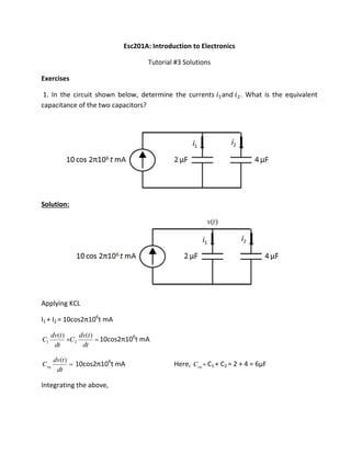
- 1. Esc201A: Introduction to Electronics Tutorial #3 Solutions Exercises 1. In the circuit shown below, determine the currents and . What is the equivalent capacitance of the two capacitors? Solution: Applying KCL I1 + I2 = os π 6 t mA dt tdv C dt tdv C )()( 21 os π 6 t mA dt tdv Ceq )( os π 6 t mA Here, eqC = C1 + C2 = 2 + 4 = 6µF Integrating the above,
- 2. )(tv = eq 6 C102 10 sin π 6 t volts, I1(t) = 3 1 os π 6 t mA, and I2(t) = 3 2 os π 6 t mA 2. For the circuit given below the switch moves from position A to B at = . Assuming that the switch was in position A for a long time before moving to B, determine the apa ito oltage as a fu tio of ti e. ‘epeat if esisto is kΩ a d apa ito is pF. Plot the capacitor voltage versus time for both cases on the same plot. Solution: At t< 0, switch is at A so the capacitance gets charged up to 4 V. So Vini = 4 V. Afte o i g s it h to B, at t = ∞, oltage a oss apa ita e ill e Vf = 0 V (Fully discharged). Now for t > 0, Vc(t) = Vf + (Vini – Vf)exp(-t/τ = 0 + (4 - 0)exp(-t/ τ1) = 4 exp(-t/τ1 olts, he e τ1= R1C1 = 8 ns Similarly, Vc(t) = 4exp(-t/τ2 olts, he e τ2= R2C2 = 12 ns. Both voltages are plotted in the figure above.
- 3. 3. The circuit shown below consists of virtually parallel capacitors being driven by a voltage source of 5 V that is connected to the capacitors at = . Determine the voltage �� and plot the same. Solution: At t=0- , At t = ∞ ∴ �� − = � Under steady state DC conditions, capacitor behaves as an open circuit. Here, both the capacitors have been connected since t = -∞ �� ∞ = � This is a steady state condition for capacitors as well. So they behave as open circuits.
- 4. Since, �� = �� ∞ + �� − �� ∞ exp − /� �� = − exp − �⁄ Vi tuall pa allel apa ito s e ui ale t apa ita e is C +C so that time constant � = � � + � = �s. 4. The circuit below represents a "forbidden combination" of elements. Explain the unphysical nature of this circuit. If the capacitor is initially charged to voltage other than � , will the combination be not forbidden? What if the capacitor is replaced by an inductor? Solution: For a capacitor, = � �
- 5. This implies that voltage on a capacitor cannot change instantaneously since it will give rise to infinite current which physically not possible. In the given circuit, the switching at t=0 induces a sudden change in voltage across C. Thus, the circuit is unphysical in nature. If the capacitor is initially charged to some voltage other than vs, there will still be a sudden change in voltage across capacitor which will imply infinite current. So, the circuit will be unphysical. If the capacitor is replaced by an inductor: Just after the switch is closed, the inductor (uncharged previously) acts like an open circuit. The resistor will sink the entire current. However, at steady state, inductor acts like a short circuit thus shorting the voltage source, which is undesirable. Hence it is not advisable to connect this circuit. Ex. 3.27: Consider the network in the Figure. At t = 0, the switch opens. Find v0(t) for t > 0. Solution: Before t = 0, capacitor gets charged up to 4 V. Vini = 4 V As switch opens at t = 0, after infinite time capacitor will discharge up to 0 V. Vf = 0 V Now at t > 0, Vc(t) = Vf + (Vini – Vf)exp(-t/τ he e τ = ‘C = se he e, ‘ = || + = Ω a d C = F = 0 + (4 - 0 exp(-t/τ Vc(t) = 4exp(-t/2) V So, Vo(t) = 4/(2+4) Vc(t) V (applying voltage divider rule)
- 6. Vo(t) =(8/3) exp(-t/2) V Ex. 3.28 Find vc(t) for t>0 in the network in Figure. Solution: Before t = 0, capacitor will be ope i uit a d ha ged up to kΩ 2mA = 8 V = Vini. S it h losed at t = , afte i fi ite ti e apa ito ill e dis ha ged full th ough 6kΩ resistance only. So Vf = 0 V. Now at t >0, Vc(t) = Vf + (Vini – Vf)exp(-t/τ V he e τ = ‘C = .6 se he e, ‘ = 6kΩ and C = 100µF) = 0 + (8 – 0) exp(-t/τ V Vc(t) = 8exp(-t/0.6) V Ex. 4.24: Determine the voltage across the current source in network in the Figure. Solution: Overall impedance of the network is, Z = /Y + /Y + /Y + /Y Z = 7 + 4j F o Oh s la V = IZ):
- 7. � = . ∠ . V Ex. 4.25: Fine the current I in the network in Figure. Solution: Overall impedance (Z) of the network can be calculated as /Z = /Z + /Z + /Z + /Z /Z = . + . j F o Oh s la � = ��), � = . ∠ . A Problems 1. In the circuit shown below, the switch is closed at = . Assuming that the capacitor is initially uncharged and � = � is the dc voltage applied to the circuit, determine the voltage across ��. Sketch ��as a function of time. Solution: At t < 0, Vini = 0 V. At t= 0, switch is closed and capacitor will start charging and it will charge up to Vs, so Vf = Vs = V0 V. Now for t > 0, Vc(t) = Vf + (Vini – Vf)exp(-t/τ V he e τ = ‘C and R = Ri|| Rs v1 = Vc(t) = V0(1- exp(-t/τ ) V. Hence, VL(t) = gv1( Ro|| RL)
- 8. VL(t) = g V0(1- exp(-t/τ ( Ro|| RL) V 2. In the circuit shown below, the voltage � is zero for times < and for > �s. The voltage source is connected to the RL network at = s (not shown in Figure). The voltage � = � for ≤ < �s and then becomes � during ≤ < �s. Determine and plot �� for > . Assume that the inductor is initially uncharged. Solution: The circuit can be analyzed in three stages for the inductor current iL and voltage vL. a) for ≤ < �s: RL circuit with zero initial condition b) for ≤ < �s : RL circuit with initial condition( initial current iL − . ) c) for �s ≤ : a RL circuit with initial condition ( source removed & initial current iL − a) for ≤ < �s � = , � ∞ = � For the circuit � = � = 1 µsec.
- 9. For t>0, � = � ∞ − ( � ∞ − � )�− � � = � − �− /� �� = � = �� � �− /� �� − = �− = . �� At t=2µsec, � + = � − = − − �− = . � b) for � ≤ < �s : Since the current through the inductor cannot change instantaneously, so the voltage across inductor will change to compensate the same, after applying V2=5 volts, � = � � − � � − � + �− /� �� = �� �� �− /� − � � � + �− /� �� + = − . �� Similarly, �� − = � �− − . × �− = − . �� c) For t> 4 µsec : At t=4µsec, � + = � − = � − � − . × − �− � � = . � Also since the source is removed, � ∞ = , which gives, �� = − � � � + �− /� �� + = − � � × � + �− � � = − . volts
- 10. 3. Determine the equivalent impedance Z for each of the circuits shown below. Solution: Equivalent impedance Z = jωC || R + jωL = + �� + � �−� �� Substituting values we obtain Z = . ∠ . Ω Equivalent impedance Z = � + �� + + �� + �� = . + . = . ∠ . Ω
- 11. Equivalent impedance Z = � + �� − � �� + R +j�� = � + �� − � �� + R −j�� + �� = . × – .1419 = . × ∠ − . Ω Equivalent impedance Z = 6 Z1 || 8Z1 = Z × Z Z = . � = . +j = . ∠ − Ω Q4. For the circuit shown below, dete i e the oltage vc . Assu e ω = , ad/s. Solution: At node A, ∠ − A B
- 12. ∠ − = �� + �� ; �� = ∠ − and voltage across 2�� capacitor � = �� × � = × ∠ − × × 4× × −6 = − ∠ − = ∠ − � = �� � − Q5. The circuit shown below is operating in the sinusoidal steady state. The voltage across the capacitor is given by �̅ = ∠ . o at ω = ad/s. Dete i e i(t) and v(t). v(t) i(t) v1(t) 3Ω 3Ω-j2.5 j6 Solution: From KVL � = + � and KCL at node A, = � − . + � + = ∠ . − . + ∠ . + ; = . ∠ From KVL we obtain � = × . ∠ + ∠ . = . ∠ . A