CE 320 Steel Structures Design Sessional slides
•Als PPTX, PDF herunterladen•
1 gefällt mir•141 views

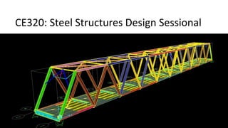
These slides give a short summary for the design of a truss bridge as a part of Steel Structures Design Sessional for the Course CE 320.

Empfohlen
Weitere ähnliche Inhalte
Was ist angesagt?
Was ist angesagt? (20)
Ähnlich wie CE 320 Steel Structures Design Sessional slides
Ähnlich wie CE 320 Steel Structures Design Sessional slides (20)
Mehr von nazifa tabassum
Mehr von nazifa tabassum (9)
Kürzlich hochgeladen
Kürzlich hochgeladen (20)
CE 320 Steel Structures Design Sessional slides
- 1. CE320: Steel Structures Design Sessional
- 3. Longitudinal Elevation Top/Bottom Bracing Deck System Cross Bracing Diagonal Bracing Floor Beam Stringer Top/Bottom/Diagonal Cord 10 @ 28 ft = 280 ft
- 4. Double Angle Portal Bracing 32 ft 30 ft 4 @ 6 ft 24 ft 3 ft 3 ft Cross Section Built-up Box Section (Truss Member) Built-up W Section (Floor Beam) Rolled W and I Section (Other Elements)
- 5. Bridge Deck Precast Concrete Cast-in-situ Concrete Precast Concrete Deck Cast-in-situ Concrete Floor Beam
- 6. Loads on the Bridge Dead Load (considered for this class): Wearing surface (30 psf) 8 in Concrete deck (100 psf) Sidewalk (250 lb/ft) and Railing (25 lb/ft) Self weight of Stringer (Rolled W Section) Self weight of Floor Beam (Built-up W Section) Self weight of Truss Element (Built-up Box Section) Self weight of Top & Bottom Bracing System (Rolled W Section) Live Load (considered for this class): Vehicular Load Wind Load (As point load according to BNBC) Live Load Impact (Impact Faction, I = 50/(125+L) ≤ 0.3 )
- 7. Vehicular Load Design Truck Load (HS 20) Design Lane Load (HS 20)
- 8. Wind Load as per BNBC • BNBC Chapter 6, 2.4 • Table 6.2.20 –”Overall Pressure Coefficient CP for Trussed Towers” • Lohalia river, Patuakhali, 260km/h (Odd rolls) • Surma river, Kanaighat, Sylhet, 195km/h (Even rolls)
- 17. Modeling in SAP
- 18. Plan at top level Plan at bottom level
- 20. Initial sections to start: Truss Member • Material grade: Fy=345MPa • Top chord: Box section 600x450 » Thickness 16-30mm (assume 25mm initially) • Bottom chord: Box section 600x450 » Thickness 16-30mm (assume 25mm initially) • Diagonal: Box section 600x450 » Thickness 16-30mm (assume 25mm initially)
- 22. Initial sections to start: Portal Portal: Double angle 150x150x10
- 23. Initial sections to start: Bracing Bracings: I section, depth 300, width 250, thickness 10-12mm
- 24. Initial sections to start: Stringer Dead Load Moment, MDL = wL2/8 Dead Load Shear, VDL = wL/2 w is calculated as the dead load of the tributary Area and the self weight of the stringer (Assume self weight as 140 plf)
- 28. M = MDL + MLL + MIL V = VDL + VLL + VIL Sx = M/Fb Fb = 0.66Fy Identify W section based on Sx Check: fv = V/Aw ≤ 0.3Fy Aw is the area of the web
- 32. Initial sections to start: Floor Beam
- 43. Design
- 49. FATIGUE LOADS 1. Under service load conditions, majority of trucks do not exceed the legal weight limit. So it would be unnecessary to use the full live load model. Instead it is accommodated by using a single design truck with the variable axle spacing of 9m and a load factor of 0.75 as prescribed in table.[A3.4.1.1]. 2. The number of stress load cycles is based on traffic surveys. In lieu of survey data, guidelines are provided in AASHTO [A3.6.1.4.2]. The average daily truck traffic (ADTT) in a single lane may be estimated as ADTTSL = p(ADTT) Where p is the fraction of traffic assumed to be in one lane as defined in table4.3.
- 50. PEDESTRIAN LOADS • The AASHTO pedestrian load is 3.6 x 10⁻³ MPa, which is applied to sidewalk that are integral with a roadway bridge. • If load is applied on bridge restricted to pedestrian or bicycle traffic , then a 4.1 x 10⁻³ MPa is used. • The railing for pedestrian or bicycle must be designed for a load of 0.73 N/mm both transversely and vertically on each longitudinal element in the railing system.[A13.8 and A18.9]. • In addition as shown in the figure , the railing must be designed to sustain a single concentrated load of 890 N applied to the top rail in any direction and at any location.
- 51. DECK & RAILING LOAD • The deck must be designed for the load effect due to design truck or design tandem , whichever creates the most extreme effect. • The deck overhang, located outside the facia girder and commonly referred to as the cantilever is designed for the load effect of a uniform line load of 14.6 N/mm located 3m from the face of the curb or railing as shown in the figure. • The gravity load for the deign of deck system are outlined in AASHTO[A3.6.1.3.3]. • The vehicular gravity loads for decks may be found in AASHTO [A3.6.1.3].
- 54. Load Combination Limit State DC DD DW EH EV ES LCE BR PL LS WA WS WL FR TU CR SH TG SE Use one of these at a time EQ IC CT CV STRENGTH – I γp 1.75 1.00 - - 1.00 0.50/1.20 γTG γSE - - - - STRENGTH - II γp 1.35 1.00 - - 1.00 0.50/1.20 γTG γSE - - - - STRENGTH - III γp - 1.00 1.40 - 1.00 0.50/1.20 γTG γSE - - - - STRENGTH – IV EH, EV, ES, DW, DC ONLY γp 1.5 - 1.00 - - 1.00 0.50/1.20 - - - - - - STRENGTH – V γp 1.35 1.00 0.40 0.40 1.00 0.50/1.20 γTG γSE - - - - EXTREME EVENT – I γp γEQ 1.00 - - 1.00 - - - 1.00 - - - EXTREME EVENT – II γp 0.50 1.00 - - 1.00 - - - - 1.00 1.00 1.00 SERVICE - I 1.00 1.00 1.00 0.30 0.30 1.00 1.00/1.20 γTG γSE - - - - SERVICE – II 1.00 1.30 1.00 - - 1.00 1.00/1.20 - - - - - - SERVICE - III 1.00 0.80 1.00 - - 1.00 1.00/1.20 γTG γSE - - - - FATIGUE – LL, IM, AND CE ONLY - 0.75 - - - - - - - - - - - AASHTO (2007) LOAD COMBINATION AND LOAD FACTORS
- 55. • Service I : DL +(LL+IM) +0.3W +W on live • Service II: DL + 1.3 (LL+IM)