1. Topics: Network Topology
SUBMITTED BY:
Md. Naimur Rahman
Id: 1915002521
Batch: 50th
Department of CSE
City University
Topologoy
A Network Topology is the arrangement with which computer systems or network
devices are connected to each other. Topologies may define both physical and logical
aspect of the network. Both logical and physical topologies could be same or different in
a same network.
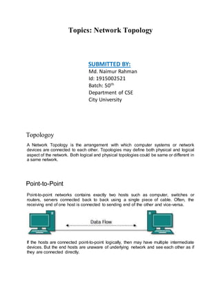
Point-to-Point
Point-to-point networks contains exactly two hosts such as computer, switches or
routers, servers connected back to back using a single piece of cable. Often, the
receiving end of one host is connected to sending end of the other and vice-versa.
If the hosts are connected point-to-point logically, then may have multiple intermediate
devices. But the end hosts are unaware of underlying network and see each other as if
they are connected directly.
2. Bus Topology
In case of Bus topology, all devices share single communication line or cable.Bus
topology may have problem while multiple hosts sending data at the same time.
Therefore, Bus topology either uses CSMA/CD technology or recognizes one host as
Bus Master to solve the issue. It is one of the simple forms of networking where a failure
of a device does not affect the other devices. But failure of the shared communication
line can make all other devices stop functioning.
Both ends of the shared channel have line terminator. The data is sent in only one
direction and as soon as it reaches the extreme end, the terminator removes the data
from the line.
Star Topology
All hosts in Star topology are connected to a central device, known as hub device, using
a point-to-point connection. That is, there exists a point to point connection between
hosts and hub. The hub device can be any of the following:
Layer-1 device such as hub or repeater
Layer-2 device such as switch or bridge
Layer-3 device such as router or gateway
3. As in Bus topology, hub acts as single point of failure. If hub fails, connectivity of all hosts
to all other hosts fails. Every communication between hosts, takes place through only
the hub.Star topology is not expensive as to connect one more host, only one cable is
required and configuration is simple.
Ring Topology
In ring topology, each host machine connects to exactly two other machines, creating a
circular network structure. When one host tries to communicate or send message to a
host which is not adjacent to it, the data travels through all intermediate hosts. To connect
one more host in the existing structure, the administrator may need only one more extra
cable.
4. Failure of any host results in failure of the whole ring.Thus, every connection in the ring
is a point of failure. There are methods which employ one more backup ring.
Mesh Topology
In this type of topology, a host is connected to one or multiple hosts.This topology has
hosts in point-to-point connection with every other host or may also have hosts which
are in point-to-point connection to few hosts only.
5. Tree Topology
Also known as Hierarchical Topology, this is the most common form of network topology
in use presently.This topology imitates as extended Star topology and inherits properties
of bus topology.
This topology divides the network in to multiple levels/layers of network. Mainly in LANs,
a network is bifurcated into three types of network devices. The lowermost is access-
layer where computers are attached. The middle layer is known as distribution layer,
which works as mediator between upper layer and lower layer. The highest layer is
known as core layer, and is central point of the network, i.e. root of the tree from which
all nodes fork.
6. All neighboring hosts have point-to-point connection between them.Similar to the Bus
topology, if the root goes down, then the entire network suffers even.though it is not the
single point of failure. Every connection serves as point of failure, failing of which divides
the network into unreachable segment.
Hybrid Topology
A network structure whose design contains more than one topology is said to be hybrid
topology. Hybrid topology inherits merits and demerits of all the incorporating topologies.
7. The above picture represents an arbitrarily hybrid topology. The combining topologies
may contain attributes of Star, Ring, Bus, and Daisy-chain topologies. Most WANs are
connected by means of Dual-Ring topology and networks connected to them are mostly
Star topology networks. Internet is the best example of largest Hybrid topology