SlideShare a Scribd company logo
1 of 74
Download to read offline
Tower Design using Etabs:
Chapter 1
Modeling & Analysis
1 | P a g e
ABSTRACT
Etabs is an abbreviation for “Extended Three- dimensional
Analysis of Building Systems,” it is the main engineering
integrated software that is used to analyze and design different
structural elements. This report will show you how to use the
commands in order to generate a structural building with respect
to the Codes & regulations used in UAE and generate results for
the design of buildings including high rise buildings.
Written by: Eng.Nada Zarrak
Checked by: Eng Ahmed Sameer Zarrak
2 | P a g e
Table of Contents:
ABSTRACT...................................................................................................................1
AutoCAD Stage: ........................................................................................................4
Etabs Stage:................................................................................................................6
Define:....................................................................................................................7
-Material Property:.............................................................................................7
-Frame Section Property: ...................................................................................8
-Slab Property: ...................................................................................................8
-Wall Property:...................................................................................................8
-Define Diaphragm: ...........................................................................................9
-Define Piers: .....................................................................................................9
-Define Spandrels*: ...........................................................................................9
-Define Load Patterns: .....................................................................................10
-Load Case: ......................................................................................................12
-Load Combination as per ACI 318-11: ..........................................................18
-Define Function:.............................................................................................23
-Define Mass source*: .....................................................................................24
-Define P-Delta*:.............................................................................................25
-Define Modal Case*:......................................................................................26
-Define Auto Construction Sequence Load Case*: .........................................27
Assign: .................................................................................................................28
Assign Joint Restraint:.....................................................................................30
Assign Piers: ....................................................................................................31
Assign Spandrels:.............................................................................................32
Assign Modifiers*:...........................................................................................32
Assign Release/Partial Fixity for Frame:.........................................................35
Run the Model: ....................................................................................................36
1- Standard Solver............................................................................................36
2- Advanced Solver..........................................................................................36
3- Multi-threaded Solver: Provide no accuracy of the computation................36
3 | P a g e
Display the Results: .............................................................................................37
Storey Base Shear: ...........................................................................................37
Modal Mass Participation Ratio: .....................................................................41
Torsion Irregularity:.........................................................................................42
Displacement of the building against Wind Load............................................47
Story Drift against Seismic Load:....................................................................50
Seismic Story Drift Check: ..........................................................................51
Wind Story Drift Check:..............................................................................52
Solving the Errors in Response Spectrum: ..........................................................54
General Notes: .....................................................................................................55
Errors in Etabs: ....................................................................................................56
Resolve instabilities:............................................................................................58
Definitions: ..........................................................................................................59
1. Slab Modeling Type:...............................................................................59
2. Wall Property Type:................................................................................59
3. Diaphragm Rigidity: ...............................................................................59
4. Property Modifiers:.................................................................................60
5. Spandrels:................................................................................................60
6. Seismic Load Pattern: .............................................................................61
7. Wind Load Pattern:.................................................................................63
Explanation about Wind Load Calculation in ASCE 7-10:.........................65
8. Spectrum Case: .......................................................................................67
9. Mass Source:............................................................................................68
10. P-Delta: .................................................................................................69
11. Modal Case: ..........................................................................................70
12. Auto Construction Sequence Load Case: .............................................71
Conclusion: ..................................................................................................................72
Special Thanks:............................................................................................................73
4 | P a g e
AutoCAD Stage:
1- Prepare your AutoCAD file in layers in order to ease the stage of drawings.
A- Divide your layers according to your structural elements
 Slab (mesh as ploy line)
To mesh the slab you either can draw them in AutoCAD or use any kind of
software such as Robot or Saap.
"Note that the size of mesh to be used shouldn't be less than 2 as our main use
of Etabs isn't about Slab analysis rather than only transferring the load and
reactions, so decreasing mesh size will slow the analysis procedure and will
have no use for our Design. One important note that the mesh should have min
of 3& max of 4 legs, 5 sided shapes cause errors in the analysis."
Figure 1: AutoCAD dwg, Slab mesh using Robot Software
5 | P a g e
 Beam (as line)
"Note that when drawing lines of beam it should be connected to the center of
the column, at the edge of the wall & its length divided with the mesh".
 Column (dot / represent its center)
 Wall (line)
"Note that the lines of wall and beams and the point of columns should be
connected to the slab mesh in order to have no warning on Etabs. Make sure
that you divide the wall according the division of the mesh so a realistic
structure is represented."
B- Save the AutoCAD file as DXF and check if the drawing is in "Meters."
"Note that you arrange your floors in such away similar floors are represented in
one dxf file and later on it will be replicated on Etabs."
Figure 2: AutoCAD dwg, Beam connected to Slab mesh 7 edge of the wall
6 | P a g e
Etabs Stage:
1- Open Etabs --> file-->new model-->use Built-in setting with "Metric" &
choose the Concrete Design code "ACI 318-11"-->ok. For example or other
Codes
2- Use the blank page --> custom story data: use elevation as given in the
AutoCAD plan--> and No Grid Spacing is needed.
Figure 3: Etabs2015 Model Initialization
Figure 4: Etabs2015 New Model Quick Templates
7 | P a g e
3- File--> Import -->DXF/DWG FILE OF ARCHITECTURAL PLAN --> unit:
m, factor:1
4- You can custom the stories going to Edit--> Edit stories and Grid System
5- Once your Main input is ready you can start Defining your element.
Define:
-Material Property:
Weight per Unit Volume = 25 KN/m3 for reinforced concrete
Modulus of Elasticity= 4700√𝑓′𝑐, f'c=0.8fcu
Design property data-->Modify-->Specified concrete Compressive Strength f'c
= 48 MPA if fcu = 60 MPA for example.
Figure 5: Etabs 2015 Material Property Data
8 | P a g e
-Frame Section Property:
Columns: "Note that you don't have to define the frame element as later on
while drawing it will be defined by itself. However you only have to make
sure that the "ConcCol" Material is same what you have defined in the 1st
step."
Beams: "Note you have to define your beams element unlike columns. So
name your beams and set the material property same as what you have
defined."
For this step you don't have o assign the framing Modifier property as later on
we will explain the use of the property and how to assign then in professional
way
-Slab Property:
Material = as what you have defined previously
Modeling type = Shell-thin *
Property Data Type = Slab
Thickness=26cm according to the usage of the slab for example.
-Wall Property:
Property Type= Specified*
Wall Material = what you have defined
Modeling Type= Shell-Thin
Thickness = according to your AutoCAD plan or the assumption.
9 | P a g e
-Define Diaphragm:
Diaphragm name= D1
Rigidity = Semi Rigid*
-Define Piers:
Add piers name according to the division of the wall in your structure.
This step can't be done unless the division of the wall has been drawn.
Later on it will be shown in the explanation below.
-Define Spandrels*:
Add Spandrels name according to the number of walls excited. This step
can't be done unless the division of the wall has been drawn. Later on it
will be shown in the explanation below.
Figure 6: Etabs2015 Diaphragm Data Semi Rigid
10 | P a g e
-Define Load Patterns:
a- Dead: which represent the own weight of the elements with self multiplier=
1 which is mean that the program assign it by itself.
b- Live load: depends on the usage of the structure, you can refer to BS code,
ACI code or Authority Regulation. For residential use LL=2kn/m2.
c- Finish= super dead
d- Stair line load = other
e- Temperature = Temp (used when the width or length of the building >=50m
or as per Authority Regulations.
f- Seismic (lateral force) * "ex" &"ey" = seismic, according to the authority --
> UBC97 is used --> Modify Lateral Load:
11 | P a g e
"Note that we only need to define the static dynamic load for the reason of equalizing
the base shear value that later on will be explained."
g- Wind* = type: wind --> Code: ASCE 7-10-->Modify Lateral load-->
12 | P a g e
-Load Case:
Since load pattern has been defined, Etabs automatically defines the load case
type of the patterns as linear static, However additional Load Case will be
added for the P-delta Analysis of the structure and later on its result will be
compared with the static seismic load, it is called Spectrum*.
"Note you have first to define "Function" before you add the load case,
you can check this step as shown in the Define section below in this
report"
Four cases will be defined two in different direction but with a Diaphragm
Eccentricity = 0 and the other two with Diaphragm Eccentricity = 5%
CASE 1: Spec-x
- Load Case type: Response Spectrum
- Load type: Acceleration
- Load name: U1(x-direction) & U3 (z-direction), added to count for UZ for
the Modal Mass Participation ratio.
- Function: "as you have defined"
Figure 7: Load Patterns
13 | P a g e
- U1 Scale Factor: = g*I/R, {g = ground acceleration, I=importance factor,
R=reduction factor, same value used for static seismic load define} =
9.81*1/5.5
- U3 Scale Factor = (2/3)*U1 scale factor.
"Note that you can apply any value of scale factor because later on it will be
changed when compared with the static dynamic load you can have a scale
factor =1000 for example."
- Diaphragm Eccentricity: 0
CASE 2: Spec-y: same procedure is done however with load name = U2
CASE 3: Spec-x-1
- Load Case type: Response Spectrum
- Load type: Acceleration
- Load name: U1 & U3
- Function: "as you have defined"
- U1 Scale Factor: = g*I/R, {g = ground acceleration, I=importance factor,
R=reduction factor} = 9.81*1/5.5
- U3 Scale Factor = (2/3)*U1 scale factor.
- Diaphragm Eccentricity: 5% or 0.05.
CASE 4: Spec-y-1: same procedure is done however with load name = U2 and
Diaphragm Eccentricity = 5% or 0.05.
"Note that Load Case Spec-xy is used in case the structure shape was
irregular."
14 | P a g e
Figure 8: Load Case 1, Spec x
15 | P a g e
Figure 9: Load Case 2, Spec y
16 | P a g e
Figure 10: Load Case 3, Spec x-1
17 | P a g e
Figure 11: Load Case 4, Spec y-1
18 | P a g e
-Load Combination as per ACI 318-11:
S: service load
U: ultimate load
DL: summation of all dead load
LL: summation of all live load
S1 = DL+0.75LL+0.75TEMP
S2=DL+0.75LL-0.75TEMP
S3=DL+WIND
S4=DL+0.7 SPECx
S5=DL+0.7 SPECx1
S6=DL+0.7 SPECy
S7=DL+0.7 SPECy1
S8=DL+0.75 LL + 0.53 SPECx
S9=DL+0.75 LL+ 0.53 SPECx1
S10=DL+0.75LL+0.53 SPECy
S11=DL+0.75LL+ 0.53 SPECy1
S12=DL+0.75LL+0.75 WIND
S13=DL+0.75LL-0.75 WIND
S14=0.6DL+WIND
S15=0.6DL-WIND
S16=0.6DL+0.7 SPECx
S17=0.6DL+0.7 SPECx1
S18=0.6DL+0.7 SPECy
S19=0.6DL+0.7 SPECy1
S20=DL
S21=DL+LL
S22=DL+LL+TEMP
S23=DL+LL-TEMP
ENVELOPE SERVICE= all Service load
Load combination type: Envelope
19 | P a g e
-------------------------------------------------------------
U1=1.2DL+1.6LL+1.2TEMP
U2=1.2DL+1.6LL-1.2TEMP
U3=1.2DL+1.6LL+0.8WIND
U4=1.2DL+1.6LL-0.8WIND
U5=1.2DL+LL+1.6WIND
U6=1.2DL+LL-1.6WIND
U7=1.4DL
U8=0.9DL+1.6WIND
U9=0.9DL-1.6WIND
U10=1.2DL+LL+SPECx
U11=1.2DL+LL+SPECx1
U12=1.2DL+LL+SPECy
U13=1.2DL+LL+SPECy1
U14=0.9DL+SPECx
U15=0.9DL+SPECx1
U16=0.9DL+SPECy
U17=0.9DL+SPECy1
ENVELOPE ULTIMATE= all Ultimate load
Load combination type: Envelope
ENVELOPE ULTIMATE (SPECx) = all Ultimate load for
SPECx
Load combination type: Envelope
ENVELOPE ULTIMATE (SPECy) = all Ultimate load for
SPECy
Load combination type: Envelope
"Note that Two Envelope Combos were added for both direction of SPEC in
order to check the Drift accordingly."
20 | P a g e
"Note: another Model will be represented for Wind drift Checking:
Load Combination":
Wind Drift = DL+0.5LL+0.7 WIND --> X direction
= DL+0.5LL-0.7 WIND --> Y direction
This model will have no release for the column and according to UBC 97 you
will multiply modifier 0.7(for column) by 1.43 =1
Figure 12: ASCE 7-10, Commentary Appendix C
21 | P a g e
Once you have finished this step it is important to Check the model in
case any overlapping in the mesh appears ->
Go to Analyze-->Check model --> Length Tolerance of check = 0.00001 or
you can increase the length for more accurate checking. Don't forget to
choose all the selections.
Figure 13: Check Model command
22 | P a g e
P-Delta Analysis:
As shown in the figure the name p delta is driven out by the effect of P
(Normal force, the force generated at the top and bottom of the column) *
delta (horizontal displacement) and the result is the Moment which will cause
a lateral deflection. The effect of P delta is severe in case of resisting moment
frame system in high rise building when an earthquake is applied. P delta
generates additional shear force and bending moment in columns so the
structure should be sufficient to shear resistance in addition to the earthquake
shear otherwise the building may fall down.
To start defining P delta analysis:
23 | P a g e
-Define Function:
Response Spectrum --> add new function "make sure function type is
according to the code used"
-->seismic coefficient, Ca =0.24
-->seismic coefficient, Cv =0.32
Those coefficients are driven from the static Seismic load definition in the
previous step.
-->ok
Figure 14: Function parameter
24 | P a g e
-Define Mass source*:
Add mass source name--> modify-->
Figure 15: Mass Source Parameter
25 | P a g e
-Define P-Delta*:
Iterative-Based on loads--> Dead loads = 1.2, Live Loads=0.5
Figure 16: P-Delta Load Combination
26 | P a g e
-Define Modal Case*:
Figure 17: Modal Case parameter
27 | P a g e
-Define Auto Construction Sequence Load Case*:
Figure 18: Auto Construction Sequence Case
28 | P a g e
Assign:
6- Once you have finished the Define bar you can start drawing using the Assign
menu: This step is the most important step for the Output of the Design.
-Note that arranging the layers in AutoCAD will now help you to draw the
element easily on Etabs2015.
Start by the Slab element --> at the left bar choose Draw floor
-->choose the property defined previously-->in the left bar: Model Explorer --
> Display --> View -> Architectural plan -->Layer Slab--> right click --
>Assign Area. You will notice that the mesh element has been drawn easily
with the slab property chosen.
"Note that you have to understand that the slab was already divided in a mesh
with size 2 as done in the previous step which means that we have to remove
the default of the Etabs2015 for the slab mesh as if that step didn't go correctly
it will consume time for the finite element analysis as the Etabs will re-divide
our manual mesh into smaller mesh --> an important step has to be done
before continue drawing other elements.
Go to Select all --> Assign --> Slab Automatic Mesh --> None."
-The Same procedure is done for Column and Beams. However for wall
element I prefer to draw them manually. Make sure the Snap option is on so
when drawing wall element it will be connected with the slab node.
-Since beams were drawn from center to center of columns-->don't mind that
the position of the beam isn’t at the right location because in Etabs it will be
moved to its original position using “insertion point”. First make sure that the
beams are intersecting properly.
"Note: if two beams intersect and to make sure that they meet at a point--
>select the two beams-->edit-->divide frame --> now to make sure that they
are intersected three beams should appear."
29 | P a g e
Insertion point is used to reposition the beam to its original location while it's
still drawn from center to center of column this step is done for showing the
result with the eccentricity of the beam.
Select the beam. Right click  go to design in the same window open
insertion point  and see where you want to move the beam at which edge I:
x or I: y, you can see how much to move in AutoCAD that will move the beam
the place you have in AutoCAD however it is still defined in the center of the
column  to show how they moved “Extrude Frame”.
7- The next important step is to start dividing the Shear wall using elevation as it
will represent the mesh of wall
Start naming the elevation according to your plan. To start drawing go to
Draw --> Draw Developed elevation-->name it-->ok
Then using the arrow, draw at the center of the wall starting from a point and
ending with a point "make sure you draw the line with the center of wall in
order to appear in the elevation plan."
Now the Elevation will show you the cross section of the wall --> for each
floor you will select and divide in such a way all the points meet at the same
line so in errors appear.
This Step is considered somehow a long one as you have to divide the walls in
such a way the length of the door is then to be removed from the wall section.
Using move joint command could be helpful.
"Note that the default of the wall mesh is none so it means our own division of
the wall is the mesh not like what we have done previously with the slab
mesh."
Since all your structural elements are drawn, it is time to start assigning the
main factors for your design analysis.
30 | P a g e
Assign Joint Restraint:
Since we are using piles as a foundation, joint will have a fixed support
assignment.
Go to plan-->Base-->select all the joint --> go to Assign-->Joint
-->Restraint-->Fixed (1st
select from the left side)
Figure 19: Joint Restraint
31 | P a g e
Assign Piers:
Assigning piers is very important for the wall design. Walls at the same
alignment in different floors should have the same pier name.
Go to Select--> select according to your appropriate type of selection--
>Assign-->Frame-->Pier name
32 | P a g e
Assign Spandrels:
Spandrels are assigned to the walls above the doors in the shear wall.
Go to Select--> select according to your appropriate type of selection--
>Assign-->Frame-->Spandrel name
Assign Modifiers*:
According to ACI 318-11, chapter 10, each structural element has a property
Modifier:
Figure 20: Property Modifiers according to ACI 318-11
33 | P a g e
To Assign Stiffness Modifiers:
Select (Slab) for example -->Assign  shell  Section modifiers.
(f11=f22=f12=m11=m22=m12) = 0.25 for flat slab and 0.5 for PT slab.
34 | P a g e
For Frame (Column) -->Assign-->Frame-->Property Modifier=0.7
For Frame (Beam) -->Assign-->Frame-->Property Modifier=0.35
35 | P a g e
Assign Release/Partial Fixity for Frame:
According to the Municipality both ends of the column need to be released
which means that the column will not be designed to handle the Seismic
Forces.
Go to  Select-->selectobject type Column.
Go to Assign-->Frame-Release/Partial Fixity 
Release Moment by selecting the options for start point & end point
Figure 21: Moment Release for Frame
36 | P a g e
Run the Model:
Go to Analyze--> Advanced SAPfire option -->
There are three Solving Method Options:
1- Standard Solver: this option is very useful for cases where model fails
under p-delta analysis. Using this option will show you the nodes that are free
or not connected to the mesh or wall. Such warnings will cause instabilities in
the structure and thus fails in p delta.
2- Advanced Solver: this is the program default solver option however it
doesn't show the lost of digits or free nodes.
3- Multi-threaded Solver: Provide no accuracy of the computation
"Note: Always start with the standard solver so you can fix the nodes that
didn't show in the check model."
37 | P a g e
The Main analysis results to be checked are:
a. Storey Base Shear
b. Modal Mass Participation Ratio
c. Torsion Irregularity
d. Displacement & Story Drift
“Note that the run should not take a long time otherwise it means that there is an error
in the modeling which is taking time for Etabs to solve.”
Display the Results:
Story Base Shear:
It is the total Lateral Force or shear at the base.
38 | P a g e
Once you have run the analysis, go to  Display  story Response plots 
Display type: Story Shear
“Note before you choose the Case/Combo you have to make sure that Modal
case appears so it means that the p delta analysis has been generated”
 Case/combo: EQx Read the value: Snapped to: and write it down, Do
the same procedure for Case/Combo: SPECx
Now These two values have to be same, if they aren’t then you have to divide
the Static load (EQx) over the Dynamic load (SPECx) to find the ratio that
need to be multiplied to the Scale Factor that was added.
Go to Define  Load Case  Spec x  Modify  Scale factor: Multiply
the Ratio (
𝑥
𝑥
)with the value written previously (U1&Uz) Rerun the
Analysis
"Note that you have to do the same thing for SPECy and EQy."
39 | P a g e
40 | P a g e
41 | P a g e
Modal Mass Participation Ratio:
Go to Display --> Table --> Analysis --> Results --> Modal Results --> Modal Mass
Participation Ratios.
Go to the last Mode number --> Sum Ux, Sum Uy & Uz = 90% or more according to
ASCE 7-10, Section 12.9.1
"Note that in Case Sum of Ux,Uy and Uz is less than 90% you have to increase
number of Modes, However note that increasing to many numbers of mode may
indicates that there is an error in the structure. Try to Check the Model in case there is
any error in the mesh, or the Diaphragm is not assigned to all mesh elements."
Figure 22: Modal Mass Particiption ratio as per ASCE 7-10, Section
12.9.1
42 | P a g e
Torsion Irregularity:
Since we are studying the structure due to earthquake load, it is important to check the
modal against torsional behavior during an earthquake. It is a result of eccentricity of
seismic forces. Torsional Irregularity mainly exists if structural building undergoes
earthquake and wind force (horizontal forces) which means that the building should
be checked if any torsional irregularity appears. According to ASCE 7-10 & UBC 97,
torsional irregularity appears when maximum story drift over average story drift is
more than 1.2 {(
𝑚𝑎𝑥
𝑎𝑣𝑔
) > 1.2}.
Figure 23: Torsion Irregularity as per ASCE7-10, Section
12.8
43 | P a g e
Figure 24: Torsional Amplification Factor as per ASCE 7-10, Section 12.8
Figure 25: Torsional irregularity as per UBC 97, Table 16-M
44 | P a g e
To check if the Ratio is more than 1.2 or less, Go to Display --> Show Table --
> Results --> Displacement--> Diaphragm Max/ Avg Drifts --> Choose load
Case Spec x or y --> check the Ratio
For Cases where the Ratio is more than 1.2 and less than1.4--> Torsional Irregularity
should be solved:
1- Prepare an Excel sheet where you have to insert these values according to the
floors with the torsional irregularity:
U max: to get the value --> go to Display --> Deformed Shape --> Case: Spec x -->
check the value at the left or right side of the floor and get the maximum value.
45 | P a g e
U min: will be the lower value of the left or right side of the floor
Uavg = (Umax+Umin)/2
Umax/Umin = get the value from the table = Ratio or calculate it using Excel
EccNewRatio =
𝑎𝑡𝑖𝑜
.
∗ 0.05
EccNew (m) = in Etabs the new value of eccentricity will be added in meters, to get
the value --> for X direction you will multiply the New Ratio will the vertical
dimension of the floor.
As shown in the figure, the black line represents the vertical dimension of the floor
according to the direction of the displacement.
46 | P a g e
To insert the new value of Eccentricity:
1- Go to Define --> Load Case --> Spec x o y according to what direction you choose
to start with.
2- Diaphragm Eccentricity --> Modify/Show -->
3- Add the Stories that require the new Eccentricity as shown in the figure above.
4- Note that same procedure should be done for the other direction.
47 | P a g e
Displacement of the building against Wind Load
Open the Model of wind drift in order to check lateral deflection of the building. Both
Direction of wind load will be compared with the Max allowable lateral deflection.
Go to Display --> Deformed shape -->
Figure 26: Etabs2015 Deformed Shape, Wind Drift X
48 | P a g e
Go to Last floor and make sure Joint is enabled from visible object --> Check Node
from up and down of the floor (Ux)
49 | P a g e
The two figures show the Ux at up end and left end --> taking max value of Ux and
compare it with (L/500) as per ASCE 7-10, CC.1.2. (L/500) is the value used in
general. Same procedure will be done for the other Direction.
Figure 27: ASCE 7-10, CC.1.2 Drift of Walls and Frames
50 | P a g e
Story Drift against Seismic Load:
It is the Lateral Displacement of one level relative to the other level above or below.
Note that Drift due to Seismic and Wind should be checked in separate models.
Determine of Drift depends on the load combination and period of recurrence. Since
seismic force is already factored, factor is always 1 in the load combination of ASCE.
The recurrence period of seismic force is 50 years. However for wind drift, 50 years
wind is converted to 10 years service wind force as recommended by ASCE cc.1.2.
Note that the UBC 97, Section 1630.10 Story Drift Limitation says that if the period
of the structure (T) was less than 0.7 second then the maximum story drift shall not
exceed 0.025*story height. While if the period (T) was more than 0.7 then a limit
of0.02*story height is used.
Figure 28: UBC 97, Section 1630.10 Story Drift Limitation
51 | P a g e
To check from Etabs the period of the structure:
Go to Display--> Show Table-->Results--> Modal Results --> Modal Periods and
Frequencies:
From Figure above Mode 1 shows a period of 2.994>0.7 second --> 002*story height
is used.
Drift will be checked against the two Lateral loads (Wind & Seismic)
Seismic Story Drift Check:
Starting with the Seismic Story Drift Check, an Envelope Load combination of
SPECx and SPECy was made from the previous steps. This Load Combination will
help in finding the worst case of the Spectrum to check for story drift.
To check Story Drift from Etabs:
Go to--> Display--> Show Table --> Results-->Displacement--> Story Drift-->
choose load combo "Envelope SPECx" --> Choose Direction X
The Table will show the Ratio of Drift which you will compare it with the Allowable
Story Drift Ratio (0.02) as per ASCE 7-10, Table 12.12-1. Note that our Risk
Category is ІІ as per ASCE 7-10, Table 1.5-1.
"Note that Etabs show the Ratio which represent (Point value at story x - Point value
at story below or above for the same point). If this ratio was multiplied by the story
height it will give the value which you will compare it with 0.02*h."
The same check should be done for the Y direction.
Figure 29: Etabs 2015, Modal Periods and Frequencies, Mode1
52 | P a g e
Wind Story Drift Check:
Open the model you named previously as Wind drift and recheck the wind drift Load
combination from Section Load Combination in the previous steps.
To check Story Drift from Etabs:
Go to--> Display--> Show Table --> Results-->Displacement--> Story Drift-->
choose load combo "wind drift x" --> Choose Direction X
Figure 31: Etabs 2015, Story Drift checking by Wind Drift in X direction
Figure 30: Etabs2015, Story Drift Checking by Ultimate Envelope Spec X
53 | P a g e
Figure 32: Allowable storey drift as per ASCE 7-10, Section 12.12
Figure 33: ASCE 7-10, Chapter 1, Table 1.5-1 Risk Category
54 | P a g e
"Note that if there are stories showing excessive values of story drift, it is because the
node or point at that location is not connected to the slab mesh or column. Modeling
technique should be drawn well otherwise it will cause unrealistic values of drift and
in other results".
Solving the Errors in Response Spectrum:
1- When you run the analysis go to last run analysis in order to show how many
Eigen value below the shift this indicates that the structure is instable
2- Increase first the section of the walls or columns.
3- Make sure that there is no additional story, for example if you used to have 30
stories and you want only 29 stories go to modify grids and delete that story
as it affects the analysis of the spectrum.
4- In order to check that all the members are connected together and there is no
element outside the mesh that could affect the stability, go to “start
Animation” and see the behavior of the elements.
55 | P a g e
General Notes:
1- Should twin tower be modeled separately in Etabs? The answer is yes
because the twin towers are separated by an expansion joints at the podium
level  there is no load transfer between them + we perform dynamic
analysis which requires us to have different load scale factors for each
tower.
2- In case you want to rotate the model select the Model  Edit 
Replicate  Radial  Choose the angel of rotation.
3- In case the objects weren’t shown it means you have to go  View 
show all object. And make sure that in the option all the layers are ticked.
4- Note in case load case Spec didn’t show in the story response plot after
running  Reassign the Diaphragm and recheck the mesh as it is the main
reason of the instability make sure that no mesh is assigned to the slab as
we already draw them meshed.
5- In case you import a drawing and when you want to draw it doesn’t snap
 draw  snap option  Select all  apply.
6- Note if you want the modal to run for a specific load case  Analysis 
Set load case to run  and choose whatever load cases you want to run
for.
56 | P a g e
Errors in Etabs:
1- Beams “are too close” it means you have to:
a- Draw in AutoCAD from center to center of column
b- In case beams intersecting  draw them in AutoCAD in such a way
the “green rectangular sign appears” when drawing from line to line
that means they are drawn connected.
c- Try to find the geometry in Etabs of the two beams that there y or are
the same
d- Or use the Move command from the Edit menu
e- Another way is that you select the two beams and then Edit--> Edit
frame--> Divide frame -->
If the two beams became three beams it means that the beams are now
connected at one point.
2- Slabs are too close, you have to read in which floors, note that in case you
have different slabs in one floor, overlapping could happens  you have to
read the joint label and check the geometry in such a way slabs wont
overlap.
57 | P a g e
3- If there was an error saying with beam and joint then try to either move the
joint to the beam or vice versa using also the copy from geometry of the
point or the beam or paste it in the other geometry.
4- If you run the model and P delta analysis didn't solve --> it means that
there's Instability in the structure --> Run the Model for Standard solver
option--> Check the nodes given in the detail & write their location -->
usually these nodes are connected to the mesh--> try to redraw the mesh or
move the node to the mesh.
5- If running the Model takes a long time make sure that you have assigned
"No Auto mesh" for slab as they are already meshed manually.
6- Make sure that you have defined a mass source as it affects the p delta
analysis.
58 | P a g e
Resolve instabilities:
a. Run log – After analysis, ensure that the model is stable by checking the analysis log,
available through File > Last Analysis Run Log.
b. Dead load – Review the animation of deformed configuration under self-weight to
ensure reasonable response from gravity loading.
c. Mode shapes – Run modal analysis to verify that each mode-shape period is
reasonable. Especially long periods will indicate instability. Animate the deformed
shape of an unstable mode to identify the location of instability, then edit the model to
resolve convergence problems.
d. Restraints and constraints – Do not restrain DOF that are associated with
a constraint.
e. Release only one end – Ensure that releases are not assigned to both ends
of frame objects. Releasing both ends may prevent load transfer, leading to numerical
problems. Information on numerical problems is available using the Standard Solver,
available through Analyze > Set Analysis Options > Solver Options.
f. Avoid full fixity and full rigidity – Rather than applying full fixity to DOF and full
rigidity to structural objects, restrained and rigid conditions should be modeled using
sufficiently large stiffness values, perhaps on the order of 1e11, or 1e3 to 1e4 times
the stiffness of nearby members. Stiffness values may be assigned using spring
constants, property modifiers, or section properties. Full fixity or full rigidity may
cause numerical sensitivity in linear solutions and singularities in nonlinear numerical
formulation, leading to convergence problems or instabilities.
Reference: https://wiki.csiamerica.com/display/kb/Troubleshooting+Checklist
59 | P a g e
Definitions:
1. Slab Modeling Type:
Membrane: used to represent in plane stiffness of members which means that is
it has no bending resistance
Shell: they have in plane and out plane stiffness thus they are more realistic for
any structural slab.
Note that in Shell type we have thin and thick shell it is important to
differentiate between them usually thick slab used for raft foundation while in
our case of the tower design we will end up using thin-shell.
If you want to know more about the difference you can read the book "Theory
and analysis of elastic plats and shell- J.N.Reddy"
One important note about the difference between membrane and shell is that
membrane transfer 100&% of the forces to beam and doesn't take any part of
load bearing thus representing slab as shell will act both as load bearing and
transferring load to the support.
2. Wall Property Type:
We have both Specified and Auto Select List, when the Auto Select List is used
the program then will use the thinnest wall property to satisfy both the strength
requirements and the lateral drift thus in our Design we have to use Specified
so we can specify the wall property.
3. Diaphragm Rigidity:
The importance of assigning Diaphragm is mainly to distribute the seismic
forces as it connects all individual members into seismic force Resisting
System. This means that we connect all the elements in order for the structure
to act as one mass.
Rigid: it means it's infinitely rigid which doesn't deform & it distributes forces
based on connecting member’s stiffness. It is used in case we have thick slab
and lateral deformation is negligible
Semi-Rigid: it distributes the loads based on the tributary area of the supports.
It is used in case lateral deformation is significant just like towers
60 | P a g e
No diaphragm or Flexible diaphragm: means there's no diaphragm used to
distributes the lateral forces it's also called flexible as it allows the frame to
deflect independently of other connecting member
4. Property Modifiers:
Stiffness Modifiers are factor used to decrease or increase property of the cross
section. They are used to represent the behavior of the structure in cracked
stage "Cracking of the RCC sections." According to ACI 318 if P-delta analysis
is used it is important to use the cracked section for the deformation calculation
and strength of the section.
5. Spandrels:
This photo here shows how spandrel is being assigned. Note that walls at the
same alignment have same spandrel names.
Spandrels usually marked for the bracing between walls above the doors.
Figure34:https://wiki.csiamerica.com/display/etabs/Pier+and+Spandrel+Labeling+and+Design
61 | P a g e
6. Seismic Load Pattern:
-Direction & Eccentricity: you only need to select X-Dir as for dynamic analysis the
only purpose of defining Static load of earthquake is to equalize it with the base shear
as shown in the previous steps.
-Time period Ct (ft): Program Calc = 0.02
-Importance Factor, I: According to UBC 97, Table 16-K, I = 1
-Over Strength Factor, Ductility factor or Force Reduction Factor, R: this factor is
very important as it represent how much the reduction of the force will happen
according to the usage and importance of the structure. In case we have Hospitals,
R=1 however this means it will cost more as the structure will be designed to face
almost no cracking after an Earthquake such buildings are called “Essential
Buildings” or “Special”.
R= Elastic/Inelastic
According to UBC 97-Table 16-N-Structural System, Concrete Shear Wall, R=5.5
Figure 35: UBC 97, Table 16-N, Structural Systems
62 | P a g e
-Damping Eccentricity = 5%: According to UBC 97 damping eccentricity of 5% is used for
the uncertainty of the design and construction. It means that at Site sizes of columns or beams
are not 100% exact as per design. It is considered for Safety issues however in our dynamic
analysis it doesn’t matter as we are not designing our tower due to static load.
-Soil Type Profile: SC
-Seismic Zone Factor = 0.2
Figure 37: UBC 97, Table 16-1 Seismic Zone factor Z
Figure 36: UBC97, Table 16-j, Soil Profile Types
63 | P a g e
7. Wind Load Pattern:
-Exposure and Pressure Coefficients: choose "Diaphragms." This option allows
the same wind load to be applied each time the load case is assigned.
-Wind Pressure Coefficients: Program Determined
- Wind Exposure Parameters: Create all sets (it will consider the four load
cases as mentioned in ASCE 7-10, figure 27.4-8.
E1 ratio= 0.15
E2 ratio= 0.15, According to ASCE 7-10, Figure 27.4-8
Figure 38: ASCE 7-10, Figure 27.4-8, Design Wind Load Cases
64 | P a g e
- Wind Speed (mph) =101 as per ASCE7-10 maps
-Exposure Type: B
-Gust Factor: usually a value of 0.85 is assigned however it is important to
assign the value required according to the frequency of the structure.
1- Save the model and name it for "Wind Drift"
2- Assign a frame modifier = 1, and don't Release Fixity of Frames.
3- Run the Model
4- Display period of the structure, Display --> Show Table --> Results-->
Model Result--> Modal Periods and Frequencies
5- The table will show the number of modes added with the period in sec, however
the first two modes are always the ones with the larger values. Mode 1 represents the
period in X direction and Mode 2 represents the period in Y direction.
6- Using Excel sheet, insert the value of T1 or T2 and take the worst value of the Gust
Factor.
"Note that value greater or near to 1are considered a worst case"
65 | P a g e
Explanation about Wind Load Calculation in ASCE 7-10:
- Chapter 27 talks about wind load calculation
- Chapter 26 talks about general requirements
There are three methods for wind force calculation:
METHOD 1: Envelope Procedure MWFRS, C&C (Simplified Method 2 Low-Rise)
MWFRS: Main Wind Force Resisting System
METHOD 2:
1- All-Heights: Directional Procedure MWFRS, C&C
2- Low Rise: Envelope Procedure MWFRS, C&C
METHOD 3: Wind Tunnel Procedure
----------------------------------------------------------------------
- SECTION 26.1.2 talks about permitted procedure
-Section 26.1.2.1 talks about Directional & Envelope Procedure MWFRS
-Section 26.2 explains Definitions
-Section 26.3 explains Symbols
-Section 26.4 shows Sign Convention
+ (force toward surface)
- (away from surface)
-Section 26.5 shows wind Speed maps (depends on Risk Category)
We have 4 risk categories
For Risk 1  table 1.5-1 page 2
For Risk 2  page 247a, 247b
USUALLY RESIDENTIAL BUILDINGD HAVE RISK CATEGORY 2
-Section 26.7 talks about Exposure type
66 | P a g e
-Section 26.7.2 talks about surface roughness
B (urban or woods), C, D (flat and wide) such as if you live in cost or desert or shore
line
-Section 26.8 shows topography effects, wind speed up over hills, ridges etc.
K1, K2, K3  figure 26.8 -1
And if there is no hills  kzt = 1.0
-Wind gust  if building is rigid, gust effect factor will decrease load 0.85
Building rigidity depends on natural frequency of the building
(Usually all low rise building are considered rigid)
A low rise building:
1- Height less than 60 ft.
2- Height must be less than either of width or length of the base
-Section 26.10 talk about Enclosure (means hole or opening in the building)
1- Enclosed
2- Partially Enclosed
3- Open (at least 25% of wall is opened by glass or door)
-Section 26.11 talks about Internal pressure  table 26.11-1
Gcpi: = 0 for open
(- or +) 0.55 for partially open
(- or +) 0.18 for enclosed
Chapter 27: discusses MWFRS –directional procedure, Table 27.2-1 gives procedure
for calculation p260
-Section 27.3 = velocity pressure  it converts wind speed into pressure on the
building
AND FROM PRESSURE we will get wind load.
67 | P a g e
8. Spectrum Case:
Seismic Force Calculation:
1- Static Method: defining static load Ex & Ey
2-Dynamic Method, defining Modal Response Spectrum: is a method used to
determine Seismic response of a structure. 5% damping is used to determine response
spectrum curve.
3- Time History: gives response of the structure for a given periods and it depends on
the previous data.
----------------------------------------------------------------------------------------
For our Analysis Dynamic Method is used. Response Spectrum analysis or (Multiple
Model Response Spectrum analysis) is a linear dynamic statistical analysis method
which measures from each mode of vibration to indicate maximum seismic response
of an elastic structure. For High rise buildings it's not possible to predict seismic
behavior with single mode that is why we consider multiple mode cases which is used
for dynamic analysis.
Figure 39: Modal Response Scale Factor per ASCE 7-10, Section 12.9
Figure 40: Modal Combined Method as per ASCE 7-10,Section 12.9
68 | P a g e
9. Mass Source:
For Earthquake weight calculation, Mass source need to be defined in order for
Etabs to calculate it correctly so Mass source represent the Seismic weight that
will be used for the seismic calculation. Such step is important in order for Etabs
distributes the seismic load correctly. It will consider a full dead load with factor 1
and live load factor =0.25, why is that? During an Earthquake dead is left the same
which means that we will consider the whole weight of dead  factor =1, however
for residential building the only live load left is for example furniture and that's why
0.25 of live load is considered for weight calculation.
-Element self-mass: Etabs automatically add the mass of the structure by this
selection, if element self-mass was checked, don’t add Dead load in the Specified load
Patterns.
-Additional Mass: used to account for partitions, cladding and so on. However finish
load will be added in the Specified Load Patterns so no need to select.
-Specified Load Patterns: Only the global Z-direction loads are considered when
calculating the mass. This mass is applied to each joint in the structure on a tributary
area basis in all three translational directions.
-Include lateral Mass: assigned translational mass in global X&Y-axis directions and
rotational mass moment of inertia about the global Z-axis are considered in the
analysis.
-Include vertical mass: assigned translational mass in the global Z axis direction and
assigned rotational mass moments of inertia about the global X and Y axes are
considered in the analysis.
-Lump Lateral mass at Storey level: is checked when we have a transfer slab or
planter column.
(You can check CSI America documents for any reference.)
Figure 41: Effective Seismic weight as per ASCE 7-10,
Section 12.7
69 | P a g e
10. P-Delta:
-Iterative Based on Load Cases: loads are derived from combination based on static
load cases. These load combination is called P-Delta load Combination.
This method requires iteration of specified combination to determine P-Delta effect
on the structure. It considers local buckling effect more significantly more than the
non-iterative one.
P delta load Combination = 1.2DL+0.5LL
Figure 42: P delta effect definition as per ASCE 7-10, page 60
70 | P a g e
11. Modal Case:
Modal analysis is a linear dynamic response procedure used to calculate frequency
modes and showing displacement patterns of a structure.
"Modes: is a combination of a deformed shape of a structure depending on the
structure mass"
This step is important as it makes sure than more than 90% of the structure's mass in
Ux, Uy and Uz is participating under the effect of the lateral forces (Seismic Forces).
-Ritz: they are sufficient for dynamic analysis involving horizontal motion. "You can
learn more about the Ritz vector in the Etabs Manual." Ritz provide a better basis
when used for response spectrum
-Load Type: Acceleration
- Maximum Number of Modes = usually equal Number of stories in our structural
building.
Figure 43:Modal Mass Participation Ratio as per ASCE 7-
10,Section 12.9
71 | P a g e
12. Auto Construction Sequence Load Case:
It is used when we have a planted column or a transfer Slab--> Go to Define--> Auto
construction sequence case--> Check "Case is active" --> Load applied: add only
DEAD load as Live load will be applied after the Structure is complete. Deal Load
factor = 1.
Now Etabs will automatically generate a load case called Autoseq, you can
check by going to the load case in the Define menu.
72 | P a g e
Conclusion:
Now you can Model and analyze any kind of structural element with different
number of floors and shapes. Usually Seismic effect is the main concern to
handle throughout the design process. It's important to study about Dynamic
analysis in order to understand how the structure responds under lateral loads.
Reading, searching and questioning are your primary tools to a better structural
concept.
Make sure that every factor, ratio, & cases is based on the Code used in your
country. Never underestimate the importance of the regulations needed
throughout the design procedure.
And Last but not least Civil Engineering is definitely the mother of knowledge.
73 | P a g e
Special Thanks:
-Special thanks to my father who gave me support and encouragement to start
this work and completing it with this final report.
-Special thanks to my mother who believed that nothing is impossible.
-Special thanks to my brother Rami who provided the necessary tools and
software to start the Design process.
-Special thanks to every Engineer who helped in the process of learning and
understanding.
-Special thanks to my friends Ahmed, Ruaa, Noor, Shahd, Amani, Yuser, Zain,
& Rasha.
-Special thanks to everyone who is willing to learn, study and help in
improving the world.
For any Information, Questions or Doubts please contact:
Nada.Zarrak@hotmail.com

More Related Content

What's hot

Tutorial for design of foundations using safe
Tutorial for design of foundations using safeTutorial for design of foundations using safe
Tutorial for design of foundations using safeAsaye Dilbo
 
Etabs tutorial-tall-building-design (1)
Etabs tutorial-tall-building-design (1)Etabs tutorial-tall-building-design (1)
Etabs tutorial-tall-building-design (1)Nitesh Singh
 
Part-II: Seismic Analysis/Design of Multi-storied RC Buildings using STAAD.Pr...
Part-II: Seismic Analysis/Design of Multi-storied RC Buildings using STAAD.Pr...Part-II: Seismic Analysis/Design of Multi-storied RC Buildings using STAAD.Pr...
Part-II: Seismic Analysis/Design of Multi-storied RC Buildings using STAAD.Pr...Rahul Leslie
 
Etabs BY Subash Pathak
Etabs BY Subash PathakEtabs BY Subash Pathak
Etabs BY Subash PathakSubash Pathak
 
Part-I: Seismic Analysis/Design of Multi-storied RC Buildings using STAAD.Pro...
Part-I: Seismic Analysis/Design of Multi-storied RC Buildings using STAAD.Pro...Part-I: Seismic Analysis/Design of Multi-storied RC Buildings using STAAD.Pro...
Part-I: Seismic Analysis/Design of Multi-storied RC Buildings using STAAD.Pro...Rahul Leslie
 
Steel structures practical_design_studies_mac_ginley_2nd_ed
Steel structures practical_design_studies_mac_ginley_2nd_edSteel structures practical_design_studies_mac_ginley_2nd_ed
Steel structures practical_design_studies_mac_ginley_2nd_edThomas Britto
 
Overview of Direct Analysis Method of Design for
Overview of Direct Analysis Method of Design forOverview of Direct Analysis Method of Design for
Overview of Direct Analysis Method of Design forRyan Brotherson
 
Staad Pro Intro
Staad Pro IntroStaad Pro Intro
Staad Pro IntroSolai Raja
 
The Pushover Analysis from basics - Rahul Leslie
The Pushover Analysis from basics - Rahul LeslieThe Pushover Analysis from basics - Rahul Leslie
The Pushover Analysis from basics - Rahul LeslieRahul Leslie
 
Etabs installation and cracking procedure
Etabs installation and cracking procedureEtabs installation and cracking procedure
Etabs installation and cracking procedureRifat Bin Ahmed
 
Rc bldg. modeling & analysis
Rc bldg. modeling & analysisRc bldg. modeling & analysis
Rc bldg. modeling & analysisRamil Artates
 
How to model and analyse structures using etabs
How to model and analyse structures using etabsHow to model and analyse structures using etabs
How to model and analyse structures using etabsWilson vils
 

What's hot (20)

Tutorial for design of foundations using safe
Tutorial for design of foundations using safeTutorial for design of foundations using safe
Tutorial for design of foundations using safe
 
Etabs notes-pdf
Etabs notes-pdfEtabs notes-pdf
Etabs notes-pdf
 
CSI ETABS & SAFE MANUAL: Slab Analysis and Design to EC2
CSI ETABS & SAFE MANUAL: Slab Analysis and Design to EC2CSI ETABS & SAFE MANUAL: Slab Analysis and Design to EC2
CSI ETABS & SAFE MANUAL: Slab Analysis and Design to EC2
 
Etabs steel-design
Etabs steel-designEtabs steel-design
Etabs steel-design
 
Etabs modeling - Design of slab according to EC2
Etabs modeling  - Design of slab according to EC2Etabs modeling  - Design of slab according to EC2
Etabs modeling - Design of slab according to EC2
 
etabs ppt.pptx
etabs ppt.pptxetabs ppt.pptx
etabs ppt.pptx
 
Etabs (atkins)
Etabs (atkins)Etabs (atkins)
Etabs (atkins)
 
Etabs tutorial-tall-building-design (1)
Etabs tutorial-tall-building-design (1)Etabs tutorial-tall-building-design (1)
Etabs tutorial-tall-building-design (1)
 
Part-II: Seismic Analysis/Design of Multi-storied RC Buildings using STAAD.Pr...
Part-II: Seismic Analysis/Design of Multi-storied RC Buildings using STAAD.Pr...Part-II: Seismic Analysis/Design of Multi-storied RC Buildings using STAAD.Pr...
Part-II: Seismic Analysis/Design of Multi-storied RC Buildings using STAAD.Pr...
 
Etabs BY Subash Pathak
Etabs BY Subash PathakEtabs BY Subash Pathak
Etabs BY Subash Pathak
 
Part-I: Seismic Analysis/Design of Multi-storied RC Buildings using STAAD.Pro...
Part-I: Seismic Analysis/Design of Multi-storied RC Buildings using STAAD.Pro...Part-I: Seismic Analysis/Design of Multi-storied RC Buildings using STAAD.Pro...
Part-I: Seismic Analysis/Design of Multi-storied RC Buildings using STAAD.Pro...
 
Steel structures practical_design_studies_mac_ginley_2nd_ed
Steel structures practical_design_studies_mac_ginley_2nd_edSteel structures practical_design_studies_mac_ginley_2nd_ed
Steel structures practical_design_studies_mac_ginley_2nd_ed
 
Etabs multistory-steel
Etabs multistory-steelEtabs multistory-steel
Etabs multistory-steel
 
Overview of Direct Analysis Method of Design for
Overview of Direct Analysis Method of Design forOverview of Direct Analysis Method of Design for
Overview of Direct Analysis Method of Design for
 
Staad Pro Intro
Staad Pro IntroStaad Pro Intro
Staad Pro Intro
 
The Pushover Analysis from basics - Rahul Leslie
The Pushover Analysis from basics - Rahul LeslieThe Pushover Analysis from basics - Rahul Leslie
The Pushover Analysis from basics - Rahul Leslie
 
Etabs installation and cracking procedure
Etabs installation and cracking procedureEtabs installation and cracking procedure
Etabs installation and cracking procedure
 
Rc bldg. modeling & analysis
Rc bldg. modeling & analysisRc bldg. modeling & analysis
Rc bldg. modeling & analysis
 
How to model and analyse structures using etabs
How to model and analyse structures using etabsHow to model and analyse structures using etabs
How to model and analyse structures using etabs
 
Etabs acecoms rcc structure design
 Etabs acecoms rcc structure design Etabs acecoms rcc structure design
Etabs acecoms rcc structure design
 

Similar to Tower design using etabs- Nada Zarrak

EELE 5331 Digital ASIC DesignLab ManualDr. Yushi Zhou.docx
EELE 5331 Digital ASIC DesignLab ManualDr. Yushi Zhou.docxEELE 5331 Digital ASIC DesignLab ManualDr. Yushi Zhou.docx
EELE 5331 Digital ASIC DesignLab ManualDr. Yushi Zhou.docxtoltonkendal
 
CAD CAM Lab MANNUAL Dr.BRAU.pdf
CAD CAM Lab MANNUAL Dr.BRAU.pdfCAD CAM Lab MANNUAL Dr.BRAU.pdf
CAD CAM Lab MANNUAL Dr.BRAU.pdfRameshPinninti2
 
Presentation Cable Project Cad Adc
Presentation Cable Project Cad AdcPresentation Cable Project Cad Adc
Presentation Cable Project Cad Adcglbarker
 
User Guide
User GuideUser Guide
User Guideglbarker
 
LabReport-Autodesk Inventor 2008-MasterCam X4
LabReport-Autodesk Inventor 2008-MasterCam X4LabReport-Autodesk Inventor 2008-MasterCam X4
LabReport-Autodesk Inventor 2008-MasterCam X4Kienho Chan
 
Chapter02.structural design using staad pro
Chapter02.structural design using staad proChapter02.structural design using staad pro
Chapter02.structural design using staad prodevaraj pavan kumar
 
Teklabz schematics generator
Teklabz schematics generatorTeklabz schematics generator
Teklabz schematics generatorRamzi Qaqish
 
AUTO CAD ESSENTIALS EMERSON EDUARDO RODRIGUES
AUTO CAD ESSENTIALS EMERSON EDUARDO RODRIGUESAUTO CAD ESSENTIALS EMERSON EDUARDO RODRIGUES
AUTO CAD ESSENTIALS EMERSON EDUARDO RODRIGUESEMERSON EDUARDO RODRIGUES
 
AUTO CAD ESSENTIALS EMERSON EDUARDO RODRIGUES
AUTO CAD ESSENTIALS EMERSON EDUARDO RODRIGUESAUTO CAD ESSENTIALS EMERSON EDUARDO RODRIGUES
AUTO CAD ESSENTIALS EMERSON EDUARDO RODRIGUESEMERSON EDUARDO RODRIGUES
 
Basic knowledge AUTOCAD 📕-1.pdf
Basic knowledge AUTOCAD 📕-1.pdfBasic knowledge AUTOCAD 📕-1.pdf
Basic knowledge AUTOCAD 📕-1.pdfNiazKhan94
 
Autocad LT for Beginners Guide.pdf
Autocad LT for Beginners Guide.pdfAutocad LT for Beginners Guide.pdf
Autocad LT for Beginners Guide.pdfSridharMohanasundara
 
Learn about AutoCAD
Learn about AutoCADLearn about AutoCAD
Learn about AutoCADBahzad5
 
AutoCAD 2020 Toolsets
AutoCAD 2020 ToolsetsAutoCAD 2020 Toolsets
AutoCAD 2020 Toolsetslordj78
 
Utilizing Layers in AutoCAD Prototype Package
Utilizing Layers in AutoCAD Prototype PackageUtilizing Layers in AutoCAD Prototype Package
Utilizing Layers in AutoCAD Prototype PackageBrian Mitchell
 
Design of machine element by using AutoLISP programming in AutoCAD.
Design of machine element by using AutoLISP programming in AutoCAD.Design of machine element by using AutoLISP programming in AutoCAD.
Design of machine element by using AutoLISP programming in AutoCAD.Chaitanya Yadure
 
IRJET-Hardware Co-Simulation of Classical Edge Detection Algorithms using Xil...
IRJET-Hardware Co-Simulation of Classical Edge Detection Algorithms using Xil...IRJET-Hardware Co-Simulation of Classical Edge Detection Algorithms using Xil...
IRJET-Hardware Co-Simulation of Classical Edge Detection Algorithms using Xil...IRJET Journal
 

Similar to Tower design using etabs- Nada Zarrak (20)

EELE 5331 Digital ASIC DesignLab ManualDr. Yushi Zhou.docx
EELE 5331 Digital ASIC DesignLab ManualDr. Yushi Zhou.docxEELE 5331 Digital ASIC DesignLab ManualDr. Yushi Zhou.docx
EELE 5331 Digital ASIC DesignLab ManualDr. Yushi Zhou.docx
 
CAD CAM Lab MANNUAL Dr.BRAU.pdf
CAD CAM Lab MANNUAL Dr.BRAU.pdfCAD CAM Lab MANNUAL Dr.BRAU.pdf
CAD CAM Lab MANNUAL Dr.BRAU.pdf
 
Presentation Cable Project Cad Adc
Presentation Cable Project Cad AdcPresentation Cable Project Cad Adc
Presentation Cable Project Cad Adc
 
User Guide
User GuideUser Guide
User Guide
 
Ads
AdsAds
Ads
 
LabReport-Autodesk Inventor 2008-MasterCam X4
LabReport-Autodesk Inventor 2008-MasterCam X4LabReport-Autodesk Inventor 2008-MasterCam X4
LabReport-Autodesk Inventor 2008-MasterCam X4
 
Chapter02.structural design using staad pro
Chapter02.structural design using staad proChapter02.structural design using staad pro
Chapter02.structural design using staad pro
 
Teklabz schematics generator
Teklabz schematics generatorTeklabz schematics generator
Teklabz schematics generator
 
AUTO CAD ESSENTIALS EMERSON EDUARDO RODRIGUES
AUTO CAD ESSENTIALS EMERSON EDUARDO RODRIGUESAUTO CAD ESSENTIALS EMERSON EDUARDO RODRIGUES
AUTO CAD ESSENTIALS EMERSON EDUARDO RODRIGUES
 
AUTO CAD ESSENTIALS EMERSON EDUARDO RODRIGUES
AUTO CAD ESSENTIALS EMERSON EDUARDO RODRIGUESAUTO CAD ESSENTIALS EMERSON EDUARDO RODRIGUES
AUTO CAD ESSENTIALS EMERSON EDUARDO RODRIGUES
 
Basic knowledge AUTOCAD 📕-1.pdf
Basic knowledge AUTOCAD 📕-1.pdfBasic knowledge AUTOCAD 📕-1.pdf
Basic knowledge AUTOCAD 📕-1.pdf
 
Autocad LT for Beginners Guide.pdf
Autocad LT for Beginners Guide.pdfAutocad LT for Beginners Guide.pdf
Autocad LT for Beginners Guide.pdf
 
CAD notes.pdf
CAD notes.pdfCAD notes.pdf
CAD notes.pdf
 
Learn about AutoCAD
Learn about AutoCADLearn about AutoCAD
Learn about AutoCAD
 
Ix2515851588
Ix2515851588Ix2515851588
Ix2515851588
 
Ix2515851588
Ix2515851588Ix2515851588
Ix2515851588
 
AutoCAD 2020 Toolsets
AutoCAD 2020 ToolsetsAutoCAD 2020 Toolsets
AutoCAD 2020 Toolsets
 
Utilizing Layers in AutoCAD Prototype Package
Utilizing Layers in AutoCAD Prototype PackageUtilizing Layers in AutoCAD Prototype Package
Utilizing Layers in AutoCAD Prototype Package
 
Design of machine element by using AutoLISP programming in AutoCAD.
Design of machine element by using AutoLISP programming in AutoCAD.Design of machine element by using AutoLISP programming in AutoCAD.
Design of machine element by using AutoLISP programming in AutoCAD.
 
IRJET-Hardware Co-Simulation of Classical Edge Detection Algorithms using Xil...
IRJET-Hardware Co-Simulation of Classical Edge Detection Algorithms using Xil...IRJET-Hardware Co-Simulation of Classical Edge Detection Algorithms using Xil...
IRJET-Hardware Co-Simulation of Classical Edge Detection Algorithms using Xil...
 

Recently uploaded

UNIT-II FMM-Flow Through Circular Conduits
UNIT-II FMM-Flow Through Circular ConduitsUNIT-II FMM-Flow Through Circular Conduits
UNIT-II FMM-Flow Through Circular Conduitsrknatarajan
 
Extrusion Processes and Their Limitations
Extrusion Processes and Their LimitationsExtrusion Processes and Their Limitations
Extrusion Processes and Their Limitations120cr0395
 
Software Development Life Cycle By Team Orange (Dept. of Pharmacy)
Software Development Life Cycle By  Team Orange (Dept. of Pharmacy)Software Development Life Cycle By  Team Orange (Dept. of Pharmacy)
Software Development Life Cycle By Team Orange (Dept. of Pharmacy)Suman Mia
 
APPLICATIONS-AC/DC DRIVES-OPERATING CHARACTERISTICS
APPLICATIONS-AC/DC DRIVES-OPERATING CHARACTERISTICSAPPLICATIONS-AC/DC DRIVES-OPERATING CHARACTERISTICS
APPLICATIONS-AC/DC DRIVES-OPERATING CHARACTERISTICSKurinjimalarL3
 
Introduction to Multiple Access Protocol.pptx
Introduction to Multiple Access Protocol.pptxIntroduction to Multiple Access Protocol.pptx
Introduction to Multiple Access Protocol.pptxupamatechverse
 
The Most Attractive Pune Call Girls Manchar 8250192130 Will You Miss This Cha...
The Most Attractive Pune Call Girls Manchar 8250192130 Will You Miss This Cha...The Most Attractive Pune Call Girls Manchar 8250192130 Will You Miss This Cha...
The Most Attractive Pune Call Girls Manchar 8250192130 Will You Miss This Cha...ranjana rawat
 
VIP Call Girls Service Kondapur Hyderabad Call +91-8250192130
VIP Call Girls Service Kondapur Hyderabad Call +91-8250192130VIP Call Girls Service Kondapur Hyderabad Call +91-8250192130
VIP Call Girls Service Kondapur Hyderabad Call +91-8250192130Suhani Kapoor
 
Top Rated Pune Call Girls Budhwar Peth ⟟ 6297143586 ⟟ Call Me For Genuine Se...
Top Rated  Pune Call Girls Budhwar Peth ⟟ 6297143586 ⟟ Call Me For Genuine Se...Top Rated  Pune Call Girls Budhwar Peth ⟟ 6297143586 ⟟ Call Me For Genuine Se...
Top Rated Pune Call Girls Budhwar Peth ⟟ 6297143586 ⟟ Call Me For Genuine Se...Call Girls in Nagpur High Profile
 
Coefficient of Thermal Expansion and their Importance.pptx
Coefficient of Thermal Expansion and their Importance.pptxCoefficient of Thermal Expansion and their Importance.pptx
Coefficient of Thermal Expansion and their Importance.pptxAsutosh Ranjan
 
Call for Papers - Educational Administration: Theory and Practice, E-ISSN: 21...
Call for Papers - Educational Administration: Theory and Practice, E-ISSN: 21...Call for Papers - Educational Administration: Theory and Practice, E-ISSN: 21...
Call for Papers - Educational Administration: Theory and Practice, E-ISSN: 21...Christo Ananth
 
VIP Call Girls Service Hitech City Hyderabad Call +91-8250192130
VIP Call Girls Service Hitech City Hyderabad Call +91-8250192130VIP Call Girls Service Hitech City Hyderabad Call +91-8250192130
VIP Call Girls Service Hitech City Hyderabad Call +91-8250192130Suhani Kapoor
 
AKTU Computer Networks notes --- Unit 3.pdf
AKTU Computer Networks notes ---  Unit 3.pdfAKTU Computer Networks notes ---  Unit 3.pdf
AKTU Computer Networks notes --- Unit 3.pdfankushspencer015
 
Microscopic Analysis of Ceramic Materials.pptx
Microscopic Analysis of Ceramic Materials.pptxMicroscopic Analysis of Ceramic Materials.pptx
Microscopic Analysis of Ceramic Materials.pptxpurnimasatapathy1234
 
KubeKraft presentation @CloudNativeHooghly
KubeKraft presentation @CloudNativeHooghlyKubeKraft presentation @CloudNativeHooghly
KubeKraft presentation @CloudNativeHooghlysanyuktamishra911
 
UNIT-III FMM. DIMENSIONAL ANALYSIS
UNIT-III FMM.        DIMENSIONAL ANALYSISUNIT-III FMM.        DIMENSIONAL ANALYSIS
UNIT-III FMM. DIMENSIONAL ANALYSISrknatarajan
 
Introduction and different types of Ethernet.pptx
Introduction and different types of Ethernet.pptxIntroduction and different types of Ethernet.pptx
Introduction and different types of Ethernet.pptxupamatechverse
 
Java Programming :Event Handling(Types of Events)
Java Programming :Event Handling(Types of Events)Java Programming :Event Handling(Types of Events)
Java Programming :Event Handling(Types of Events)simmis5
 
Booking open Available Pune Call Girls Koregaon Park 6297143586 Call Hot Ind...
Booking open Available Pune Call Girls Koregaon Park  6297143586 Call Hot Ind...Booking open Available Pune Call Girls Koregaon Park  6297143586 Call Hot Ind...
Booking open Available Pune Call Girls Koregaon Park 6297143586 Call Hot Ind...Call Girls in Nagpur High Profile
 
College Call Girls Nashik Nehal 7001305949 Independent Escort Service Nashik
College Call Girls Nashik Nehal 7001305949 Independent Escort Service NashikCollege Call Girls Nashik Nehal 7001305949 Independent Escort Service Nashik
College Call Girls Nashik Nehal 7001305949 Independent Escort Service NashikCall Girls in Nagpur High Profile
 

Recently uploaded (20)

UNIT-II FMM-Flow Through Circular Conduits
UNIT-II FMM-Flow Through Circular ConduitsUNIT-II FMM-Flow Through Circular Conduits
UNIT-II FMM-Flow Through Circular Conduits
 
Extrusion Processes and Their Limitations
Extrusion Processes and Their LimitationsExtrusion Processes and Their Limitations
Extrusion Processes and Their Limitations
 
Software Development Life Cycle By Team Orange (Dept. of Pharmacy)
Software Development Life Cycle By  Team Orange (Dept. of Pharmacy)Software Development Life Cycle By  Team Orange (Dept. of Pharmacy)
Software Development Life Cycle By Team Orange (Dept. of Pharmacy)
 
APPLICATIONS-AC/DC DRIVES-OPERATING CHARACTERISTICS
APPLICATIONS-AC/DC DRIVES-OPERATING CHARACTERISTICSAPPLICATIONS-AC/DC DRIVES-OPERATING CHARACTERISTICS
APPLICATIONS-AC/DC DRIVES-OPERATING CHARACTERISTICS
 
Introduction to Multiple Access Protocol.pptx
Introduction to Multiple Access Protocol.pptxIntroduction to Multiple Access Protocol.pptx
Introduction to Multiple Access Protocol.pptx
 
The Most Attractive Pune Call Girls Manchar 8250192130 Will You Miss This Cha...
The Most Attractive Pune Call Girls Manchar 8250192130 Will You Miss This Cha...The Most Attractive Pune Call Girls Manchar 8250192130 Will You Miss This Cha...
The Most Attractive Pune Call Girls Manchar 8250192130 Will You Miss This Cha...
 
VIP Call Girls Service Kondapur Hyderabad Call +91-8250192130
VIP Call Girls Service Kondapur Hyderabad Call +91-8250192130VIP Call Girls Service Kondapur Hyderabad Call +91-8250192130
VIP Call Girls Service Kondapur Hyderabad Call +91-8250192130
 
Top Rated Pune Call Girls Budhwar Peth ⟟ 6297143586 ⟟ Call Me For Genuine Se...
Top Rated  Pune Call Girls Budhwar Peth ⟟ 6297143586 ⟟ Call Me For Genuine Se...Top Rated  Pune Call Girls Budhwar Peth ⟟ 6297143586 ⟟ Call Me For Genuine Se...
Top Rated Pune Call Girls Budhwar Peth ⟟ 6297143586 ⟟ Call Me For Genuine Se...
 
Coefficient of Thermal Expansion and their Importance.pptx
Coefficient of Thermal Expansion and their Importance.pptxCoefficient of Thermal Expansion and their Importance.pptx
Coefficient of Thermal Expansion and their Importance.pptx
 
Call for Papers - Educational Administration: Theory and Practice, E-ISSN: 21...
Call for Papers - Educational Administration: Theory and Practice, E-ISSN: 21...Call for Papers - Educational Administration: Theory and Practice, E-ISSN: 21...
Call for Papers - Educational Administration: Theory and Practice, E-ISSN: 21...
 
VIP Call Girls Service Hitech City Hyderabad Call +91-8250192130
VIP Call Girls Service Hitech City Hyderabad Call +91-8250192130VIP Call Girls Service Hitech City Hyderabad Call +91-8250192130
VIP Call Girls Service Hitech City Hyderabad Call +91-8250192130
 
Roadmap to Membership of RICS - Pathways and Routes
Roadmap to Membership of RICS - Pathways and RoutesRoadmap to Membership of RICS - Pathways and Routes
Roadmap to Membership of RICS - Pathways and Routes
 
AKTU Computer Networks notes --- Unit 3.pdf
AKTU Computer Networks notes ---  Unit 3.pdfAKTU Computer Networks notes ---  Unit 3.pdf
AKTU Computer Networks notes --- Unit 3.pdf
 
Microscopic Analysis of Ceramic Materials.pptx
Microscopic Analysis of Ceramic Materials.pptxMicroscopic Analysis of Ceramic Materials.pptx
Microscopic Analysis of Ceramic Materials.pptx
 
KubeKraft presentation @CloudNativeHooghly
KubeKraft presentation @CloudNativeHooghlyKubeKraft presentation @CloudNativeHooghly
KubeKraft presentation @CloudNativeHooghly
 
UNIT-III FMM. DIMENSIONAL ANALYSIS
UNIT-III FMM.        DIMENSIONAL ANALYSISUNIT-III FMM.        DIMENSIONAL ANALYSIS
UNIT-III FMM. DIMENSIONAL ANALYSIS
 
Introduction and different types of Ethernet.pptx
Introduction and different types of Ethernet.pptxIntroduction and different types of Ethernet.pptx
Introduction and different types of Ethernet.pptx
 
Java Programming :Event Handling(Types of Events)
Java Programming :Event Handling(Types of Events)Java Programming :Event Handling(Types of Events)
Java Programming :Event Handling(Types of Events)
 
Booking open Available Pune Call Girls Koregaon Park 6297143586 Call Hot Ind...
Booking open Available Pune Call Girls Koregaon Park  6297143586 Call Hot Ind...Booking open Available Pune Call Girls Koregaon Park  6297143586 Call Hot Ind...
Booking open Available Pune Call Girls Koregaon Park 6297143586 Call Hot Ind...
 
College Call Girls Nashik Nehal 7001305949 Independent Escort Service Nashik
College Call Girls Nashik Nehal 7001305949 Independent Escort Service NashikCollege Call Girls Nashik Nehal 7001305949 Independent Escort Service Nashik
College Call Girls Nashik Nehal 7001305949 Independent Escort Service Nashik
 

Tower design using etabs- Nada Zarrak

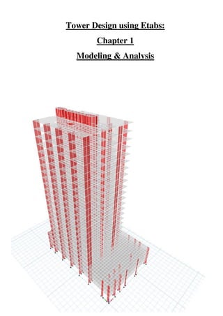
  • 1. Tower Design using Etabs: Chapter 1 Modeling & Analysis
  • 2. 1 | P a g e ABSTRACT Etabs is an abbreviation for “Extended Three- dimensional Analysis of Building Systems,” it is the main engineering integrated software that is used to analyze and design different structural elements. This report will show you how to use the commands in order to generate a structural building with respect to the Codes & regulations used in UAE and generate results for the design of buildings including high rise buildings. Written by: Eng.Nada Zarrak Checked by: Eng Ahmed Sameer Zarrak
  • 3. 2 | P a g e Table of Contents: ABSTRACT...................................................................................................................1 AutoCAD Stage: ........................................................................................................4 Etabs Stage:................................................................................................................6 Define:....................................................................................................................7 -Material Property:.............................................................................................7 -Frame Section Property: ...................................................................................8 -Slab Property: ...................................................................................................8 -Wall Property:...................................................................................................8 -Define Diaphragm: ...........................................................................................9 -Define Piers: .....................................................................................................9 -Define Spandrels*: ...........................................................................................9 -Define Load Patterns: .....................................................................................10 -Load Case: ......................................................................................................12 -Load Combination as per ACI 318-11: ..........................................................18 -Define Function:.............................................................................................23 -Define Mass source*: .....................................................................................24 -Define P-Delta*:.............................................................................................25 -Define Modal Case*:......................................................................................26 -Define Auto Construction Sequence Load Case*: .........................................27 Assign: .................................................................................................................28 Assign Joint Restraint:.....................................................................................30 Assign Piers: ....................................................................................................31 Assign Spandrels:.............................................................................................32 Assign Modifiers*:...........................................................................................32 Assign Release/Partial Fixity for Frame:.........................................................35 Run the Model: ....................................................................................................36 1- Standard Solver............................................................................................36 2- Advanced Solver..........................................................................................36 3- Multi-threaded Solver: Provide no accuracy of the computation................36
  • 4. 3 | P a g e Display the Results: .............................................................................................37 Storey Base Shear: ...........................................................................................37 Modal Mass Participation Ratio: .....................................................................41 Torsion Irregularity:.........................................................................................42 Displacement of the building against Wind Load............................................47 Story Drift against Seismic Load:....................................................................50 Seismic Story Drift Check: ..........................................................................51 Wind Story Drift Check:..............................................................................52 Solving the Errors in Response Spectrum: ..........................................................54 General Notes: .....................................................................................................55 Errors in Etabs: ....................................................................................................56 Resolve instabilities:............................................................................................58 Definitions: ..........................................................................................................59 1. Slab Modeling Type:...............................................................................59 2. Wall Property Type:................................................................................59 3. Diaphragm Rigidity: ...............................................................................59 4. Property Modifiers:.................................................................................60 5. Spandrels:................................................................................................60 6. Seismic Load Pattern: .............................................................................61 7. Wind Load Pattern:.................................................................................63 Explanation about Wind Load Calculation in ASCE 7-10:.........................65 8. Spectrum Case: .......................................................................................67 9. Mass Source:............................................................................................68 10. P-Delta: .................................................................................................69 11. Modal Case: ..........................................................................................70 12. Auto Construction Sequence Load Case: .............................................71 Conclusion: ..................................................................................................................72 Special Thanks:............................................................................................................73
  • 5. 4 | P a g e AutoCAD Stage: 1- Prepare your AutoCAD file in layers in order to ease the stage of drawings. A- Divide your layers according to your structural elements  Slab (mesh as ploy line) To mesh the slab you either can draw them in AutoCAD or use any kind of software such as Robot or Saap. "Note that the size of mesh to be used shouldn't be less than 2 as our main use of Etabs isn't about Slab analysis rather than only transferring the load and reactions, so decreasing mesh size will slow the analysis procedure and will have no use for our Design. One important note that the mesh should have min of 3& max of 4 legs, 5 sided shapes cause errors in the analysis." Figure 1: AutoCAD dwg, Slab mesh using Robot Software
  • 6. 5 | P a g e  Beam (as line) "Note that when drawing lines of beam it should be connected to the center of the column, at the edge of the wall & its length divided with the mesh".  Column (dot / represent its center)  Wall (line) "Note that the lines of wall and beams and the point of columns should be connected to the slab mesh in order to have no warning on Etabs. Make sure that you divide the wall according the division of the mesh so a realistic structure is represented." B- Save the AutoCAD file as DXF and check if the drawing is in "Meters." "Note that you arrange your floors in such away similar floors are represented in one dxf file and later on it will be replicated on Etabs." Figure 2: AutoCAD dwg, Beam connected to Slab mesh 7 edge of the wall
  • 7. 6 | P a g e Etabs Stage: 1- Open Etabs --> file-->new model-->use Built-in setting with "Metric" & choose the Concrete Design code "ACI 318-11"-->ok. For example or other Codes 2- Use the blank page --> custom story data: use elevation as given in the AutoCAD plan--> and No Grid Spacing is needed. Figure 3: Etabs2015 Model Initialization Figure 4: Etabs2015 New Model Quick Templates
  • 8. 7 | P a g e 3- File--> Import -->DXF/DWG FILE OF ARCHITECTURAL PLAN --> unit: m, factor:1 4- You can custom the stories going to Edit--> Edit stories and Grid System 5- Once your Main input is ready you can start Defining your element. Define: -Material Property: Weight per Unit Volume = 25 KN/m3 for reinforced concrete Modulus of Elasticity= 4700√𝑓′𝑐, f'c=0.8fcu Design property data-->Modify-->Specified concrete Compressive Strength f'c = 48 MPA if fcu = 60 MPA for example. Figure 5: Etabs 2015 Material Property Data
  • 9. 8 | P a g e -Frame Section Property: Columns: "Note that you don't have to define the frame element as later on while drawing it will be defined by itself. However you only have to make sure that the "ConcCol" Material is same what you have defined in the 1st step." Beams: "Note you have to define your beams element unlike columns. So name your beams and set the material property same as what you have defined." For this step you don't have o assign the framing Modifier property as later on we will explain the use of the property and how to assign then in professional way -Slab Property: Material = as what you have defined previously Modeling type = Shell-thin * Property Data Type = Slab Thickness=26cm according to the usage of the slab for example. -Wall Property: Property Type= Specified* Wall Material = what you have defined Modeling Type= Shell-Thin Thickness = according to your AutoCAD plan or the assumption.
  • 10. 9 | P a g e -Define Diaphragm: Diaphragm name= D1 Rigidity = Semi Rigid* -Define Piers: Add piers name according to the division of the wall in your structure. This step can't be done unless the division of the wall has been drawn. Later on it will be shown in the explanation below. -Define Spandrels*: Add Spandrels name according to the number of walls excited. This step can't be done unless the division of the wall has been drawn. Later on it will be shown in the explanation below. Figure 6: Etabs2015 Diaphragm Data Semi Rigid
  • 11. 10 | P a g e -Define Load Patterns: a- Dead: which represent the own weight of the elements with self multiplier= 1 which is mean that the program assign it by itself. b- Live load: depends on the usage of the structure, you can refer to BS code, ACI code or Authority Regulation. For residential use LL=2kn/m2. c- Finish= super dead d- Stair line load = other e- Temperature = Temp (used when the width or length of the building >=50m or as per Authority Regulations. f- Seismic (lateral force) * "ex" &"ey" = seismic, according to the authority -- > UBC97 is used --> Modify Lateral Load:
  • 12. 11 | P a g e "Note that we only need to define the static dynamic load for the reason of equalizing the base shear value that later on will be explained." g- Wind* = type: wind --> Code: ASCE 7-10-->Modify Lateral load-->
  • 13. 12 | P a g e -Load Case: Since load pattern has been defined, Etabs automatically defines the load case type of the patterns as linear static, However additional Load Case will be added for the P-delta Analysis of the structure and later on its result will be compared with the static seismic load, it is called Spectrum*. "Note you have first to define "Function" before you add the load case, you can check this step as shown in the Define section below in this report" Four cases will be defined two in different direction but with a Diaphragm Eccentricity = 0 and the other two with Diaphragm Eccentricity = 5% CASE 1: Spec-x - Load Case type: Response Spectrum - Load type: Acceleration - Load name: U1(x-direction) & U3 (z-direction), added to count for UZ for the Modal Mass Participation ratio. - Function: "as you have defined" Figure 7: Load Patterns
  • 14. 13 | P a g e - U1 Scale Factor: = g*I/R, {g = ground acceleration, I=importance factor, R=reduction factor, same value used for static seismic load define} = 9.81*1/5.5 - U3 Scale Factor = (2/3)*U1 scale factor. "Note that you can apply any value of scale factor because later on it will be changed when compared with the static dynamic load you can have a scale factor =1000 for example." - Diaphragm Eccentricity: 0 CASE 2: Spec-y: same procedure is done however with load name = U2 CASE 3: Spec-x-1 - Load Case type: Response Spectrum - Load type: Acceleration - Load name: U1 & U3 - Function: "as you have defined" - U1 Scale Factor: = g*I/R, {g = ground acceleration, I=importance factor, R=reduction factor} = 9.81*1/5.5 - U3 Scale Factor = (2/3)*U1 scale factor. - Diaphragm Eccentricity: 5% or 0.05. CASE 4: Spec-y-1: same procedure is done however with load name = U2 and Diaphragm Eccentricity = 5% or 0.05. "Note that Load Case Spec-xy is used in case the structure shape was irregular."
  • 15. 14 | P a g e Figure 8: Load Case 1, Spec x
  • 16. 15 | P a g e Figure 9: Load Case 2, Spec y
  • 17. 16 | P a g e Figure 10: Load Case 3, Spec x-1
  • 18. 17 | P a g e Figure 11: Load Case 4, Spec y-1
  • 19. 18 | P a g e -Load Combination as per ACI 318-11: S: service load U: ultimate load DL: summation of all dead load LL: summation of all live load S1 = DL+0.75LL+0.75TEMP S2=DL+0.75LL-0.75TEMP S3=DL+WIND S4=DL+0.7 SPECx S5=DL+0.7 SPECx1 S6=DL+0.7 SPECy S7=DL+0.7 SPECy1 S8=DL+0.75 LL + 0.53 SPECx S9=DL+0.75 LL+ 0.53 SPECx1 S10=DL+0.75LL+0.53 SPECy S11=DL+0.75LL+ 0.53 SPECy1 S12=DL+0.75LL+0.75 WIND S13=DL+0.75LL-0.75 WIND S14=0.6DL+WIND S15=0.6DL-WIND S16=0.6DL+0.7 SPECx S17=0.6DL+0.7 SPECx1 S18=0.6DL+0.7 SPECy S19=0.6DL+0.7 SPECy1 S20=DL S21=DL+LL S22=DL+LL+TEMP S23=DL+LL-TEMP ENVELOPE SERVICE= all Service load Load combination type: Envelope
  • 20. 19 | P a g e ------------------------------------------------------------- U1=1.2DL+1.6LL+1.2TEMP U2=1.2DL+1.6LL-1.2TEMP U3=1.2DL+1.6LL+0.8WIND U4=1.2DL+1.6LL-0.8WIND U5=1.2DL+LL+1.6WIND U6=1.2DL+LL-1.6WIND U7=1.4DL U8=0.9DL+1.6WIND U9=0.9DL-1.6WIND U10=1.2DL+LL+SPECx U11=1.2DL+LL+SPECx1 U12=1.2DL+LL+SPECy U13=1.2DL+LL+SPECy1 U14=0.9DL+SPECx U15=0.9DL+SPECx1 U16=0.9DL+SPECy U17=0.9DL+SPECy1 ENVELOPE ULTIMATE= all Ultimate load Load combination type: Envelope ENVELOPE ULTIMATE (SPECx) = all Ultimate load for SPECx Load combination type: Envelope ENVELOPE ULTIMATE (SPECy) = all Ultimate load for SPECy Load combination type: Envelope "Note that Two Envelope Combos were added for both direction of SPEC in order to check the Drift accordingly."
  • 21. 20 | P a g e "Note: another Model will be represented for Wind drift Checking: Load Combination": Wind Drift = DL+0.5LL+0.7 WIND --> X direction = DL+0.5LL-0.7 WIND --> Y direction This model will have no release for the column and according to UBC 97 you will multiply modifier 0.7(for column) by 1.43 =1 Figure 12: ASCE 7-10, Commentary Appendix C
  • 22. 21 | P a g e Once you have finished this step it is important to Check the model in case any overlapping in the mesh appears -> Go to Analyze-->Check model --> Length Tolerance of check = 0.00001 or you can increase the length for more accurate checking. Don't forget to choose all the selections. Figure 13: Check Model command
  • 23. 22 | P a g e P-Delta Analysis: As shown in the figure the name p delta is driven out by the effect of P (Normal force, the force generated at the top and bottom of the column) * delta (horizontal displacement) and the result is the Moment which will cause a lateral deflection. The effect of P delta is severe in case of resisting moment frame system in high rise building when an earthquake is applied. P delta generates additional shear force and bending moment in columns so the structure should be sufficient to shear resistance in addition to the earthquake shear otherwise the building may fall down. To start defining P delta analysis:
  • 24. 23 | P a g e -Define Function: Response Spectrum --> add new function "make sure function type is according to the code used" -->seismic coefficient, Ca =0.24 -->seismic coefficient, Cv =0.32 Those coefficients are driven from the static Seismic load definition in the previous step. -->ok Figure 14: Function parameter
  • 25. 24 | P a g e -Define Mass source*: Add mass source name--> modify--> Figure 15: Mass Source Parameter
  • 26. 25 | P a g e -Define P-Delta*: Iterative-Based on loads--> Dead loads = 1.2, Live Loads=0.5 Figure 16: P-Delta Load Combination
  • 27. 26 | P a g e -Define Modal Case*: Figure 17: Modal Case parameter
  • 28. 27 | P a g e -Define Auto Construction Sequence Load Case*: Figure 18: Auto Construction Sequence Case
  • 29. 28 | P a g e Assign: 6- Once you have finished the Define bar you can start drawing using the Assign menu: This step is the most important step for the Output of the Design. -Note that arranging the layers in AutoCAD will now help you to draw the element easily on Etabs2015. Start by the Slab element --> at the left bar choose Draw floor -->choose the property defined previously-->in the left bar: Model Explorer -- > Display --> View -> Architectural plan -->Layer Slab--> right click -- >Assign Area. You will notice that the mesh element has been drawn easily with the slab property chosen. "Note that you have to understand that the slab was already divided in a mesh with size 2 as done in the previous step which means that we have to remove the default of the Etabs2015 for the slab mesh as if that step didn't go correctly it will consume time for the finite element analysis as the Etabs will re-divide our manual mesh into smaller mesh --> an important step has to be done before continue drawing other elements. Go to Select all --> Assign --> Slab Automatic Mesh --> None." -The Same procedure is done for Column and Beams. However for wall element I prefer to draw them manually. Make sure the Snap option is on so when drawing wall element it will be connected with the slab node. -Since beams were drawn from center to center of columns-->don't mind that the position of the beam isn’t at the right location because in Etabs it will be moved to its original position using “insertion point”. First make sure that the beams are intersecting properly. "Note: if two beams intersect and to make sure that they meet at a point-- >select the two beams-->edit-->divide frame --> now to make sure that they are intersected three beams should appear."
  • 30. 29 | P a g e Insertion point is used to reposition the beam to its original location while it's still drawn from center to center of column this step is done for showing the result with the eccentricity of the beam. Select the beam. Right click  go to design in the same window open insertion point  and see where you want to move the beam at which edge I: x or I: y, you can see how much to move in AutoCAD that will move the beam the place you have in AutoCAD however it is still defined in the center of the column  to show how they moved “Extrude Frame”. 7- The next important step is to start dividing the Shear wall using elevation as it will represent the mesh of wall Start naming the elevation according to your plan. To start drawing go to Draw --> Draw Developed elevation-->name it-->ok Then using the arrow, draw at the center of the wall starting from a point and ending with a point "make sure you draw the line with the center of wall in order to appear in the elevation plan." Now the Elevation will show you the cross section of the wall --> for each floor you will select and divide in such a way all the points meet at the same line so in errors appear. This Step is considered somehow a long one as you have to divide the walls in such a way the length of the door is then to be removed from the wall section. Using move joint command could be helpful. "Note that the default of the wall mesh is none so it means our own division of the wall is the mesh not like what we have done previously with the slab mesh." Since all your structural elements are drawn, it is time to start assigning the main factors for your design analysis.
  • 31. 30 | P a g e Assign Joint Restraint: Since we are using piles as a foundation, joint will have a fixed support assignment. Go to plan-->Base-->select all the joint --> go to Assign-->Joint -->Restraint-->Fixed (1st select from the left side) Figure 19: Joint Restraint
  • 32. 31 | P a g e Assign Piers: Assigning piers is very important for the wall design. Walls at the same alignment in different floors should have the same pier name. Go to Select--> select according to your appropriate type of selection-- >Assign-->Frame-->Pier name
  • 33. 32 | P a g e Assign Spandrels: Spandrels are assigned to the walls above the doors in the shear wall. Go to Select--> select according to your appropriate type of selection-- >Assign-->Frame-->Spandrel name Assign Modifiers*: According to ACI 318-11, chapter 10, each structural element has a property Modifier: Figure 20: Property Modifiers according to ACI 318-11
  • 34. 33 | P a g e To Assign Stiffness Modifiers: Select (Slab) for example -->Assign  shell  Section modifiers. (f11=f22=f12=m11=m22=m12) = 0.25 for flat slab and 0.5 for PT slab.
  • 35. 34 | P a g e For Frame (Column) -->Assign-->Frame-->Property Modifier=0.7 For Frame (Beam) -->Assign-->Frame-->Property Modifier=0.35
  • 36. 35 | P a g e Assign Release/Partial Fixity for Frame: According to the Municipality both ends of the column need to be released which means that the column will not be designed to handle the Seismic Forces. Go to  Select-->selectobject type Column. Go to Assign-->Frame-Release/Partial Fixity  Release Moment by selecting the options for start point & end point Figure 21: Moment Release for Frame
  • 37. 36 | P a g e Run the Model: Go to Analyze--> Advanced SAPfire option --> There are three Solving Method Options: 1- Standard Solver: this option is very useful for cases where model fails under p-delta analysis. Using this option will show you the nodes that are free or not connected to the mesh or wall. Such warnings will cause instabilities in the structure and thus fails in p delta. 2- Advanced Solver: this is the program default solver option however it doesn't show the lost of digits or free nodes. 3- Multi-threaded Solver: Provide no accuracy of the computation "Note: Always start with the standard solver so you can fix the nodes that didn't show in the check model."
  • 38. 37 | P a g e The Main analysis results to be checked are: a. Storey Base Shear b. Modal Mass Participation Ratio c. Torsion Irregularity d. Displacement & Story Drift “Note that the run should not take a long time otherwise it means that there is an error in the modeling which is taking time for Etabs to solve.” Display the Results: Story Base Shear: It is the total Lateral Force or shear at the base.
  • 39. 38 | P a g e Once you have run the analysis, go to  Display  story Response plots  Display type: Story Shear “Note before you choose the Case/Combo you have to make sure that Modal case appears so it means that the p delta analysis has been generated”  Case/combo: EQx Read the value: Snapped to: and write it down, Do the same procedure for Case/Combo: SPECx Now These two values have to be same, if they aren’t then you have to divide the Static load (EQx) over the Dynamic load (SPECx) to find the ratio that need to be multiplied to the Scale Factor that was added. Go to Define  Load Case  Spec x  Modify  Scale factor: Multiply the Ratio ( 𝑥 𝑥 )with the value written previously (U1&Uz) Rerun the Analysis "Note that you have to do the same thing for SPECy and EQy."
  • 40. 39 | P a g e
  • 41. 40 | P a g e
  • 42. 41 | P a g e Modal Mass Participation Ratio: Go to Display --> Table --> Analysis --> Results --> Modal Results --> Modal Mass Participation Ratios. Go to the last Mode number --> Sum Ux, Sum Uy & Uz = 90% or more according to ASCE 7-10, Section 12.9.1 "Note that in Case Sum of Ux,Uy and Uz is less than 90% you have to increase number of Modes, However note that increasing to many numbers of mode may indicates that there is an error in the structure. Try to Check the Model in case there is any error in the mesh, or the Diaphragm is not assigned to all mesh elements." Figure 22: Modal Mass Particiption ratio as per ASCE 7-10, Section 12.9.1
  • 43. 42 | P a g e Torsion Irregularity: Since we are studying the structure due to earthquake load, it is important to check the modal against torsional behavior during an earthquake. It is a result of eccentricity of seismic forces. Torsional Irregularity mainly exists if structural building undergoes earthquake and wind force (horizontal forces) which means that the building should be checked if any torsional irregularity appears. According to ASCE 7-10 & UBC 97, torsional irregularity appears when maximum story drift over average story drift is more than 1.2 {( 𝑚𝑎𝑥 𝑎𝑣𝑔 ) > 1.2}. Figure 23: Torsion Irregularity as per ASCE7-10, Section 12.8
  • 44. 43 | P a g e Figure 24: Torsional Amplification Factor as per ASCE 7-10, Section 12.8 Figure 25: Torsional irregularity as per UBC 97, Table 16-M
  • 45. 44 | P a g e To check if the Ratio is more than 1.2 or less, Go to Display --> Show Table -- > Results --> Displacement--> Diaphragm Max/ Avg Drifts --> Choose load Case Spec x or y --> check the Ratio For Cases where the Ratio is more than 1.2 and less than1.4--> Torsional Irregularity should be solved: 1- Prepare an Excel sheet where you have to insert these values according to the floors with the torsional irregularity: U max: to get the value --> go to Display --> Deformed Shape --> Case: Spec x --> check the value at the left or right side of the floor and get the maximum value.
  • 46. 45 | P a g e U min: will be the lower value of the left or right side of the floor Uavg = (Umax+Umin)/2 Umax/Umin = get the value from the table = Ratio or calculate it using Excel EccNewRatio = 𝑎𝑡𝑖𝑜 . ∗ 0.05 EccNew (m) = in Etabs the new value of eccentricity will be added in meters, to get the value --> for X direction you will multiply the New Ratio will the vertical dimension of the floor. As shown in the figure, the black line represents the vertical dimension of the floor according to the direction of the displacement.
  • 47. 46 | P a g e To insert the new value of Eccentricity: 1- Go to Define --> Load Case --> Spec x o y according to what direction you choose to start with. 2- Diaphragm Eccentricity --> Modify/Show --> 3- Add the Stories that require the new Eccentricity as shown in the figure above. 4- Note that same procedure should be done for the other direction.
  • 48. 47 | P a g e Displacement of the building against Wind Load Open the Model of wind drift in order to check lateral deflection of the building. Both Direction of wind load will be compared with the Max allowable lateral deflection. Go to Display --> Deformed shape --> Figure 26: Etabs2015 Deformed Shape, Wind Drift X
  • 49. 48 | P a g e Go to Last floor and make sure Joint is enabled from visible object --> Check Node from up and down of the floor (Ux)
  • 50. 49 | P a g e The two figures show the Ux at up end and left end --> taking max value of Ux and compare it with (L/500) as per ASCE 7-10, CC.1.2. (L/500) is the value used in general. Same procedure will be done for the other Direction. Figure 27: ASCE 7-10, CC.1.2 Drift of Walls and Frames
  • 51. 50 | P a g e Story Drift against Seismic Load: It is the Lateral Displacement of one level relative to the other level above or below. Note that Drift due to Seismic and Wind should be checked in separate models. Determine of Drift depends on the load combination and period of recurrence. Since seismic force is already factored, factor is always 1 in the load combination of ASCE. The recurrence period of seismic force is 50 years. However for wind drift, 50 years wind is converted to 10 years service wind force as recommended by ASCE cc.1.2. Note that the UBC 97, Section 1630.10 Story Drift Limitation says that if the period of the structure (T) was less than 0.7 second then the maximum story drift shall not exceed 0.025*story height. While if the period (T) was more than 0.7 then a limit of0.02*story height is used. Figure 28: UBC 97, Section 1630.10 Story Drift Limitation
  • 52. 51 | P a g e To check from Etabs the period of the structure: Go to Display--> Show Table-->Results--> Modal Results --> Modal Periods and Frequencies: From Figure above Mode 1 shows a period of 2.994>0.7 second --> 002*story height is used. Drift will be checked against the two Lateral loads (Wind & Seismic) Seismic Story Drift Check: Starting with the Seismic Story Drift Check, an Envelope Load combination of SPECx and SPECy was made from the previous steps. This Load Combination will help in finding the worst case of the Spectrum to check for story drift. To check Story Drift from Etabs: Go to--> Display--> Show Table --> Results-->Displacement--> Story Drift--> choose load combo "Envelope SPECx" --> Choose Direction X The Table will show the Ratio of Drift which you will compare it with the Allowable Story Drift Ratio (0.02) as per ASCE 7-10, Table 12.12-1. Note that our Risk Category is ІІ as per ASCE 7-10, Table 1.5-1. "Note that Etabs show the Ratio which represent (Point value at story x - Point value at story below or above for the same point). If this ratio was multiplied by the story height it will give the value which you will compare it with 0.02*h." The same check should be done for the Y direction. Figure 29: Etabs 2015, Modal Periods and Frequencies, Mode1
  • 53. 52 | P a g e Wind Story Drift Check: Open the model you named previously as Wind drift and recheck the wind drift Load combination from Section Load Combination in the previous steps. To check Story Drift from Etabs: Go to--> Display--> Show Table --> Results-->Displacement--> Story Drift--> choose load combo "wind drift x" --> Choose Direction X Figure 31: Etabs 2015, Story Drift checking by Wind Drift in X direction Figure 30: Etabs2015, Story Drift Checking by Ultimate Envelope Spec X
  • 54. 53 | P a g e Figure 32: Allowable storey drift as per ASCE 7-10, Section 12.12 Figure 33: ASCE 7-10, Chapter 1, Table 1.5-1 Risk Category
  • 55. 54 | P a g e "Note that if there are stories showing excessive values of story drift, it is because the node or point at that location is not connected to the slab mesh or column. Modeling technique should be drawn well otherwise it will cause unrealistic values of drift and in other results". Solving the Errors in Response Spectrum: 1- When you run the analysis go to last run analysis in order to show how many Eigen value below the shift this indicates that the structure is instable 2- Increase first the section of the walls or columns. 3- Make sure that there is no additional story, for example if you used to have 30 stories and you want only 29 stories go to modify grids and delete that story as it affects the analysis of the spectrum. 4- In order to check that all the members are connected together and there is no element outside the mesh that could affect the stability, go to “start Animation” and see the behavior of the elements.
  • 56. 55 | P a g e General Notes: 1- Should twin tower be modeled separately in Etabs? The answer is yes because the twin towers are separated by an expansion joints at the podium level  there is no load transfer between them + we perform dynamic analysis which requires us to have different load scale factors for each tower. 2- In case you want to rotate the model select the Model  Edit  Replicate  Radial  Choose the angel of rotation. 3- In case the objects weren’t shown it means you have to go  View  show all object. And make sure that in the option all the layers are ticked. 4- Note in case load case Spec didn’t show in the story response plot after running  Reassign the Diaphragm and recheck the mesh as it is the main reason of the instability make sure that no mesh is assigned to the slab as we already draw them meshed. 5- In case you import a drawing and when you want to draw it doesn’t snap  draw  snap option  Select all  apply. 6- Note if you want the modal to run for a specific load case  Analysis  Set load case to run  and choose whatever load cases you want to run for.
  • 57. 56 | P a g e Errors in Etabs: 1- Beams “are too close” it means you have to: a- Draw in AutoCAD from center to center of column b- In case beams intersecting  draw them in AutoCAD in such a way the “green rectangular sign appears” when drawing from line to line that means they are drawn connected. c- Try to find the geometry in Etabs of the two beams that there y or are the same d- Or use the Move command from the Edit menu e- Another way is that you select the two beams and then Edit--> Edit frame--> Divide frame --> If the two beams became three beams it means that the beams are now connected at one point. 2- Slabs are too close, you have to read in which floors, note that in case you have different slabs in one floor, overlapping could happens  you have to read the joint label and check the geometry in such a way slabs wont overlap.
  • 58. 57 | P a g e 3- If there was an error saying with beam and joint then try to either move the joint to the beam or vice versa using also the copy from geometry of the point or the beam or paste it in the other geometry. 4- If you run the model and P delta analysis didn't solve --> it means that there's Instability in the structure --> Run the Model for Standard solver option--> Check the nodes given in the detail & write their location --> usually these nodes are connected to the mesh--> try to redraw the mesh or move the node to the mesh. 5- If running the Model takes a long time make sure that you have assigned "No Auto mesh" for slab as they are already meshed manually. 6- Make sure that you have defined a mass source as it affects the p delta analysis.
  • 59. 58 | P a g e Resolve instabilities: a. Run log – After analysis, ensure that the model is stable by checking the analysis log, available through File > Last Analysis Run Log. b. Dead load – Review the animation of deformed configuration under self-weight to ensure reasonable response from gravity loading. c. Mode shapes – Run modal analysis to verify that each mode-shape period is reasonable. Especially long periods will indicate instability. Animate the deformed shape of an unstable mode to identify the location of instability, then edit the model to resolve convergence problems. d. Restraints and constraints – Do not restrain DOF that are associated with a constraint. e. Release only one end – Ensure that releases are not assigned to both ends of frame objects. Releasing both ends may prevent load transfer, leading to numerical problems. Information on numerical problems is available using the Standard Solver, available through Analyze > Set Analysis Options > Solver Options. f. Avoid full fixity and full rigidity – Rather than applying full fixity to DOF and full rigidity to structural objects, restrained and rigid conditions should be modeled using sufficiently large stiffness values, perhaps on the order of 1e11, or 1e3 to 1e4 times the stiffness of nearby members. Stiffness values may be assigned using spring constants, property modifiers, or section properties. Full fixity or full rigidity may cause numerical sensitivity in linear solutions and singularities in nonlinear numerical formulation, leading to convergence problems or instabilities. Reference: https://wiki.csiamerica.com/display/kb/Troubleshooting+Checklist
  • 60. 59 | P a g e Definitions: 1. Slab Modeling Type: Membrane: used to represent in plane stiffness of members which means that is it has no bending resistance Shell: they have in plane and out plane stiffness thus they are more realistic for any structural slab. Note that in Shell type we have thin and thick shell it is important to differentiate between them usually thick slab used for raft foundation while in our case of the tower design we will end up using thin-shell. If you want to know more about the difference you can read the book "Theory and analysis of elastic plats and shell- J.N.Reddy" One important note about the difference between membrane and shell is that membrane transfer 100&% of the forces to beam and doesn't take any part of load bearing thus representing slab as shell will act both as load bearing and transferring load to the support. 2. Wall Property Type: We have both Specified and Auto Select List, when the Auto Select List is used the program then will use the thinnest wall property to satisfy both the strength requirements and the lateral drift thus in our Design we have to use Specified so we can specify the wall property. 3. Diaphragm Rigidity: The importance of assigning Diaphragm is mainly to distribute the seismic forces as it connects all individual members into seismic force Resisting System. This means that we connect all the elements in order for the structure to act as one mass. Rigid: it means it's infinitely rigid which doesn't deform & it distributes forces based on connecting member’s stiffness. It is used in case we have thick slab and lateral deformation is negligible Semi-Rigid: it distributes the loads based on the tributary area of the supports. It is used in case lateral deformation is significant just like towers
  • 61. 60 | P a g e No diaphragm or Flexible diaphragm: means there's no diaphragm used to distributes the lateral forces it's also called flexible as it allows the frame to deflect independently of other connecting member 4. Property Modifiers: Stiffness Modifiers are factor used to decrease or increase property of the cross section. They are used to represent the behavior of the structure in cracked stage "Cracking of the RCC sections." According to ACI 318 if P-delta analysis is used it is important to use the cracked section for the deformation calculation and strength of the section. 5. Spandrels: This photo here shows how spandrel is being assigned. Note that walls at the same alignment have same spandrel names. Spandrels usually marked for the bracing between walls above the doors. Figure34:https://wiki.csiamerica.com/display/etabs/Pier+and+Spandrel+Labeling+and+Design
  • 62. 61 | P a g e 6. Seismic Load Pattern: -Direction & Eccentricity: you only need to select X-Dir as for dynamic analysis the only purpose of defining Static load of earthquake is to equalize it with the base shear as shown in the previous steps. -Time period Ct (ft): Program Calc = 0.02 -Importance Factor, I: According to UBC 97, Table 16-K, I = 1 -Over Strength Factor, Ductility factor or Force Reduction Factor, R: this factor is very important as it represent how much the reduction of the force will happen according to the usage and importance of the structure. In case we have Hospitals, R=1 however this means it will cost more as the structure will be designed to face almost no cracking after an Earthquake such buildings are called “Essential Buildings” or “Special”. R= Elastic/Inelastic According to UBC 97-Table 16-N-Structural System, Concrete Shear Wall, R=5.5 Figure 35: UBC 97, Table 16-N, Structural Systems
  • 63. 62 | P a g e -Damping Eccentricity = 5%: According to UBC 97 damping eccentricity of 5% is used for the uncertainty of the design and construction. It means that at Site sizes of columns or beams are not 100% exact as per design. It is considered for Safety issues however in our dynamic analysis it doesn’t matter as we are not designing our tower due to static load. -Soil Type Profile: SC -Seismic Zone Factor = 0.2 Figure 37: UBC 97, Table 16-1 Seismic Zone factor Z Figure 36: UBC97, Table 16-j, Soil Profile Types
  • 64. 63 | P a g e 7. Wind Load Pattern: -Exposure and Pressure Coefficients: choose "Diaphragms." This option allows the same wind load to be applied each time the load case is assigned. -Wind Pressure Coefficients: Program Determined - Wind Exposure Parameters: Create all sets (it will consider the four load cases as mentioned in ASCE 7-10, figure 27.4-8. E1 ratio= 0.15 E2 ratio= 0.15, According to ASCE 7-10, Figure 27.4-8 Figure 38: ASCE 7-10, Figure 27.4-8, Design Wind Load Cases
  • 65. 64 | P a g e - Wind Speed (mph) =101 as per ASCE7-10 maps -Exposure Type: B -Gust Factor: usually a value of 0.85 is assigned however it is important to assign the value required according to the frequency of the structure. 1- Save the model and name it for "Wind Drift" 2- Assign a frame modifier = 1, and don't Release Fixity of Frames. 3- Run the Model 4- Display period of the structure, Display --> Show Table --> Results--> Model Result--> Modal Periods and Frequencies 5- The table will show the number of modes added with the period in sec, however the first two modes are always the ones with the larger values. Mode 1 represents the period in X direction and Mode 2 represents the period in Y direction. 6- Using Excel sheet, insert the value of T1 or T2 and take the worst value of the Gust Factor. "Note that value greater or near to 1are considered a worst case"
  • 66. 65 | P a g e Explanation about Wind Load Calculation in ASCE 7-10: - Chapter 27 talks about wind load calculation - Chapter 26 talks about general requirements There are three methods for wind force calculation: METHOD 1: Envelope Procedure MWFRS, C&C (Simplified Method 2 Low-Rise) MWFRS: Main Wind Force Resisting System METHOD 2: 1- All-Heights: Directional Procedure MWFRS, C&C 2- Low Rise: Envelope Procedure MWFRS, C&C METHOD 3: Wind Tunnel Procedure ---------------------------------------------------------------------- - SECTION 26.1.2 talks about permitted procedure -Section 26.1.2.1 talks about Directional & Envelope Procedure MWFRS -Section 26.2 explains Definitions -Section 26.3 explains Symbols -Section 26.4 shows Sign Convention + (force toward surface) - (away from surface) -Section 26.5 shows wind Speed maps (depends on Risk Category) We have 4 risk categories For Risk 1  table 1.5-1 page 2 For Risk 2  page 247a, 247b USUALLY RESIDENTIAL BUILDINGD HAVE RISK CATEGORY 2 -Section 26.7 talks about Exposure type
  • 67. 66 | P a g e -Section 26.7.2 talks about surface roughness B (urban or woods), C, D (flat and wide) such as if you live in cost or desert or shore line -Section 26.8 shows topography effects, wind speed up over hills, ridges etc. K1, K2, K3  figure 26.8 -1 And if there is no hills  kzt = 1.0 -Wind gust  if building is rigid, gust effect factor will decrease load 0.85 Building rigidity depends on natural frequency of the building (Usually all low rise building are considered rigid) A low rise building: 1- Height less than 60 ft. 2- Height must be less than either of width or length of the base -Section 26.10 talk about Enclosure (means hole or opening in the building) 1- Enclosed 2- Partially Enclosed 3- Open (at least 25% of wall is opened by glass or door) -Section 26.11 talks about Internal pressure  table 26.11-1 Gcpi: = 0 for open (- or +) 0.55 for partially open (- or +) 0.18 for enclosed Chapter 27: discusses MWFRS –directional procedure, Table 27.2-1 gives procedure for calculation p260 -Section 27.3 = velocity pressure  it converts wind speed into pressure on the building AND FROM PRESSURE we will get wind load.
  • 68. 67 | P a g e 8. Spectrum Case: Seismic Force Calculation: 1- Static Method: defining static load Ex & Ey 2-Dynamic Method, defining Modal Response Spectrum: is a method used to determine Seismic response of a structure. 5% damping is used to determine response spectrum curve. 3- Time History: gives response of the structure for a given periods and it depends on the previous data. ---------------------------------------------------------------------------------------- For our Analysis Dynamic Method is used. Response Spectrum analysis or (Multiple Model Response Spectrum analysis) is a linear dynamic statistical analysis method which measures from each mode of vibration to indicate maximum seismic response of an elastic structure. For High rise buildings it's not possible to predict seismic behavior with single mode that is why we consider multiple mode cases which is used for dynamic analysis. Figure 39: Modal Response Scale Factor per ASCE 7-10, Section 12.9 Figure 40: Modal Combined Method as per ASCE 7-10,Section 12.9
  • 69. 68 | P a g e 9. Mass Source: For Earthquake weight calculation, Mass source need to be defined in order for Etabs to calculate it correctly so Mass source represent the Seismic weight that will be used for the seismic calculation. Such step is important in order for Etabs distributes the seismic load correctly. It will consider a full dead load with factor 1 and live load factor =0.25, why is that? During an Earthquake dead is left the same which means that we will consider the whole weight of dead  factor =1, however for residential building the only live load left is for example furniture and that's why 0.25 of live load is considered for weight calculation. -Element self-mass: Etabs automatically add the mass of the structure by this selection, if element self-mass was checked, don’t add Dead load in the Specified load Patterns. -Additional Mass: used to account for partitions, cladding and so on. However finish load will be added in the Specified Load Patterns so no need to select. -Specified Load Patterns: Only the global Z-direction loads are considered when calculating the mass. This mass is applied to each joint in the structure on a tributary area basis in all three translational directions. -Include lateral Mass: assigned translational mass in global X&Y-axis directions and rotational mass moment of inertia about the global Z-axis are considered in the analysis. -Include vertical mass: assigned translational mass in the global Z axis direction and assigned rotational mass moments of inertia about the global X and Y axes are considered in the analysis. -Lump Lateral mass at Storey level: is checked when we have a transfer slab or planter column. (You can check CSI America documents for any reference.) Figure 41: Effective Seismic weight as per ASCE 7-10, Section 12.7
  • 70. 69 | P a g e 10. P-Delta: -Iterative Based on Load Cases: loads are derived from combination based on static load cases. These load combination is called P-Delta load Combination. This method requires iteration of specified combination to determine P-Delta effect on the structure. It considers local buckling effect more significantly more than the non-iterative one. P delta load Combination = 1.2DL+0.5LL Figure 42: P delta effect definition as per ASCE 7-10, page 60
  • 71. 70 | P a g e 11. Modal Case: Modal analysis is a linear dynamic response procedure used to calculate frequency modes and showing displacement patterns of a structure. "Modes: is a combination of a deformed shape of a structure depending on the structure mass" This step is important as it makes sure than more than 90% of the structure's mass in Ux, Uy and Uz is participating under the effect of the lateral forces (Seismic Forces). -Ritz: they are sufficient for dynamic analysis involving horizontal motion. "You can learn more about the Ritz vector in the Etabs Manual." Ritz provide a better basis when used for response spectrum -Load Type: Acceleration - Maximum Number of Modes = usually equal Number of stories in our structural building. Figure 43:Modal Mass Participation Ratio as per ASCE 7- 10,Section 12.9
  • 72. 71 | P a g e 12. Auto Construction Sequence Load Case: It is used when we have a planted column or a transfer Slab--> Go to Define--> Auto construction sequence case--> Check "Case is active" --> Load applied: add only DEAD load as Live load will be applied after the Structure is complete. Deal Load factor = 1. Now Etabs will automatically generate a load case called Autoseq, you can check by going to the load case in the Define menu.
  • 73. 72 | P a g e Conclusion: Now you can Model and analyze any kind of structural element with different number of floors and shapes. Usually Seismic effect is the main concern to handle throughout the design process. It's important to study about Dynamic analysis in order to understand how the structure responds under lateral loads. Reading, searching and questioning are your primary tools to a better structural concept. Make sure that every factor, ratio, & cases is based on the Code used in your country. Never underestimate the importance of the regulations needed throughout the design procedure. And Last but not least Civil Engineering is definitely the mother of knowledge.
  • 74. 73 | P a g e Special Thanks: -Special thanks to my father who gave me support and encouragement to start this work and completing it with this final report. -Special thanks to my mother who believed that nothing is impossible. -Special thanks to my brother Rami who provided the necessary tools and software to start the Design process. -Special thanks to every Engineer who helped in the process of learning and understanding. -Special thanks to my friends Ahmed, Ruaa, Noor, Shahd, Amani, Yuser, Zain, & Rasha. -Special thanks to everyone who is willing to learn, study and help in improving the world. For any Information, Questions or Doubts please contact: Nada.Zarrak@hotmail.com