1. By: Irfanullah Mazari
Primary Current Calculation of Transformer Stability:
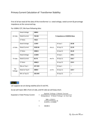
First of all we need all the data of the transformer i.e. rated voltage, rated current & percentage
impedance at the concerned tap.
For JUBAIL C27, We have following data:
HV Side
Rated Voltage 380KV
% impedance at 502MVA BaseRated Current 762.8A
CT Ratio 750/1
LV Side
Rated Voltage 115KV
HV-LV
At tap-1 20.58
Rated Current 2520.3A At tap-11 22.59
CT Ratio 3000/1 At tap-21 26.34
TV Side
Rated Voltage 13.8KV
HV-TV
At tap-1 149.1
Rated Current 83.7A At tap-11 150.7
CT Ratio 3000/1 At tap-21 153.5
Tap
Voltage
Max at Tap-1 427.5KV
LV-TV
At tap-1 ---
Rated at Tap-9 380KV At tap-11 124.7
Min at Tap-21 332.5KV At tap-21 ---
Let suppose we are doing stability b/w LV and HV,
So we will inject 380 v from LV side, and HV side we will keep short.
Expected LV Side Primary Current =
𝐴𝑝𝑝𝑙𝑖𝑒𝑑 𝑉𝑜𝑙𝑡𝑎𝑔𝑒 𝑋 𝑅𝑎𝑡𝑒𝑑 𝐶𝑢𝑟𝑟𝑒𝑛𝑡
%𝐼𝑚𝑝𝑒𝑑𝑎𝑛𝑐𝑒 𝑋 𝑅𝑎𝑡𝑒𝑑 𝑉𝑜𝑙𝑡𝑎𝑔𝑒 𝑎𝑡 𝑡ℎ𝑎𝑡 𝑡𝑎𝑝
=
380 𝑥 2520.3
0.2259 𝑥 115000
A
= 36.86 A
Tap: 11
2. By: Irfanullah Mazari
So, 36.86 current should flow through the primary of LV side, if you inject 380V across the LV side.
Expected LV side Secondary Current =36.86 x
1
3000
A
=12.2mA
For calculation of HV side Primary current, we will use
below formula,
HV Side Primary Current =
𝐿𝑉 𝑠𝑖𝑑𝑒 𝑟𝑎𝑡𝑒𝑑 𝑣𝑜𝑙𝑡𝑎𝑔𝑒 𝑋 𝐿𝑉 𝑠𝑖𝑑𝑒 𝑝𝑟𝑖𝑚𝑎𝑟𝑦 𝐶𝑢𝑟𝑟𝑒𝑛𝑡
𝐻𝑉 𝑅𝑎𝑡𝑒𝑑 𝑉𝑜𝑙𝑡𝑎𝑔𝑒
=
36.86 𝑋 115000
380,000
=
4238990
380,000
= 11.15 A
Expected HV side Secondary Current =11.15 x
1
750
A
=14.87 mA
HV
CTs
LV
CTs
HV
CB
LV
CB
Auto
Transformer
R
Y
B
TV
CB
Neu.
CT
TV
CTs
3. By: Irfanullah Mazari
Same procedure will repeat, when you are doing stability b/w LV and TV. But you have to Put
Impedance b/w LV-TV in formula. Inject from LV side and
TV side keep short. Like
Expected LV Side Primary Current =
𝐴𝑝𝑝𝑙𝑖𝑒𝑑 𝑉𝑜𝑙𝑡𝑎𝑔𝑒 𝑋 𝑅𝑎𝑡𝑒𝑑 𝐶𝑢𝑟𝑟𝑒𝑛𝑡
%𝐼𝑚𝑝𝑒𝑑𝑎𝑛𝑐𝑒 𝑋 𝑅𝑎𝑡𝑒𝑑 𝑉𝑜𝑙𝑡𝑎𝑔𝑒 𝑎𝑡 𝑡ℎ𝑎𝑡 𝑡𝑎𝑝
=
380 𝑥 2520.3
1.24 𝑥 115000
A
= 6.71 A
So, 6.71A current should flow through the primary of LV side, if you inject 380V across the LV side and
TV side keep short.
TV Side Primary Current =
𝐿𝑉 𝑠𝑖𝑑𝑒 𝑟𝑎𝑡𝑒𝑑 𝑣𝑜𝑙𝑡𝑎𝑔𝑒 𝑋 𝐿𝑉 𝑠𝑖𝑑𝑒 𝑝𝑟𝑖𝑚𝑎𝑟𝑦 𝐶𝑢𝑟𝑟𝑒𝑛𝑡
𝑇𝑉 𝑅𝑎𝑡𝑒𝑑 𝑉𝑜𝑙𝑡𝑎𝑔𝑒
=
6.71 𝑋 115000
13,800
= 55.96𝐴
So, 55.96A current should flow through the primary of TV side, if you inject 380V across the LV side and
TV side keep short.
HV
CTs
LV
CTs
HV
CB
LV
CB
Auto
Transformer
R
Y
B
TV
CB
Neu.
CT
TV
CTs
4. By: Irfanullah Mazari
But when you are doing stability b/w HV,LV and TV, than for that you have to calculate first
Impedance between these three.
So,
We have Impedance b/w HV and LV, which is 22.59 % ,
and also we have
Impedance b/w LV and TV, which is 124.57 %, so
When you are injecting voltage from LV side, than both
impedance will be in parallel.
Impedance will be = 22.59//124.7
=
22.59 𝑋 124.7
22.59+124.7
= 19.12 %
So in this case your expected LV side primary current will be
Primary Current of LV side =
𝐴𝑝𝑝𝑙𝑖𝑒𝑑 𝑉𝑜𝑙𝑡𝑎𝑔𝑒 𝑋 𝑅𝑎𝑡𝑒𝑑 𝐶𝑢𝑟𝑟𝑒𝑛𝑡
%𝐼𝑚𝑝𝑒𝑑𝑎𝑛𝑐𝑒 𝑋 𝑅𝑎𝑡𝑒𝑑 𝑉𝑜𝑙𝑡𝑎𝑔𝑒 𝑎𝑡 𝑡ℎ𝑎𝑡 𝑡𝑎𝑝
=
380 𝑥 2520.3
0.1912 𝑥 115000
A
= 43.55 A
So, 43.55A current should flow through the primary of LV side, if you inject 380V across the LV side. And
HV and TV short.
Expected LV side Secondary Current =43.55 x
1
3000
A
=14.51 mA
HV
CTs
LV
CTs
HV
CB
LV
CB
Auto
Transformer
R
Y
B
TV
CB
Neu.
CT
TV
CTs
5. By: Irfanullah Mazari
I got the following values from the calculation.
Applied Voltage 380 volts Primary Current in
(A)
Secondary Current in
(mA)Load Type Side
LV-HV-TV
HV 11.15 14.86
LV 43.55 14.50
TV 55.96 18.65
LV-HV
HV 11.15 14.86
LV 36.80 12.28
LV-TV
LV 6.71 2.23
TV 55.96 18.65
Similar calculation for other taps.