A brief look at visionOS - How to develop app on Apple's Vision Pro
003-8884-AEN.pdf
1. 003-8884-AEN, Issue 1
Corning EDGE™ Housing- 2U-XD
related literature | Search www.corning.com/opcomm. Click on “Resources/Standard Recommended Procedures.”
004-281-AEN Instruction, Sheath Removal of 1728-Fiber RocketRibbon™ Extreme-Density Cable
004-098 Instruction, Ribbon SplittingTool (RST-000)
003-291 Universal Cable Clamp (UCC-001)
001-008-AEN 2543-D-XSB Deep SpliceTray
1. General
This document describes the installation of the Corning EDGE™Housing- 2U-XD.
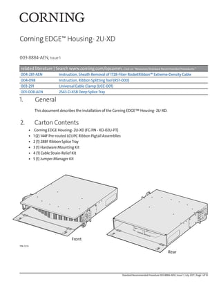
2. Carton Contents
• Corning EDGE Housing- 2U-XD (FG PN - XD-02U-PT)
• 1 (2) 144F Pre-routed LCUPC Ribbon Pigtail Assemblies
• 2 (1) 288F Ribbon SpliceTray
• 3 (1) Hardware Mounting Kit
• 4 (1) Cable Strain-Relief Kit
• 5 (1) Jumper Manager Kit
TPA-7210
Front
Rear
Standard Recommended Procedure 003-8884-AEN | Issue 1 | July 2021 | Page 1 of 10
2. Standard Recommended Procedure 003-8884-AEN | Issue 1 | July 2021 | Page 2 of 10
3. Tools and Materials Required
• Scissors (P/N 100294-01)
• Friction tape
• Needle-nose pliers
• Gloves
• Tape measure
• Utility knife with hook-blade and straight
blade
• Diagonal cutting pliers (side cutters) (P/N
100300-01)
• Screwdriver
4. Installation
TPA-6946
Step 1: Install two screws or cage nuts and screws from the hardware mounting kit.
Step 2: Place the housing in the rack by guiding the inverted U-shaped openings on the bottom of the housing
mounting brackets over the two installed screws. Start two additional mounting screws into the
mounting brackets. Tighten all screws to secure the housing to the rack.
NOTE: The mounting hardware should be installed on both sides of the rack in a location that corresponds with
where the bottom of the XD-02U-PT will be located.
TPA-7211
X2 .25 in.
3. Standard Recommended Procedure 003-8884-AEN | Issue 1 | July 2021 | Page 3 of 10
Step 3: Locate the cable strain-relief kit. Using the included hardware, install the strain-relief bracket and UCC
cable clamp onto the side of the housings that the cable will enter.
Step 4: Refer to SRP 004-281-AEN sheath removal procedure to remove 126 inches of cable sheath from
the cut end of the cable. Remove the sheath to this length in accordance to the diagram below.
TPA-7212
Cable jacket
126 in.
TPA-6950
4. Standard Recommended Procedure 003-8884-AEN | Issue 1 | July 2021 | Page 4 of 10
Step 5: With reference to SRP 004-281-AEN universal cable clamp, install and secure the prepared cable into the
appropriate UCC cable clamp installed during step 3.
Step 6: Pass the subunits through the brush-cable entry port located on the side of the housing. Although the
RocketRibbon™ cable subunit offers protection for the ribbons inside, the installer may choose to further
protect the subunits using off-the-shelf spiral wrap.
TPA-7213
Pry shims
apart here.
TPA-2953
2
1
TPA-7214
Spiral wrap
5. Standard Recommended Procedure 003-8884-AEN | Issue 1 | July 2021 | Page 5 of 10
Step 7: Measure and mark 30 inches from the end of the subunits. Remove subunit jacketing at the 30 inch
mark. The prepared cable should match the diagram below.
Step 8: Locate ribbon pigtail assemblies 1A and 1B. Carefully de-route the assemblies from the rear of the
housings and place along side the appropriate ribbon cable subunit according to your splicing plan.
The ribbon pigtail assemblies may be fastened to the ribbon cable subunits using hook-and-loop
straps along the length for ease of management.
Cable jacket Subunit Ribbon
96 in. 30 in.
126 in.
TPA-6953
1B
1A
TPA-6947
6. Standard Recommended Procedure 003-8884-AEN | Issue 1 | July 2021 | Page 6 of 10
Step 9: Carefully cut the ribbon pigtail assemblies to match the length of the ribbon fibers in each ribbon
cable subunit. Use scissors to carefully remove 30 inches of the braided mesh tubing from each
ribbon pigtail assembly so that the exposed ribbon fiber matches that of the ribbon cable subunit.
Subunit/Braided Mesh Ribbon Fiber
30 in.
TPA-6954
1A
1B
Step 10: Prepare the splice trays for splicing by attaching each 288F ribbon cable subunit to a 288F ribbon
splice tray using the tie wraps provided. Friction tape should be used to strengthen the bond
between the subunit and the splice tray.
TPA-6955
Friction tape
Tie wraps
7. Standard Recommended Procedure 003-8884-AEN | Issue 1 | July 2021 | Page 7 of 10
Step 11: Attach the appropriate two 144F ribbon pigtail assemblies to a 288F ribbon splice tray using the tie
wraps provided. Friction tape should be used to strengthen the bond between the ribbon pigtail
assemblies and the splice tray.
Step 12: With reference to 2543-D-XSB splice tray (SRP P/N: 001-008-AEN), pre-route and trim the ribbon
fibers according to the illustration below. Begin by splicing Splice Group 1. Next add the splice insert
riser and continue splicing with Splice Group 2 until all ribbons are spliced. Complete this process
until all trays are spliced.
TPA-7215
Friction tape
Tie wraps
1
A
1
B
NOTE: With reference to SRP 004-098 Ribbon Splitting Tool, 24F ribbons
should be split into 12F ribbons using the RST-000.
TPA-6957
Splice Group 2
Add splice insert Riser
splice group 2
Splice Group 1
Group 2
288 Fiber
Subunit*
*Separate ribbons into two
144 fiber groups
8. Standard Recommended Procedure 003-8884-AEN | Issue 1 | July 2021 | Page 8 of 10
Step 13: Once all ribbons in each tray are spliced, remove the protective film from both sides of the clear splice
tray cover and place the cover onto each splice tray.
TPA-6966
1
2
3
9. Standard Recommended Procedure 003-8884-AEN | Issue 1 | July 2021 | Page 9 of 10
Step 14: Carefully coil the ribbon cable subunits and ribbon pigtail assembly bundle into the rear of the XD-
02U-PT housing in a counter-clockwise direction. Secure the splice trays into the splice tray holder
using the provided hook-and-loop straps.
TPA-7216
Hook-and-loop
strap
Top cover
transparent for interior
view
Step 15: Carefully close the rear door of the housing to ensure that the subunits and ribbon pigtail assemblies
remain clear of the door.
TPA-7217