Remote sensing and image interpretation
•Download as PPTX, PDF•
99 likes•21,753 views

Remote sensing interpretation basic

Recommended
More Related Content
What's hot
What's hot (20)
Similar to Remote sensing and image interpretation
Similar to Remote sensing and image interpretation (20)
Recently uploaded
Recently uploaded (20)
Remote sensing and image interpretation
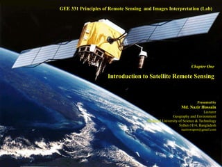
- 1. Chapter One Introduction to Satellite Remote Sensing GEE 331 Principles of Remote Sensing and Images Interpretation (Lab) Presented by Md. Nazir Hossain Lecturer Geography and Environment Shahjalal University of Science & Technology Sylhet-3114, Bangladesh nazirswapon@gmail.com
- 2. What is Remote Sensing? Remote? Sensor? A detecting instrument; a device capable of detecting and responding to physical stimuli such as movement, light, or heat Human vision is the most popular example of a remote sensing system.
- 3. Natural scene Distance Human Brain Soft copy or Hard copy
- 4. Remote Sensing In the broadest sense, remote sensing is the small or large-scale acquisition of information of an object, area or phenomenon, that is not in physical or intimate contact with the object, by the use of either recording or real-time sensing device(s) (such as by way of aircraft, spacecraft, satellite, buoy, or ship). Distance Human Brain Soft copy or Hard copyNatural scene
- 6. Stages of Remote Sensing (Cont.) Receiving and processing Sensing products Users
- 7. Stages of Remote Sensing Sources of energy Propagation of through the atmosphere Energy interaction with the surface’s features Retransmission of energy through the atmosphere Sensors: air borne/space borne Sensing product in digital/pictorial form Data interpretation and analysis Information products Users
- 8. Users
- 13. Image mosaic
- 14. Remote Sensing (Cont.) Definition of Remote Sensing Remote sensing is the science and art of obtaining information about an object, area, or phenomenon through the analysis of data acquired by a device that is not in contact with the object, area or phenomenon under investigation (Lillesand & Kiefer, 2000). Remote sensing is the science of obtaining and interpreting information from a distance using sensors that are not in physical contact with the object being observed (Randall B. Smith, 2001).
- 15. Application of Remote Sensing Mapping/Cartography Land cover & land use Agriculture: cropping pattern, diversity Forestry: forest type Environmental impact assessment: before & after Geology: rocks identification, color, luster Hydrology: drainage pattern Oceanography
- 18. Application of Remote Sensing (Cont…) Coastal monitoring Meteorology, cloud-rain, cyclone Natural hazard forecast and assessment Resource monitoring Settlement and urban planning
- 21. Satellite Imagery Satellite imagery consists of images of earth or other planets collected from artificial satellites.
- 22. Aerial photograph & Aerial photography Aerial photograph refers to the photograph taken from aircraft. Aerial photography is defined as science and art of taking photographs from the air using aerial camera. Aerial photography is the taking of photographs of ground from an elevated position.
- 23. Types of Aerial photograph Based on angular position of camera and ground 1. Vertical photograph 2. Oblique photograph
- 24. Types of Aerial photograph (cont.)
- 25. Characteristics of Aerial Photographs Synoptic view Time freezing ability Capability to stop action Availability Comparatively cheap Three dimensional perspectives Stereoscope Paris, WW2
- 26. Photogrammetry Photogrammetry is traditionally defined as the art or science of obtaining reliable measurements by means of photography (CP Lo & AKW Yeung, 2002). Photogrammetry is the science of obtaining reliable measurements of objects from their photographic image (T Eugene Avery, 1965). It deals on shape, size, geometry, scale, camera angle of aerial photos etc.
- 27. Platforms of Remote Sensing The vesicles or career for remote sensors are called the platform. Such as aircraft, satellite etc. 1. Ground base platforms 2. Air platforms 3. Space borne platforms Ground-based Airplane-based Space-based
- 28. Satellite System Sputnik 1 Explorer 1 Major types are i. Natural satellite: The Moon ii. Artificial satellite: about 65 countries have own satellite including launching capacity of 10. First satellite: Sputnik 1, launched by USSR in October 4, 1957. First American satellite: Explorer 1 (USA), 31st January 1958. Last launching countries, Turkmenistan, Laos (2015) Bangladesh: Bangabandhu 1, 1st Space Satellite, BTRC & SPARRSO, will be launched 31 Dec 2017, through 119° E long. geostationary slot.
- 29. Satellite System (Cont.) 6600 have been launched 3600 are in orbit 1000 are operational Propelling mechanism: Propelled by rocket first then use own power and finally moving through orbit
- 30. Satellite System (Cont...) Types of satellite 1. Geostationary Satellite: GMS (Japan), GOES, INTEL, TIROS 2. Polar-Orbiting Satellite: SPOT, Landsat, Geostationary Satellite Polar-Orbiting Satellite
- 31. Satellite System (Cont...) Types of satellite based on their uses 1. Communication satellite 2. Astronomical satellite 3. Navigation satellite 4. Weather satellite 5. Military satellite 6. Scientific satellite 7. Earth Observation/Resource appraisal satellite Navigation satellite Landsat 1 Landsat 8
- 32. Types of Remote Sensing Based on platform of Remote Sensing 1. Ground based Remote Sensing 2. Air based Remote Sensing 3. Space based Remote Sensing
- 33. Types of Remote Sensing (Cont…) Based on orbital characteristics 1. Geo-stationary Remote Sensing: GMS (Japan), GOES, INTEL, TIROS 2. Sun-synchronous Remote Sensing: LANDSAT, SPOT, IRS
- 34. Types of Remote Sensing (Cont…) Based on source of energy 1. Passive Remote Sensing 2. Active Remote Sensing
- 37. Types of Remote Sensing Based on component of Remote Sensing 1. Optical Remote Sensing: element- use visible, near infrared 2. Thermal Remote Sensing: element- temperature 3. Microwave Remote Sensing: element- microwave
- 38. Types of Remote Sensing (Cont.) Optical Remote Sensing: element- use visible & near infrared; only day time
- 39. Types of Remote Sensing (Cont.) Thermal Remote Sensing: element- temperature, day-night all time, temperature emission by objects up to 0oK/-273oC, mostly use in desert area
- 40. Types of Remote Sensing (Cont.) Microwave Remote Sensing: element- microwave; day & night; all places, all weather; high cost of sensing, need power to operate, ship use
- 41. Types of Remote Sensing (Cont.) Based on spectral characteristics 1. Panchromatic remote sensing: Black & White 2. Multispectral remote sensing 3. Hyper-spectral remote sensing
- 42. Types of Remote Sensing (Cont.) Multispectral remote sensing: Landsat MSS (4), Landsat TM (7), Landsat ETM+ (8), AVHRR (3)
- 43. Bands of Some Sensors Landsat MSS (1972-) o Band 1: 0.5 - 0.6 μm (visible green) 79 m o Band 2: 0.6 - 0.7 μm (visible red) 79m o Band 3: 0.7 - 0.8 μm (near IR) 79 m o Band 3: 0.8 - 1.1 μm (near IR) 79 m Landsat TM & ETM+ (1982- ) o Band 1: 0.522 -0.90 μm (panchromatic)* 15 m o Band 2: 0.45 - 0.52 μm (visible blue) 30 m o Band 3: 0.52 - 0.60 μm (visible green) 30 m o Band 4: 0.63 - 0.69 μm (visible red) 30 m o Band 5: 0.76 - 0.90 μm (near IR) 30 m o Band 6: 1.55 - 1.75 μm (mid IR) 30 m o Band 7: 10.40 - 12.50 μm (thermal IR) 120 m o Band 8: 2.08 - 2.35 μm (mid IR) 30 m
- 44. Types of Remote Sensing (Cont.) Hyper-spectral remote sensing: In this process the sensor divide spectral band into more narrow spectrum. Such as CASI contains 288 bands, AVIRIS (224), MODIS (35).
- 45. Sensor System Sensor refers to the sensing mechanism that receives the electromagnetic energy and record it. The device that receives electromagnetic radiation and converts it into a signal that can be recorded and displayed as either numeric data or image.
- 46. Classification of sensor (Cont…) SONAR Camera Based on sources of energy i. Active sensors: RADAR, SONAR, LIDAR, LASER ii. Passive sensors: various camera, scanners
- 48. Classification of sensor (Cont…) Based on number of band of the sensors i. Broad and narrow band sensor ii. Multi-spectral sensor iii. Hyper-spectral Sensor
- 49. Classification of sensor (Cont…) Based on platform/career of the sensors i. Ground based sensor ii. Air borne sensor iii. Space borne sensor
- 50. Satellite remote sensing versus Aerial photography Mechanism –highly technical vs. normal Sensors- space base vs. ground base Platforms Cost Uses & Application Efficiency Man powers
- 51. Pixel A pixel (short for “picture element”) is one of thousands of tiny spots in a grid on a display screen or printed sheet. Just as a bit is the smallest unit of information a computer can process, a pixel is the smallest element that display or print hardware and software can manipulate in creating letters, numbers, or graphics.
- 52. Image Resolution Image resolution refers to the number of pixels in an unit area of a digital photo or image. The term resolution used in both traditional and digital photography to describe the quality of the image.
- 53. Image Resolution (Cont...) Types of Resolution 1. Spatial Resolution 2. Temporal Resolution 3. Spectral Resolution 4. Radiometric Resolution
- 54. Spatial Resolution (cont.) The spatial resolution specifies the pixel size of satellite images covering the earth surface. High spatial resolution: 0.41 - 4 m Low spatial resolution: 30 - > 1000 m 1 pixel in image = 30mx30m in land 1 pixel in image = 1mx1m in land
- 55. Spatial Resolution (cont.) Below is an illustration of how the same image might appear at different pixel resolutions (practical aspect)
- 56. Spatial Resolution (cont.) 540 x 694 140 x 180 54 x 69
- 57. 40 x 40 Spatial Resolution (cont.) 320 x 320 80 x 80
- 61. Temporal Resolution The temporal resolution specifies the revisiting frequency of a satellite sensor for a specific location. High temporal resolution: < 24 hours - 3 days Medium temporal resolution: 4 - 16 days Low temporal resolution: > 16 days
- 62. Temporal Resolution Time July 1 July 12 July 23 August 3 11 days 16 days July 2 July 18 August 3
- 63. Spectral Resolution The ability of a sensor to detect small differences in wavelength It specifies the number of spectral bands in which the sensor can collect reflected radiance. High spectral resolution: 220 bands Medium spectral resolution: 3 - 15 bands Low spectral resolution: 3 bands
- 64. • Example: Black and white image - Single sensing device - Intensity is sum of intensity of all visible wavelengths Can you tell the color of the platform top? How about her sash? Spectral Resolution (Cont.) 0.4 mm 0.7 mm Black & White Images Blue + Green + Red
- 65. Spectral Resolution (Cont.) • Example: Color image - Color images need least three sensing devices, e.g., red, green, and blue; RGB Using increased spectral resolution (three sensing wavelengths) adds information In this case by “sensing” RGB can combine to get full color rendition 0.4 mm 0.7 mm Color Images Blue Green Red
- 66. Radiometric Resolution It measures of a sensor's ability to discriminate small differences in the magnitude of radiation within the ground area that corresponds to a single raster cell. The greater the bit depth (number of data bits per pixel) of the images that a sensor records, the higher its radiometric resolution. The AVHRR sensor, for example, stores 210 (1024) bits per pixel, as opposed to the 28 bits per pixel that the Landsat sensors record. Computer store everything in 0 or 1
- 68. Comparison of Satellites based on Resolution
- 69. Resolution Trade-off The trade-off may result in two different solutions: To lay emphasis upon the most important resolution, in direct dependency to the application, or To lay no emphasis on one specific resolution and at the same time the acceptance of a medium spectral, temporal and spatial resolution.
- 70. Electromagnetic Radiation (EMR) Electromagnetic Radiation (EMR) refers to the energy that moves with the velocity of light in a harmonic wave pattern and consist of both electric and magnetic field (Noam Levin, 1999). EMR is the form of energy emitted and absorbed by charged particles, which exhibits wave like behaviour and has both electric and magnetic component (Lillesand & Kiefer, 2000). Orthogonal
- 72. Properties of Electromagnetic Radiation (EMR) Fields of EMR 1. Electric filed 2. Magnetic field Wave theory of EMR 1. Velocity (V or C): 3×10⁸ m/s 2. Frequency (f) 3. Wave length (λ)
- 73. Properties of Electromagnetic Radiation (EMR) (cont..) Electromagnetic spectrum The electromagnetic spectrum is the range of all possible frequencies of electromagnetic radiation.
- 74. Properties of Electromagnetic Radiation (EMR) (cont..) Spectral bands The wavelengths are approximate; exact values depend on the particular satellite's instruments: Bands Wavelength in µm Use in Remote sensing Blue 0.44 – 0.5 Atmospheric and deep water imaging, and can reach up to 150 feet (50 m) deep in clear water Green 0.5 – 0.57 Imaging of vegetation and deep water structures, up to 90 feet (30 m) in clear water (peak vegetation reflects these wavelengths strongly) Red 0.62 – 0.7 Imaging of man-made objects, in water up to 30 feet (9 m) deep, and vegetation type Near-infrared 0.7 – 1.3 Primarily for imaging of vegetation (healthy plant tissue reflects these wavelengths strongly) Mid-infrared 1.3 – 3.0 Imaging vegetation, soil moisture content, and some forest fires Thermal infrared 3.0 – 14.0 Uses emitted radiation instead of reflected, for imaging of geological structures, thermal differences in water currents, fires, and for night studies Microwave 1mm-1m Mapping terrain and for detecting various objects
- 75. Properties of Electromagnetic Radiation (EMR) (cont..) Energy interaction in the atmosphere 1. Scattering i. Rayleigh scattering ii. Mie scattering iii. Non-selective scattering 2. Absorption 3. Transmission and refraction Interaction with the earth surface 1. Reflection: specular & defused 2. Energy interaction with earth surface feature 3. Spectral reflection of vegetation, soil and water
- 76. Interactions with the Atmosphere Before radiation used for remote sensing reaches the Earth's surface it has to travel through some distance of the Earth's atmosphere. Particles and gases in the atmosphere can affect the incoming light and radiation. These effects are caused by the mechanisms of scattering and absorption. Rayleigh scattering occurs when particles are very small compared to the wavelength of the radiation. That’s why the sky is blue. Mie scattering occurs when the particles are just about the same size as the wavelength of the radiation. Nonselective scattering occurs when the particles are much larger than the wavelength of the radiation.
- 77. Interactions with the Atmosphere
- 78. Interactions with the Atmosphere Twilight Light travels a long distance during twilight, that’s why B & G absorbed, R reaches to our eye.
- 81. Reflection Interaction with the earth surface
- 82. Energy interaction with earth surface feature
- 83. Spectral reflection of vegetation, soil and water
- 84. Spectral reflection of vegetation
- 85. Development of Remote Sensing Techniques Brief History of Remote Sensing
- 86. 1038 AD - Al Hazen an Arabian mathematician explained the principle of the camera obscura to observe sun eclipse. Development of Remote Sensing Techniques (Cont…)
- 87. Camera Obscura Development of Remote Sensing Techniques (Cont…)
- 88. 1666 - Sir Isaac Newton, while experimenting with a prism, found that he could disperse light into a spectrum of red, orange, yellow, green, blue, indigo, and violet. Utilizing a second prism, he found that he could re-combine the colors into white light. 1800- Discovery of Infrared by Sir W. Herschel Development of Remote Sensing Techniques (Cont…) Infrared Image
- 89. 1827 - Niepce takes first picture of nature from a window view of the French countryside using a camera obscura (it took 8 hours in bright sunlight to produce the image) First photograph in the world by Niepce Development of Remote Sensing Techniques (Cont…)
- 90. 1839 - Daguerre announces the invention of Daguerrotype which consisted of a polished silver plate, mercury vapours and sodium thiosulfate ("hypo") that was used to fix the image and make it permanent. 1839 - William Henry Fox Talbot invents negative-positive processing system. Development of Remote Sensing Techniques (Cont…) Daguerre
- 91. Additive Color Theory 1855 – James Clerk Maxwell, describes color additive theory. The color additive theory describes how be perceive color and how they are created. Development of Remote Sensing Techniques (Cont…)
- 92. Colour Model Development of Remote Sensing Techniques (Cont…)
- 93. Balloons 1858 - Gasper Felix Tournachon “Nadar" takes the first aerial photograph from a captive balloon from an altitude of 1,200 feet over Paris. Development of Remote Sensing Techniques (Cont…)
- 94. Balloons 1860's - Aerial observations, and possible photography, for military purposes were acquired from balloons in the US Civil War. Development of Remote Sensing Techniques (Cont…)
- 95. 1873 -Theory of Electromagnetic Spectrum by J.C. Maxwell 1887 - Germans began experiments with aerial photographs and photogrammetric techniques for measuring features and areas in forests. 1889 - Arthur Batut take the first aerial photograph from using a kite of Labruguiere France. Development of Remote Sensing Techniques (Cont…)
- 96. Kites Aerial Photography from a Kite, 1880 Labrugauere, France from a kite (1889) Kite photos, San Francisco Development of Remote Sensing Techniques (Cont…)
- 97. Pigeon 1903 - The Bavarian Pigeon Corps uses pigeons to transmit messages and take aerial photos. Development of Remote Sensing Techniques (Cont…)
- 98. Airplane 1903 – introduction to airplane by Wright brothers
- 99. Rocket 1906 - Albert Maul, using a rocket propelled by compressed air, took an aerial photograph from a height of 2,600 feet. 1906 - G.R. Lawrence who had been experimenting with cameras which were hoisted into the air with the aid of balloon kites. Development of Remote Sensing Techniques (Cont…)
- 100. 1914 – WW I: provided a boost in the use of aerial photography, but after the war, enthusiasm waned Development of Remote Sensing Techniques (Cont…)
- 101. Development of Remote Sensing Development of Camera & Photography Development of flying System/instruments Development of mechanical part of camera Development of optical part of camera Development of camera film Increasing flying altitude Development of aircraft/Satellites
- 102. • 1940 - World War II brought about more sophisticated techniques in air photo interpretation. • 1946 - First space photographs from V-2 rockets (German). • 1954 - U-2 takes first flight (USA). • 1960 - U-2 is "shot down" over Sverdlovsk, USSR during espying. Development of Remote Sensing Techniques (Cont…) U-2 V-2
- 103. Satellites 1957 - Russia launches Sputnik-1, this was unexpected and encouraged US government to make space exploration a priority. First US satellite Explorer-1, 1958 Development of Remote Sensing Techniques (Cont…)
- 104. 1960 - TIROS-1 launched as first meteorological satellite. 1960's - US begins collection of intelligence photography from Earth orbiting satellites, CORONA. 1964- Nimbus Weather Satellite Program begins with the Launch of Nimbus1. TIROS-1 Development of Remote Sensing Techniques (Cont…) Nimbus 7
- 105. Space Project Late 1960's - Gemini and Apollo Space photography. Development of Remote Sensing Techniques (Cont…)
- 106. 1972 - Launch of ERTS-1 (the first Earth Resources Technology Satellite, later renamed Landsat 1). 1972 - Photography from Skylab, America's first space station, was used to produce land use maps. 1975 - Landsat 2, GOES 1977 - Meteosat-1 the first in a long series of European weather satellites 1978 - Landsat 3 1978 - Seasat, the first civil Synthetic Aperture Radar (SAR) satellite. Development of Remote Sensing Techniques (Cont…)
- 107. 1986 - Launch of SPOT-1 1988 - IRS-1A, Meteosat 3, Ofeq-1 1999 - Launch of Landsat 7, IKONOS, IRS-P4, QuickSCAT, CBERS-1,Terra, MODIS, ASTER, CERES, MISR, MOPITT, Kompsat 1. 2000 - SRTM (China), Tsinghau-1, EROS A1 (Israel) , Jason-1 2001- Quickbird 2013- Landsat 8 Development of Remote Sensing Techniques (Cont…) SPOT-1 Quickbird
- 108. Bands of Some Sensors (Cont.) AVHRR (1979- ) o Band 1: 0.58 - 0.68 μm (visible red) 1-4 km o Band 2: 0.725 - 1.10 μm (near IR) 1-4 km o Band 3: 3.55 - 3.93 μm (thermal IR) 1-4 km o Band 4: 10.3 - 11.3 μm (thermal IR) 1-4 km o Band 5: 11.5 - 12.5 μm (thermal IR) 1-4 km IKONOS I (1999- ) o Band 1: 0.45 - 0.90 μm (panchromatic) 1m o Band 2: 0.45 - 0.52 μm (visible blue) 4m o Band 3: 0.51 - 0.60 μm (visible green) 4m o Band 4: 0.63 - 0.70 μm (visible red) 4m o Band 5: 0.76 - 0.85 μm (near IR) 4m
- 109. Remote Sensing in Bangladesh SPARRSO (1970)- collect data from LANDSAT, SPOT, IRS, NOAA-14, 15, GMS-5; Under MoD Data of SPARRSO used by the Universities, Research org. (e.g, CEGIS), and GOs, SRDI, BWDB-FFWC, BMD-SWC for land and water sectors, and weather forecasting. Subsections: geology, meteorology, agriculture, forestry, statistics, fisheries, oceanography, cartography, water resources. Bangabandhu 1, 1st Space Satellite, BTRC & SPARRSO, will be launched at 31 Dec 2017, through 119° East longitude geostationary slot, Cost: 3,300 crores, duration:15 years From Xichang Satellite Launch Center (China)
- 110. Chapter Two (alongside with software practices) Digital image processing Feature recognition technique Data classification
- 111. FCC
- 112. Chapter Three Interpretation of remote sensing data from hard copies
- 114. Thanks To All 114