Power quality presentation by jmv lps
•
0 likes•260 views

Central Electric Authority/PGCIL/NHPC/REC Transmission/REC Distribution/NTPC/State Power Transmission & Distribution/Solar PV Power Project

Recommended
Recommended
More Related Content
What's hot
What's hot (15)
Similar to Power quality presentation by jmv lps
Similar to Power quality presentation by jmv lps (20)
More from Mahesh Chandra Manav
More from Mahesh Chandra Manav (20)
Recently uploaded
Recently uploaded (20)
Power quality presentation by jmv lps
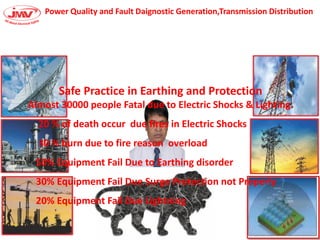
- 1. Power Quality and Fault Daignostic Generation,Transmission Distribution Safe Practice in Earthing and Protection Almost 30000 people Fatal due to Electric Shocks & Lighting. 20 % of death occur due fires in Electric Shocks 30 % burn due to fire reason overload 50% Equipment Fail Due to Earthing disorder 30% Equipment Fail Due Surge Protection not Properly 20% Equipment Fail Due Lightning
- 2. Sikhana to Padega Hi Follow NBC2016
- 4. Step Towards Staible Power •
- 5. Power Utiity
- 8. Safety Main It Should be Remain(Protect your Equipment for Surge Internal&External)
- 9. We are with you always
- 18. Standard IEC forPower Generation ,Transmission & Distribution
- 20. G M Generation Transmission Distribution Load Generation Transmission Distribution Consumption Electric Power Systems
- 21. JMV Offerings in Power Systems Substations Network Management Grid Systems Power Generation
- 23. Power Transmission & Distribution Network Secondary substation Distribution substation 400 / 220 kV 132/66/11 kV 110 / 132 kV 11/22 kV Transmission substation Main substation 400 V Transformer
- 24. Technology Options • Equipment – SDH (Synchronous Digital Hierarchy) – DWDM (Dense Wave Digital Multiplexing) – IP/MPLS (Multi Protocol Label Switching) JMV LPS LTD 24 OPGW 24 F OPGW Tower Repeater Tower with JB Tower POWERGRID S/S POWERGRID S/S City PoP City PoP Intracity Ring N/W Intracity Ring N/W OPGW 24 F OPGW Approach Cable U/G OFC 24 F U/G OFC 24 F SDH Access Eqpt. Shelter DG set SDH/ OADE SDH Access Eqpt. SDH/ OADE
- 25. Power System Transmission Lines: Electrical Characteristics
- 27. Phase Measurement UnitThe various features of PMUs are given below as follows: • PMUs are Measures 0/ 0 Hz AC a efor s oltage a d urre t typi ally at a rate of 8 samples per cycle. • PMUs are the o puted usi g DFT-like algorithms, and time stamped with a GPS. • The resulta t ti e tagged PMUs a e tra s itted to a lo al or re ote re ei er at rates up to 60 samples per cycle.
- 28. IEC 61850 Substation Communication Network Architecture for Efficient Energy System Automation High-speed peer-to-peer IEC 61850-8-1 GOOSE and IEC 61850-9-2 sampled values based information-exchange among IEDs in modern IEC 61850 substations have opened the opportunity for designing and developing innovative all-digital protection applications. The transmission reliability and real-time performance of these SVs and GOOSE messages, over the process-bus network, are critical to realize these all-digital IEC 61850 substation automation systems (SASs) protection applications. To address the reliability, availability, and deterministic delay performance needs of SAS, a novel IEC 61850-9-2 process-bus based substation communication network (SCN) architecture is proposed in this article. Reliability of the proposed as well as the traditional process-bus based SCN architectures is evaluated using the reliability block diagram (RBD) approach. Network components are modeled, and end-to-end (ETE) time-delay performance is also evaluated for all-digital protection applications running on the SCN architectures simulated in the OPNET modeler platform. The reliability and performance results of the proposed architecture compared to the traditional architectures confirmed its highly reliable, fast, and deterministic nature.
- 29. Surge in Systems and Result
- 30. Surge in DC Application
- 34. Facts about Lightning • A strike can average 100 million volts of electricity • Current of up to 200,000 amperes • Can generate 54,000 oF • 10/350MicroSec/50KA Fault Current/Discharge in Nano Sec Protection Earthing Design100KA Fault Current/Joints Exothermic /Flexible Down Conductor with Shortest Route & Less Corner
- 35. • Lightning Protection Standard use in India (IS2309 Now IEC 62305-5)NBC2016 Working Principle Angullar No Compromise with Design Max Protection 30Mtrs from One No Product warrenty from Manufacturer High Maintenance Require NFC17-102(2011) Now Europeon Standard(ESE LA) Working Principle Radius Compromise with Design Possible with Increasing Qty of ESE Max Protection 109 Mtrs Radius from One Manufacturing Warrenty and Test Certificate for Products Available Maintenance on Call Basis
- 37. The Simple Rod air terminal is composed from a metallic rod with 2 to 8 m height dominating the structure to protect, and linked to 2 down conductors minimum, and 2 earthing systems. The protection radius ensured by this air terminal which is limited to 30 m more or less (Protection level IV, height = 60 m), especially dedicated to the protection of small structures or areas like to ers, hi eys, ta ks, ater to er, a te a asts… The EN 0 -3 standard describes the installation procedure for these air terminals. 13 Simple Rods, 13 down conductors, and 13 earthing systems are necessary to ensure the protection below :
- 38. The meshed cage protection is composed from a meshing in roof surface and in the front face around the uildi g. Surrou di g the roof surfa e, a d o high poi ts, apture poi ts are positio ed. A o du tors’ network is placed at the outer perimeter of the roof. This network is completed by transverse conductors. The size of the meshing is 5 to meters, and depends on the efficiency needed for the protection. On the front face of the building, the down conductors are linked at the top to the meshing of the roof. And, down, to specific earthing systems. The distance between two conductors is 10 to 25 meters, and depend on the efficiency needed for the protection. The EN 62305-3 describes the installation procedure for this method. Generally, this method is heavy and expensive, due to the complexity of the structures to protect. 26 capture points, 26 down conductors and a grounded loop earthing system are necessaries to ensure the protection of the structure here below :
- 39. The catenary wires protection is a method closed to the meshed cage principle, because it is constituted with meshing of the conductors far from the structure to protect, to avoid any contact with lightning current. Catenary wires are located over the structure to protect, connected to down conductors and specific earthing systems. The width of the meshing and distance between the down conductors must respect the same rules as for the meshed cage. The EN 62305-3 describes the installation procedure for this method. Generally, this method is heavy and expensive, due to the complexity of the structures to protect.
- 40. The ESE air terminal is a terminal which enables to generate artificially an upward leader earlier than a simple rod, with an ionization system, in order to establish a special impact on its point. The capture of the lightning strike being faster than a simple rod, this technology enables to benefit from larger protection areas, ensuring protection for large dimensions structures. The ge erated prote tio radius depe ds o the early strea er e issio alue of the air ter i al Δt i µs , its height, and the efficiency of the protection. The protection radius ensured by this type of air terminal is 120 m (Protection level IV, height = 60 m , early streamer emission time 60µs) The NFC 17-102 standard describes the installation procedure for this type of air terminal. The installation of this type of air terminal is easy and cheaper than other technologies. It can protect whole buildings with one E.S.E. air terminal. It enables the protection of a structure and its environment, the protection of opened areas and well integrate in the architecture of a structure without aesthetic alteration. 1 ESE, 2 down conductors and 2 earthing systems are necessary to ensure the protection below :
- 45. Line Filters
- 48. Use of SPD
- 49. Surge Protection in Circuit
- 51. Earthing Design and Require Result • For substation Large Power below 1.00Ohm • For substation Small Power below 2.00Ohm • SCADA/TELECOM and AutomationFor substation Large Power below 0.50Ohm • Tower and Other Structure between 8-15Ohm • Lightning Surge Protection 50KA below 5Ohm or 100KA between 8-15Ohm • Follow Standard IEC /IEEE • Recommended use of Hybrid Metal to Protect from Theft Copper Clad Steel/Alumineum Clad Copper • Exothermeic weld IEEE 837
- 53. Copper Clad Steel Solid ROD and Conductor
- 58. Copper Cladded Conductor For Electrical Installation The Copper Clad Steel Grounding Conductor is made up of steel with the coating of 99.99% pure copper. These conductors/ wires or strands are equipped with the strength of steel with the conductivity and copper with the better corrosion resistance property. The concentric copper cladding is metallurgic ally bonded to a steel core through a continuous, solid cladding process using pressure rolling for primary bonding. The copper cladding thickness remains constant surrounding steel. We use different steel grades for the steel core result in Dead Soft Annealed, High strength and Extra High Strength Characteristics. The Copper Clad Steel Wire yields a composite conductivity of 21%, 30% and 40% IACS, and available in Annealed and Hard drawn. We are delivering products with varied conductivity and tensile strength as per the customer need. Further, the wire can be processed to be silver plated or tinned copper clad steel wire.
- 59. Most Efficient JointProcess It is efficient and superior to all existing surface –to-surface mechanical retention connectors.
- 60. What is Exothermic Welding System? Copper to Bi-Metal and Alumenium Types of Exothermic Joints: Possible to join any bi metal except aluminum Exothermic welding is a process of making maintain free highly molecular bonding process is superior in performance connection to any known mechanical or compression-type surface-to-surface contact connector. Exothermic weld connections provide current carrying (fusing) capacity equal to that of the conductor and will not deteriorate with age. It offers Electrical connections between two or more copper to copper and copper to steel conductors. Highly portable method as it does not require any external power source or heat source, so it can be done almost anywhere. It provides strong permanent molecular bond among metallic conductors that cannot loosen and further will not deteriorate with age. Connection does not corrode with time and it offers permanent conductivity.
- 61. Installation ESE AT with radius protection form 32 mtr to 107 mtr. DMC Insulator . GI/FRP Mast . Down Conductor Copper / Copper Cadmium Cable 70 sq. mm Copper Bonded Ground Earthing
- 64. JMV’s Clients
- 65. Neeraj Saini – 9910398538 Rahul Verma – 9910398535 Manav Chandra - 9910398999 manav@jmv.co.in