SlideShare ist ein Scribd-Unternehmen logo
1 von 21
Downloaden Sie, um offline zu lesen
American Institute of Aeronautics and Astronautics
1
A Monte Carlo Simulation for Evaluating
Airborne Collision Risk in Intersecting Runways
M. Henry*
, S. Schmitz†
, K. Kelbaugh‡
, and N. Revenko‡
The MITRE Corporation, McLean, Virginia, 22102
I. Abstract
The Intersecting Operations simulation model was developed to derive a set of separation standards
for converging or intersecting runway operations to statistically mitigate airborne collision risk.
This simulation incorporates synthetic trajectory models that capture both the variability of
observed flight trajectories and the effects of environmental parameters. Through repeated Monte
Carlo trials, the simulation derives the relationship between a given spacing metric and the relative
likelihood of an airborne collision. An analyst may use this method to develop a strategy that
mitigates unacceptable risk by ensuring that aircraft avoid situations more likely to result in a
midair collision.
II. Introduction
he Intersecting Operations (IO) model provides a novel quantitative method to assess airborne collision risk at
or near the intersection of runways, or their extended centerlines in the case of converging runways. This
approach uses data-driven trajectory models that allow for the Monte Carlo simulation of aircraft operations on a
pair of runways. The statistical trajectory models previously introduced in “Data Driven Modeling for the
Simulation of Converging Runway Operations”1
are adapted to allow for the generation of random trajectories for
specified environmental conditions. This adaptation ensures that the resulting trajectories better match the observed
behavior of aircraft at a particular airport. This paper introduces the design of the Intersecting Operations simulation,
describes the development of trajectory models, and provides a notional case study for the application of the IO
model to derive a risk mitigation strategy.
III. Background
The Federal Aviation Administration (FAA) is chartered to ensure the efficient and safe use of the National
Airspace System (NAS). Efficient use of air space in proximity to major metropolitan airports is essential to meet
the demands of today’s NAS. This air space, the terminal environment, has the most dense air traffic in the NAS.
The FAA ensures safety throughout the NAS by instituting regulations and standards for commercial and private
aircraft operators and Air Traffic Control (ATC) services that ensure a consistent and high level of safety. Risks with
more serious consequences are guarded against with stricter safety thresholds, ensuring that such events occur less
frequently. The target level of safety (TLS) defines the maximum allowable probability of a given risk event
occurring (either per operation or per operational hour, as appropriate). The FAA Safety Management System
(SMS) manual categorizes risks by their severity and prescribes a TLS for each risk category.2
Midair collisions (MAC) are among the most severe events, and must be prevented through the use of the highest
safety levels. The SMS manual considers the severity of MAC events to be “catastrophic,” a category reserved for
*
Lead Aviation Systems Engineer, Department of Western/International Airports and Airspace, 7525 Colshire Dr.,
McLean, VA 22102 M/S N370, AIAA Member.
†
Senior Operations Research Analyst, Department of Operations Research and Systems Analysis, 7525 Colshire
Dr., McLean, VA 22102 M/S H617, AIAA Member.
‡
Senior Aviation Systems Engineer, Department of Western/International Airports and Airspace, 7525 Colshire Dr.,
McLean, VA 22102 M/S N370.
T
American Institute of Aeronautics and Astronautics
2
incidents likely to result in aircraft hull loss and multiple fatalities.2
MACs are so severe that a near midair collision
(NMAC), defined as a loss of separation of less than 500 feet between airborne aircraft,3
is itself considered a
“hazardous” event that must be prevented at a high level of safety. Prevention of NMAC events also ensures the
avoidance of midair collisions.
The terminal environment presents an elevated risk of NMAC events: a 2011 study found that 59% of the
reported NMAC events over a ten year period occurred in the airport environment.4
As previously mentioned,
NMACs are considered hazardous events, for which the SMS requires a TLS of one-in-ten-million (P(event) ≤ 10-7
).
However, the terminal airspace presents an additional NMAC risk: in airspace above 5,000 feet an Air Traffic
Controller (ATCO) can mitigate potential NMAC events by instructing one aircraft to descend and the other aircraft
to climb. In the terminal area, however, the close proximity to the ground prevents one of the aircraft from being
able to descend, making vertical separation more difficult. The SMS manual provides no explicit TLS for NMACs
in the terminal airspace. Consequently, we conservatively apply the TLS of a catastrophic event: one-in-one-billion
(P(event) ≤ 10-9
).2
Certain intersecting or converging runway pairs may present a high risk of NMAC events. Strategies based on
the spacing or timing between these two converging aircraft streams can establish sufficient aircraft separation and
mitigate these safety risks. To ensure that operational policy decisions meet the FAA safety standards required by
the SMS, the risk of NMACs must be properly quantified. The FAA has recognized that certain runway pairs could
have these high risks and the Air Traffic Organization Safety has requested that the Center for Advanced Aviation
System Development (CAASD), a Federally Funded Research and Development Center (FFRDC) operated by the
MITRE Corporation, investigate methods to mitigate potential NMACs in high-risk areas.
FAA Order 7110.65U, section 3-9-8 defines the rules for aircraft during converging and intersecting runway
operations. It mandates that ATCOs adequately separate departing aircraft from aircraft using an intersecting or
converging runway by ensuring that the departure does not begin take-off roll until one of the following conditions
are met5
:
The preceding aircraft has departed and passed the intersection, has crossed the departure runway,
or is turning to avert any conflict… A preceding arriving aircraft is clear of the landing runway,
completed the landing roll and will hold short of the intersection, passed the intersection, or has
crossed over the departure runway.5
The rules address the requirements for safe operations when departures take off from one runway while arrivals
land on a converging runway. However, if the arriving aircraft initiates a missed approach procedure at the same
time a departure takes off from a converging runway, the resulting intersecting flight paths create an airborne
collision risk. This risk is not explicitly addressed by the aforementioned rules and presents a hazard to the safe
conduct of arrival-departure operations. Missed approaches occur in approximately one-in-one-thousand flights and
are difficult to predict because of their infrequent occurrences. Further, they exhibit highly variable flight behavior
relative to arrivals. Due to the rarity of missed approach events, it is difficult for ATCOs to accurately estimate a
release time for departures so as to ensure it does not arrive at an intersection at the same time as an arrival, should
the arrival execute a last-minute missed approach maneuver. For this reason, mitigation strategies may aid ATCOs
in ensuring that the TLS is met when missed approach and departure flight paths intersect. One mitigation strategy is
the Arrival Departure Window (ADW), shown in Figure 1. This strategy defines a region, or window, along the
arrival approach such that a departure may be released only if no arrival occupies this window. The IO model is
capable of determining the boundaries of the ADW for a given airport configuration and would provide a useful tool
to aid ATCOs to reliably control converging arrival-departure operations even in the event of missed approaches.
American Institute of Aeronautics and Astronautics
3
Figure 1. Application of an Arrival Departure Window operation. On the left, an arriving aircraft is within the ADW
boundaries, so the departure is held. On the right, no arriving aircraft is within the ADW, so the departure may be
released.
The IO model is not restricted to examining only ADW cases. The simulation can examine any combination of
arrivals, departures, and missed approaches on intersecting or converging runways. Depending on the specific
scenario, different spacing or timing metrics may be used to mitigate collision risk.
IV. Modeling Approach
The IO simulation model provides a capability for producing data-driven and repeatable safety analyses that
quantify the safety risk at intersecting or converging runways. A key feature of this simulation is its use of data to
inform its analysis. Available radar data, comprising hundreds of thousands of flights, are processed to create
statistical trajectory models that accurately represent the aircraft operational performance. These models additionally
capture the effect of environmental parameters (e.g. wind and temperature) on the aircraft trajectories. The
simulation incorporates these trajectory models into an operational environment that determines how the risk of
airborne collision depends on various operational parameters.
A. Data Sources, Filtration and Processing
The empirical data utilized in trajectory development come from an amalgamation of official FAA data sources
made available to the MITRE Corporation. Positional flight radar data are gathered through the National Offload
Program (NOP) which is comprised of the Automated Terminal Radar System (ARTS)*
and Standard Terminal
Automation Replacement System (STARS)†
facilities. These facilities provide historical track data in the enroute
and terminal environment at a four second update rate. This data are joined with Airport Surface Detection
Equipment, Model X (ASDE-X)‡
radar data, which provide a more accurate estimate of aircraft position in the
terminal environment, particularly at or near the ground, at an update rate of one second. A MITRE product known
as Threaded Track performs mixed curve smoothing algorithms to combine these overlapping radar data sources
into a single estimated trajectory. These interpolated flight trajectories are joined with environmental and flight
metadata. These flight metadata include runway geometries and elevations sourced from the National Flight Data
*
ARTS versions IIE and IIIE are currently operating in the NAS. Version IIE systems are designed to support up to
two sensors, each capable of processing as many as 256 simultaneous radar tracks. Version IIIE systems are
designed to support up to 15 sensors and as many as 10,000 simultaneous radar tracks. URL:
http://www.faa.gov/air_traffic/technology/tamr/arts/
†
STARS facilities are replacing current ARTS facilities and synchronize data from as many as 16 radar sensors.
These systems are designed to support up to 1,350 simultaneous tracks over distances as far as 60 miles away.6
‡
ASDE-X combines “surface movement radar located on the air traffic control tower or remote tower,
multilateration sensors, ADS-B (Automatic Dependent Surveillance-Broadcast) sensors, the terminal automation
system, and aircraft transponders” to track aircraft within a five mile radius.7
Release
Departure
ADW
Missed
Approach
Departure
ADW
Missed
Approach
Departure
Hold
Departure
STOP
American Institute of Aeronautics and Astronautics
4
Center (NFDC).*
The environmental data are derived from various sources, including the National Weather
Service’s Automated Surface Observing Systems (ASOS)†
data source and the National Oceanic and Atmospheric
Administration’s Rapid Update Cycle (RUC)‡
zero-hour predictions.
These data, consisting of more than two years of air traffic across the NAS, are stored and processed using
Apache™ Hadoop®. This open source software uses distributed processing across a computer cluster to enable
efficient analysis of large datasets. This distributed system reduces the necessary time to obtain desired subsets of
the data. For instance, an analyst may wish to select only flights from a specific airport, or only flights of a certain
type of aircraft; because the dataset is large, these tasks can be accomplished in less time using a distributed file
system as compared to a traditional relational database.
Before a trajectory model can be created for a specific aircraft type, it is necessary to obtain a representative
dataset of aircraft trajectories. For aircraft types that are less common in the NAS, it may be necessary to use all
available observed trajectories within the dataset. For common aircraft types, however, it may not be worthwhile to
include every observation in the analysis. When obtaining only a subset of the available data, it is important to
ensure that this sample exhibits the full range of flight behaviors of the full dataset and is drawn from a variety of
environmental conditions. For this reason, our samples were selected from airports across the NAS over different
days throughout the year.
These samples are further filtered for erroneous data that may be an artifact of radar bias introduced during
trajectory smoothing. Each flight operation of interest (i.e. arrival, departure, or missed approach) is identified and
isolated for further data filtration. Missed approaches are identified by flagging flights that align with a runway and
descend at least 500 feet, and then climb at least 450 feet over a period of at least one minute, followed by a turn of
at least 90 degrees before landing. The point of lowest approach during the execution of the missed approach is
identified as the estimate of the missed approach point. In the absence of operator flight data, this method for
approximating the missed approach point is our closest approximation of the actual event. Once these steps have
been completed, each sample is bundled and stored to be later used for trajectory modeling.
B. Trajectory Model Development
1. Data-Driven Trajectory Models Using Principal Component Analysis
To obtain reliable simulation results, simulated aircraft behavior must reflect actual aircraft behavior. As
described above, MITRE maintains a large amount of historical radar track data of domestic flights. A simple
approach to ensure accuracy of simulated behavior would be to have the simulation randomly sample from these
available historical trajectories. However, the number of available observations is insufficient for the large number
of repeated trials required by the Monte Carlo simulation.
The use of an analytic model of aircraft trajectories allows for the creation of an infinite number of unique
trajectories, avoiding the shortcomings of empirical sampling. A common approach to aircraft trajectory modeling is
to use an underlying physics model combined with aircraft performance specifications, and environmental
parameters to predict an aircraft’s position. Randomness in such a model can be achieved by applying some amount
of random variation to the input, the output, or both.
As noted by Eckstein,1
such models are not always able to capture the full amount of variability exhibited by
actual aircraft trajectories. Instead, the author proposes the use of a data-driven model using Principal Component
*
NFDC is an FAA compendium of current and historical aeronautical information of the physical description,
geographical position, and operational characteristics for all components within the NAS. URL:
https://nfdc.faa.gov/xwiki/bin/view/NFDC/NFDC+Mission
†
ASOS provides ground weather observations from more than 900 weather stations located at metropolitan and
regional airports throughout the NAS. URL: http://www.srh.noaa.gov/jetstream/remote/asos.htm
‡
RUC is a high frequency weather forecast prediction algorithm that assimilates an amalgam of weather reporting
data sources to determine the best zero to multi-hour forecast estimate.8
American Institute of Aeronautics and Astronautics
5
Analysis (PCA). PCA performs an orthogonal basis transformation on a multivariate dataset. The resulting
transformed variables are called principal components. This transformation is accomplished as follows:
where X is the original dataset*
(oriented such that there is a row for each observation and a column for each
variable), C is the transformed data, and M is the new basis matrix. PCA chooses this new basis such that each
principal component captures as much of the variability of the data as possible while still being orthogonal to all
preceding components. It can be shown that this is accomplished by choosing the columns of M to be the
eigenvectors of the covariance matrix XT
X, arranged in descending order of the corresponding eigenvectors.†,9
PCA has several useful properties. First, the principal components are all linearly uncorrelated with one another.
Additionally, PCA is often used to reduce the dimensionality of a dataset while retaining as much information as
possible.9
As presented above, C has the same dimensions as X, and no information has been lost. Suppose however,
that only the first N components are retained, and the rest are discarded. The formula for this truncated
transformation is given by:
where MN is the truncated basis matrix obtained by the first N columns of M, and CN contains the truncated
representation of the data using only the first N principal components. Geometrically, this corresponds to a
projection of the multivariate data onto a lower dimensional hyperplane. If the columns of X are linearly
independent this transformation necessarily losses some amount of the original information. The geometric
interpretation of these loses is the difference between the original data points and their projections. Recall that each
succeeding principal component captures less of the total variation of the dataset than all preceding components. As
a consequence, the truncated principal component representation has minimized the amount of information lost by
the reduction in dimensions. More precisely, the choice of the truncated basis has minimized the sum of squared
errors between the original data and its projection.9
The amount of information lost in this dimensional reduction depends on the amount of correlation between
different variables of the multivariate dataset. In the worst case, if all dimensions of X are linearly uncorrelated with
one another, then PCA provides no additional benefit, and the truncated transformation is equivalent to retaining
only those dimensions with the most variance. In practice, however, there is often a significant amount of correlation
between different variables of a dataset, allowing for the vast majority of the variability to be obtained in a much
smaller number of principal components.
Before PCA can be applied to trajectory modeling, it is necessary to obtain a dataset that describes the empirical
aircraft trajectories in a consistent manner. For the purposes of our analysis, only three possible aircraft operations
are allowed: a departure, an arrival, or a missed approach. Because the trajectories of these three operations are very
distinct from one another, trajectories are grouped into separate datasets for each operation. Different aircraft types
may have very different performance characteristics that lead to distinct trajectories. Therefore, the data are
additionally segregated by aircraft type. In order to make consistent comparisons between observations, a common
reference time was necessary. This reference time was chosen to be the throttle up time‡
for departures; the touch
down time for arrivals; and the moment of missed approach initiation for missed approaches.
The departure trajectory models from Eckstein1
consisted of observed groundspeeds at one second intervals
relative to this reference time to define a “speed profile” for each empirical trajectory. If all departures are assumed
*
In this discussion of PCA, the dataset X is assumed to have a mean of zero. Mean centering the data before
applying PCA ensures that this condition is met.
†
In practice, the principal components can typically be computed more quickly using the Singular Value
Decomposition (SVD) of the data. However, the eigenvalue decomposition method described here is traditionally
associated with PCA and provides a more intuitive explanation of the process.9
‡
“Throttle up time” is defined as the moment at which the aircraft begins its rapid acceleration for takeoff.
American Institute of Aeronautics and Astronautics
6
to be positioned at the runway threshold at the throttle up time, then this speed profile is sufficient to reconstruct the
lateral trajectory of the aircraft if it were to travel straight along the extended runway centerline. Because the speed
of an aircraft at a given point in time is highly correlated with its speed one second before and one second after,
PCA is well suited to reduce the number of dimensions of the dataset without losing much of the underlying data.
For the example trajectory model in Eckstein1
only 20 principal components were necessary to capture 99.5% of the
total variability of a 180 variable data set.
After PCA had been applied to these speed profiles, the author fit separate distributions to the observed values of
each component. To create a random trajectory, an independent random sample was taken from each of these
distributions. These randomly generated principal component values were then converted back into the full
dimensional space of the trajectory by applying the inverse of the truncated basis matrix:
where SN is a 1xN vector of the randomly drawn sample of principal components, and V is the resulting speed
profile. Although each principal component was generated independently, multiplying by the matrix MN
T
ensures
that the resulting variables in V exhibit the proper linear correlation between one another.
The use of PCA results in a model that accurately captures the full variability exhibited by empirical trajectories.
Such models are data-driven and require no assumptions regarding aircraft performance parameters. As an
additional benefit, these models greatly reduce the dimensionality of the dataset: to generate a single speed profile of
180 variables, only 20 random numbers must be generated. This dimensional reduction allows for efficient trajectory
generation. Since the Monte Carlo simulation relying on these trajectories requires a large number of repeated trials,
an efficient method of generating trajectories is necessary in order to produce meaningful analysis in a timely
manner.
2. Modeling Environmental Conditions
As mentioned above, the PCA trajectory models used by Eckstein1
have two primary advantages: they are able
to accurately capture the full amount of variability exhibited in observed trajectories; and they can be generated in a
computationally efficient manner. As outlined by the author, these models capture only the straight-line trajectory of
the aircraft by describing the speed profile, while our simulation requires trajectories to additionally represent the
vertical behavior of aircraft. The PCA trajectory modeling methodology is easily extended to accommodate this
need by simply doubling the dimensionality of the original dataset by capturing both ground speed and altitude at
each second. After this increase in dimensionality, we now retain 30 principal components to account for 99.5% of
the total variability of the data.
Environmental conditions provide a more challenging modeling problem. Different aspects of the environment
in which an aircraft operates may affect the trajectory of that aircraft. For instance, atmospheric conditions,
especially wind and temperature can have a significant impact on aircraft performance. All else being equal, a
departing aircraft experiencing a strong headwind will be able to climb faster than the same aircraft with a tailwind;
similarly, colder air, due to its higher density, also enables aircraft to gain altitude more quickly.
Within a single trial of the Monte Carlo simulation, the two aircraft are generated independently of one another.
However, the environmental conditions between two aircraft at the same airport at the same time should be
consistent.*
If one aircraft is flying in cold weather and is therefore able to climb quickly, the other aircraft should be
experiencing the same low temperature and therefore also be more likely to climb quickly.
Eckstein1
proposes that such environmental conditions can be appended as additional variables in the dataset on
which PCA is performed. In this approach, when random trajectories are generated a random environment for that
trajectory is simultaneously created. Each environmental variable that is generated is a linear combination of the
*
Consistency of the winds experienced by each aircraft is dependent on the runway geometry. The wind speed and
direction must be consistent between the two aircraft, but depending on the orientation of the two runways, a
headwind experienced by one of the aircraft might correspond to a crosswind to the other aircraft, or vice versa.
American Institute of Aeronautics and Astronautics
7
randomly sampled independent principal component distributions. Under this approach, it is not possible to directly
create a trajectory for a desired environment. Instead, to ensure that the two trajectories are consistent with one
another, each data model must be iteratively sampled until a matching pair of trajectories is found such that their sets
of environmental parameters are sufficiently similar to one another.
While this repeated sampling approach is feasible, it comes at a significant computational cost. In order to find
two trajectories with matching environmental conditions, it may be necessary to generate many trajectories.
Moreover, this approach merely ensures that the environmental conditions between the two trajectories match each
other; it does not ensure that the distribution of generated conditions match that of the given airport. If we instead
require that the environmental conditions of each trajectory must match a randomly observed environment from the
given airport, this repeated sampling method becomes less efficient. Additionally, if we wish to condition on more
environmental parameters, this approach becomes even more computationally expensive.
3. Regression-PCA Hybrid Trajectory Models
To better account for the effects of environmental conditions, we extend the work of Eckstein1
by combining the
PCA approach with linear regression. These hybrid models enable the direct generation of random trajectories for a
specific environment.
The regression-PCA hybrid begins by using the same dataset as used by the repeated sampling method of the
previous section. However, in this new approach the environmental conditions, while recorded for each observed
trajectory, are not included in the PCA decomposition. The principal components created here are the same as those
from the original PCA method before environmental variables were considered. In the original approach we
proceeded by fitting distributions to each component. Instead, we now regress each principal component on the
desired environmental variables. A distribution is then fit to the observed residuals of this regression model which is
illustrated in Figure 2.
Figure 2. Illustration of the Regression-PCA hybrid approach. On the right, the observed values of a principal component
are regressed on an environmental variable, such as wind or temperature. On the left, a distribution is then fit to the
residuals.
To generate a random trajectory for a specific environment, the predicted value of each principal component is
computed by substituting the desired environmental variables into the multiple linear regression model associated
with that component. Random residuals for each component then are drawn independently from the fitted
distributions. Each random principal component is simply the sum of the predicted value and the residual. As before,
we convert from the lower dimensional principal components back into the original dimensional space of the
trajectories by multiplying this vector of components by the transpose of the truncated basis matrix (MN
T
).
Environmental
PrincipalComponent
Residual
Probability
American Institute of Aeronautics and Astronautics
8
Computationally, this method is much quicker than the repeated sampling method. Within the full simulation,
the repeated sampling method took over 50 times as long as the regression-PCA approach to create the same number
of trajectories. The assumptions made by this new approach are similar to those of the sampling method: both
methods assume linear correlation between the variables being modeled and ignore higher order relationships
between variables. In the repeated sampling method, the PCA basis ensures the proper linear correlation between the
environmental variables and the other dimensions. In that approach, all output variables are simply different linear
combinations of the same set of randomly generated principal components. In the new hybrid approach, the multiple
linear regression models enforce the proper linear correlation between the environmental variables and the other
dimensions.
One problem that may arise from the use of these hybrid models is the potential for over extrapolation. The
multiple linear regression models used to capture the effects of environmental variables may not provide accurate
predictions for input variables far outside the scope of observed values. In such a case, these errant predictions
would result in the generation of principal component values far beyond their normal bounds, leading to unusual or
unrealistic trajectories. To avoid this problem, we restrict the input regression variables to their observed ranges. At
simulation runtime, if a trajectory is needed for an environment outside of this range, the extreme input variable is
replaced by the nearest allowable value. If simulated conditions are frequently outside the bounds of the
observations used to create the trajectory, then the model may not accurately capture the behavior of aircraft at this
airport. To minimize this occurrence, it is important to create trajectory models from observations having a large
variety of environmental conditions.
Figure 3. Comparison of altitude profiles under different environmental conditions.
Figure 3 above illustrates how the regression-PCA hybrid model produces trajectories consistent with our
intuition regarding the impact of wind and temperature on aircraft trajectories. The same aircraft departure model
was randomly sampled 100 times each for two different environmental scenarios: a low temperature, high headwind
scenario; and a moderate temperature, no wind scenario. Although there is still much variability within each
scenario, there is a clear trend in which trajectories created for the strong headwind, low temperature environment
exhibit faster rates of climb than those for the mild environment.
Adoption of the regression-PCA hybrid approach allows for the inclusion of additional environmental
parameters without having a noticeable impact on the speed of trajectory generation. Runway elevation was
included as an environmental variable, since the elevation of the airport can have a significant impact on the density
of air, particularly for high altitude airports. For longer runways, an aircraft may takeoff with more weight, which
No Wind,
Average Temp
Strong Headwind,
Low Temp
Time (seconds)
Altitude(meters)
American Institute of Aeronautics and Astronautics
9
could cause the aircraft to take longer to achieve rotation.*
To account for this phenomenon, runway length was also
added as an environmental variable.
The final regression parameter used by the model is the missed approach distance. This variable is defined as the
distance to the runway threshold at which the given arriving aircraft initiates a missed approach maneuver. As
previously mentioned, all trajectory models consist of speed and altitude profiles. In order for the simulation to
determine the position of the aircraft, it is necessary to give the trajectory some initial reference point. For
departures, the aircraft is assumed to be at the runway threshold at the first second of the trajectory. For missed
approaches, there needs to be an analogous reference point for the model. To achieve this, the missed approach
distance is used as a regression parameter for the model. In addition to providing a mechanism for placing the
aircraft within the simulation, this approach also allows for the simulation to match the observed distribution of
missed approach distances for the runway under examination. This helps ensure that the simulation better models the
particular behavior of aircraft using that runway.
4. Advantages of Regression-PCA Hybrid Trajectory Models
Regression-PCA hybrid trajectory models provide many advantages. Relying only on observed behavior, data-
driven models require no underlying knowledge of aircraft performance. These hybrid models accurately
approximate the distribution of observed trajectories. Figure 4 below shows how the randomly generated trajectories
of one aircraft model closely match the characteristics of observed trajectories.
Figure 4. Comparison of observed ground speed profiles to a random sample from the trajectory model.
Additionally, hybrid models allow for the creation of trajectories tailored to specific environmental conditions.
This feature enhances the accuracy of the resulting trajectories by better emulating airport-specific behavior.
Moreover, regression-PCA hybrid models can create these tailored trajectories in a computationally efficient
manner.
C. Simulation Design
The strength of the IO model emerges by incorporating high fidelity trajectory models into a simulation structure
that efficiently evaluates interactions between aircraft and accurately quantifies risk. This simulation provides a
data-driven repeatable analysis of a specific scenario. The IO model consists of a Monte Carlo simulation in which a
single pair of aircraft – one for each runway – is randomly generated for each trial. After a sufficient number of
trials, it is possible to determine the relationship between certain input parameters and the risk of separation loss
between the two aircraft. Due to the high level of safety for airborne collision risk, the IO model requires a large
number of iterations to adequately characterize this relationship.
The simulation framework sets the scenario to be evaluated and the structure of the simulation. Case-specific
inputs are collected to realistically represent the scenario environment. The simulation initialization phase
determines the operational trade space and establishes a strategy for placing aircraft in relation to one another to best
inform a given risk mitigation strategy. Trajectories are then generated and placed in a common coordinate frame.
Each iteration of the simulation computes the closest point of approach between the two aircraft. This distance –
*
Rotation occurs when the nose of the aircraft lifts off the ground during takeoff.
Time (sec)
GroundSpeed(knots)
0 20 40 60 80 100 120 140 160 180
0
50
100
150
200
250
300
Observed Trajectories
Time (sec)
GroundSpeed(knots)
0 20 40 60 80 100 120 140 160 180
0
50
100
150
200
250
300
Synthetic Trajectories
American Institute of Aeronautics and Astronautics
10
along with the various input parameters of the given trial – are recorded as output from the simulation. Further
statistical analysis of this output is used to determine a risk mitigation strategy.
For the remainder of the Simulation Design section we assume that the scenario under investigation is a risk
analysis of departures and missed approaches on converging runways, mitigated by the adoption of an ADW. For an
overview of ADWs refer to the description beginning on page 2 within the Introduction.
5. Operational Framework
The development of a robust operational framework is integral to effectively evaluating a specific scenario. Each
simulation run compares two independently generated operations at converging or intersecting runways. Since the
trajectory models are constrained to the terminal environment, all operations take place in proximity to a common
airport. The three types of modeled operations are departures, arrivals, and missed approaches. The IO model allows
any combination of these operations, but each combination may require unique modeling parameters or analysis
techniques.
Treating each operation as independent provides a conservative estimate of collision risk. In actual operations,
pilots may see and avoid other aircraft and controllers may intervene to prevent the aircraft from crossing paths.
These factors are difficult to quantify and are not directly handled within the simulation. For scenarios involving
missed approaches (such as an ADW study), there may not be sufficient time after the point of missed approach for
either the pilot or ATC to prevent a collision. For such analyses, treating operations as independent is not overly
conservative.
6. Simulation Inputs
One of the fundamental inputs to the simulation is the definition of an adverse event, referred to as a Test
Criteria Violation (TCV). Typically, we define a TCV as having occurred when two aircraft come within 500 feet of
one another. This definition of TCV is consistent with the definition of NMAC events provided on page 2 within the
Introduction. Closely associated with the definition of a TCV is the choice of a TLS. Since our TCV definition is
usually chosen to capture NMACs in the terminal airspace, we apply a TLS of a probability of 10-9
.*
The choice of
TLS will not affect the actual simulation structure but allows for an initial estimation of the necessary mitigation
strategy as the simulation progresses based on the completed runs.
The choice of TLS may also affect the number of Monte Carlo iterations necessary to satisfactorily complete the
safety analysis. Termination of the simulation occurs if the simulation determines that its results are sufficient to
accurately estimate a risk. A more detailed discussion of this process is provided in the Interaction Evaluation
section below. To ensure that the simulation terminates, a number for the maximum amount of simulation runs is
set.
Since the IO model seeks to provide a safety analysis that captures the unique characteristics of specific airports,
the simulation attempts to incorporate as many relevant case-specific details as possible. Accurate runway
information is necessary to provide the coordinate frame for the simulation analysis. NFDC resources provide
accurate geographic positions of runway surfaces and additional characteristics such as headings and displaced
thresholds. Runway lengths and elevations are necessary for trajectory generation and threshold locations, while
headings determine trajectory placement and orientation. The intersection point of the extended runway centerlines
is then calculated using geospatial formulas. This intersection point serves as the origin of a common Cartesian
coordinate system in which both trajectories are placed.
To simulate a scenario unique to a particular airport, operational details for existing runways are collected
through a combination of flight plan data and radar analysis. These sources include Threaded Track†
and the
*
Refer to page 2 in the Introduction for a discussion of this choice of TLS.
†
For a description of Threaded Track, refer to the description on page 3 in section IV.A. Data Sources, Filtration
and Processing.
American Institute of Aeronautics and Astronautics
11
Enhanced Traffic Management System (ETMS).*
Radar analysis is used to determine the fleet mix†
for each
runway. Other key operational inputs detail the behavior of missed approaches. The frequency of missed approaches
may differ from one runway to the next. Similarly, the distribution of distances from runway threshold at the point
of missed approach initiation is unique to a given runway. The simulation uses the observed missed approach
behavior of the actual runway to determine these parameters.
Trajectory models lack a lateral component, so heading change characteristics are necessary to allow simulated
aircraft to turn as the aircraft gains altitude. In the simplest case, a maximum allowable heading change is identified
and a truncated normal distribution is sampled to determine heading changes. Alternatively, observed radar data of a
given runway or procedure may be used to determine an empirical distribution of heading changes.
For the trajectory models, environmental parameters are necessary to create trajectories representative of certain
wind and temperature conditions. ASOS reports over an entire year at the given airport provide an empirical
distribution of winds and temperatures. These meteorological conditions are generally dependent on the time of day.
Because more operations are conducted during the day than overnight, each ASOS report is weighted by a factor
proportional to the number of operations conducted during the time of day of that report. Airports often change
which runways are in use in response to the prevailing winds. For this reason, the wind distribution for which a
given configuration may be used is not the same as the distribution of all winds observed at that airport. To account
for this fact, we place limits on the allowable headwinds, crosswinds, and tailwinds of each runway. These limits are
separate parameters of the simulation and can be changed as appropriate. If a given ASOS report violates one of
these limits for either runway, it is omitted from the sample used by the simulation.
For all the input parameters, in some cases there may not be sufficient empirical data for an existing operation or
proposed operation. In these cases, input parameters may use data from a similar scenario or designed by the user to
model a hypothetical operation. The combination of all of these input parameters provides a detailed
characterization of an operation, allowing the simulation to best model the given scenario.
7. Simulation Initialization
Utilizing the operational parameters for a given scenario, the IO model determines how trajectories are placed in
relation to each other in order to characterize each specific operational combination. The simulation requires an
independent variable to explore the possible interactions since each iteration of the simulation is a forced pairing of
two operations. For an ADW, we wish to explore the relative likelihood of an airborne collision given the position of
the missed approach aircraft at the moment the departure is released. The independent variable in this case is the
missed approach aircraft’s distance from the runway threshold at the departure’s throttle-up time. During the
simulation, the missed approach positions are selected randomly from a uniform distribution within the simulation
bounds. Over enough repeated trials, it is possible to determine the relationship between the position of the missed
approach aircraft at the time of the departure release and the probability of a TCV.
The approach for an ADW analysis may be extended to other types of analysis. For some operational
combinations, a time delay or a distance stagger might be used to relate the two operations. Different scenarios or
operational concepts may require a different simulation technique. It is important that the independent variable span
all of the areas where a safety risk exists. In most cases it is best to identify an operational concept where a variable
can be isolated and controlled to mitigate risk.
8. Flight Trajectory Generation
Once the simulation structure is set, the trajectories are generated. By selecting randomly from the fleet mix for
each runway, random aircraft pairings are created. For each simulation run, both aircraft must experience the same
wind and temperature. A random wind and temperature observation is sampled from the environmental data and
passed to the trajectory models to create a pair of tracks.
*
http://www.fly.faa.gov/Products/Information/ETMS/etms.html
†
The term “fleet mix” refers to the proportion of traffic represented by each aircraft make and model.
American Institute of Aeronautics and Astronautics
12
To produce large scale simulations, speed and computational efficiency quickly become issues. Generating a
single set of parameters and trajectories for each run is very inefficient. To address this concern, large batches of
simulations are created. Batches can be scaled based on the computation power of the system running the
simulation. Generally each batch contains tens of thousands of tracks and parameter sets. The parameter sets contain
trajectory pairing, weather data, missed approach points, heading changes, and track placement, which all are
randomly generated. The trajectory models then generate random trajectory sets to meet each scenario while
evaluating each model as few times as possible. For each batch run, all information necessary to analyze the
interaction of the two aircraft has been generated and exists in a completely random sequence. This randomness is
important if later a subset of analysis is needed; random ordering also allows for analysis of the convergence of a
risk estimation. Next, the simulation needs to place each pair of tracks in a common coordinate frame and analyze
interactions. Since the data for each run have already been created, the simulation distributes the work using parallel
processing, further increasing computational efficiency.
9. Interaction Evaluation
To analyze the interaction of each operational pair, the trajectories must be applied to the same coordinate frame
in space and time. All positions are relative to the intersection of the two runway headings. Departures start their roll
at the runway origin. Arrivals are placed relative to the runway by extending their estimated approach glideslope
with a reported threshold crossing height. Missed approaches are placed by the distance from runway threshold at
the time of their missed approach point. To time the two trajectories relative to one another, a common timeline is
constructed such that the reference time (i.e. throttle-up time, touchdown time, or missed approach time) of the first
aircraft occurs at time zero. The timing of the second aircraft is determined by the independent variable. In the
example of an ADW, the missed approach trajectory timing is chosen to ensure that at time zero the aircraft’s
distance to the runway threshold is exactly the value selected by the independent variable.
Each track is applied in the coordinate frame using speed, heading, and altitude to update their position as a
function of time. Heading changes are incorporated as departures gain altitude or as missed approaches climb after
missed approach initiation. Using interpolation for position and time the two-dimensional and three-dimensional
closest points of approach are calculated for each pair of tracks. The simulation then prepares the results for output.
The most important outputs are the basic parameters used to generate the tracks (including the independent variable)
and the observed closest point of approach. Many additional metrics are available as output for analysis in post-
processing. Often, speeds on approach and through the intersection are captured for analysis of outlier behavior. At
the end of each batch of simulations all outputs are written to a text file. Following the simulation, the results are
further analyzed to derive a risk mitigation strategy.
10. Simulation Output Analysis
After the simulation has terminated, the results are analyzed to quantify the effect that one or more independent
variables have on the likelihood of a TCV. This analysis seeks to determine the risk mitigations necessary to meet
the required TLS. By modeling the effect an independent variable has on the probability of a TCV, we can
determine the necessary restrictions to place on that variable in order to achieve the necessary TLS. To illustrate the
simulation output analysis, we use the ADW concept as an example of a risk mitigation strategy.
The goal of an ADW is to determine when it is safe to release a departure, given the position of an arrival on a
converging runway. In order to accomplish this goal, the output of the Intersecting Operations model includes the
independent variable: the position of the missed approach at the time of the departure’s release. The desire is to
model the distribution of these initial missed approach distances for cases that resulted in a TCV. This distribution
can be used to determine the necessary dimensions of the ADW to achieve a desired TLS.
We begin the risk calculation by including the likelihood that a departure would encounter a missed approach
during actual operations. Because each iteration of the simulation has a missed approach, this probability represents
each iteration’s likelihood of occurring. The probability of a missed approach within normal arrival operations is
usually on the order of one-in-one-thousand arrivals. This probability will be expressed as:
( )
American Institute of Aeronautics and Astronautics
13
Next we account for the probability that a given simulation iteration resulted in a TCV. This probability is
estimated using the rate of observed TCVs per run of the simulation. Each iteration is preconditioned by the
likelihood of an arrival executing a missed approach. This conditional probability is expressed as:
( ) ( )
The product of these two probabilities yields:
( ) ( ) ( )
Because the arrival runway is converging, we assume that there is no operational risk of a TCV unless the
arriving aircraft performs a missed approach. It follows therefore that the preceding probability also represents the
likelihood of a TCV occurring within normal operations:
( ) ( ) ( ) ( )
We must mitigate additional risk if the probability of a TCV, as shown above, is greater that the TLS. An ADW
provides a mechanism for mitigating this additional risk. The following probability describes the likelihood that a
given TCV occurred where the missed approach aircraft was outside of the bounds of the ADW at the time of
departure release:
( )
The probability of a TCV occurring when an ADW is applied is given by:
( ) ( ) ( ) ( )
In order to achieve the target level of safety, the following condition must hold:
( )
or equivalently:
( )
( ) ( )
This inequality provides the basis for determining the necessary boundaries of the ADW to achieve the TLS
which we refer to as the risk mitigation term. A distribution is fit to the initial missed approach distances that
resulted in TCVs. The risk mitigation term is evenly applied as quantiles on the upper and lower extremes of the
distribution. This provides the leading and trailing edges of an ADW.
11. Simulation Convergence
A benefit of Monte Carlo simulation is that iterations can be continuously run until the results achieve a desired
level of convergence. The IO model terminates when it estimates that its results have sufficiently converged. The
preceding section demonstrated how a risk mitigation strategy can be derived from the simulation output. The output
of the IO model describes the likelihood of a TCV as a function of the simulated independent variable. Quantiles of
a distribution fit to this output provide the necessary bounds of a risk mitigation strategy.
The IO model periodically estimates these bounds based on the results of completed iterations. By examining
the evolution of a given quantile over the course of the simulation, the IO model determines if the quantile is
converging. The simulation computes the standard deviation of these quantile estimates over the last 70% of the
previous iterations. This standard deviation characterizes the precision of the quantile estimates.
American Institute of Aeronautics and Astronautics
14
Additional simulation batches will continue to run until this convergence metric is sufficiently small or the
maximum number of simulations is reached. The simulation can also dynamically adjust batch sizes depending on
the degree of convergence of the quantile estimates.
V. Notional Case Study
This notional case study demonstrates the experimental design and workflow for the IO model. This example
analyzes a single set of converging operations; however, a holistic case study would examine all of the impacts of
possible interactions within an airport’s desired configuration. The following section starts by illustrating the setup
of the theoretical case; it describes the configuration, as well as the operational and environmental inputs utilized by
the IO model. We then discuss how the simulation progresses under the provided inputs. Furthermore, we describe
how simulation outputs are utilized to develop a controller mitigation strategy. In this case, an Arrival Departure
Window is evaluated for the example scenario.
A. Case
This case study evaluates an example case of a departure interaction with a converging missed approach. Both
runways are 7,000 feet in length and are positioned orthogonally. The runway configuration for this case study is
illustrated in Figure 5. Aircraft trajectories are allowed a maximum heading change of 5 degrees. The intersection
point of the arrival runway’s extended centerline with that of the departure runway, lies over the departure runway’s
surface. This configuration presents the common scenario where the arriving aircraft would not interact with the
departing aircraft if the arriving aircraft lands safely. The probability of a missed approach represents the risk to the
departing aircraft. For the theoretical case presented here, we approximate the missed approach rate to be one-in-
one-thousand.
Figure 5. Runway geometries for notional airport
Missed
Approach
Departure
7,000 ft
7,000 ft 2,500 ft
600 ft
American Institute of Aeronautics and Astronautics
15
Figure 6. Percentage of fleet mix by aircraft type
The fleet mix for the case is representative of that of a 7,000 foot runway within the NAS. Figure 6 provides a
histogram of the ten most frequent aircraft types. The DH8A is a prominent aircraft type in this analysis; this is a
small propeller aircraft which has significantly different performance from other more common jets in the NAS. The
DH8A’s markedly different performance profile from other aircraft can have a distinct effect on the outcome of the
simulation. Due to the effects of performance variation by aircraft, empirical data for the fleet mix is used whenever
possible. Controllers may wish to restrict an operation based on an aircraft type.
B. Environmental Data
The theoretical case study uses environmental data associated with the weather observed in the east coast region
of the NAS. Winds are mild, with 91% of observations below 15 knots. The airport’s altitude lies at 20 feet above
mean sea level and temperatures fluctuate between -4 and 30 degrees Celsius. Figure 7 shows the temperatures over
the course of a calendar year. Figure 8 provides a wind rose describing the wind directions and magnitudes of the
observed winds.
Figure 7. Local temperature range in a calendar year (°C)
0.0%
5.0%
10.0%
15.0%
A319 DH8A E170 CRJ2 CRJ7 A320 E135 E145 B752 MD82
-20
-10
0
10
20
30
40
50
60
1/1 2/1 3/1 4/1 5/1 6/1 7/1 8/1 9/1 10/1 11/112/1
American Institute of Aeronautics and Astronautics
16
Figure 8. Local range of winds in a calendar year
To be representative of real-world airport operations, the IO model limits extreme wind speeds. The restrictions
for this case are set to 25 knots of maximum head wind, 8 knots of maximum tail wind and 20 knots of maximum
cross wind. While operations may occur outside of these bounds, the intent is to ensure that the simulation operates
within nominal conditions in which the runway configuration is likely to occur.
C. Simulation
The IO model is a Monte Carlo simulation that requires numerous iterations to converge to a statistically
significant result. Within the analysis presented in this paper, the goal is to find the bounds of the ADW. Therefore,
convergence of the lower and upper bounds of the Arrival-Departure Window is determined over the course of the
simulation. To evaluate if additional simulations will change the ADW dimensions; the evolution of the bounds is
observed for the last 70 percent of the simulation. The bounds are said to sufficiently converge once the standard
deviation of the bounds becomes small enough; signaling a sufficient degree of precision. To estimate the bounds
within a tenth of a nautical mile we require that the standard deviation be within five hundredths of a nautical mile.
To better illustrate this concept, consider Figure 9 below.
Wind
Speed (kts)
American Institute of Aeronautics and Astronautics
17
Figure 9. Illustration of simulation convergence over time
Figure 9 depicts the simulation evolution of an Intersecting Operations model run with 1 million model
iterations. The horizontal axis provides iteration count. The vertical axis represents the distance in nautical miles
with respect to arrival runway threshold. Positive values indicate distances measured before the runway threshold as
the arrival was approaching, while negative values are distances measured after the runway threshold. The bounds of
the ADW are evaluated at frequent intervals during the simulation and are depicted within the figure. The upper line
represents the value of the approximated ADW’s upper bound, and the lower line represents the approximated
ADW’s lower bound. At the start of the simulation, with a relatively small number of TCVs observed, the
confidence in the fitted distribution is low. As the simulation continues, additional information on quantity and
characteristics of TCVs is collected. The Arrival-Departure Window bounds stabilize and the standard deviation of
the bounds decreases. The above depiction of the ADW does not constitute the final proposed bounds. This
evaluation is done with a preliminary distribution fit. The goal is to determine if there exists enough simulation data
to accurately provide parameter analysis during post processing. The final analysis incorporates the capabilities of
the analyst utilizing statistical tools to provide a thorough evaluation of the risk environment.
Standard Deviation < 0.05
American Institute of Aeronautics and Astronautics
18
D. Simulation Output Analysis
Once the simulation completes a sufficient number of iterations and precisely estimates Arrival-Departure
bounds, the ADW is calculated using simulation outputs. Simulation output data that the analyst needs to derive an
ADW include: (1) total number of iterations completed during simulation, (2) total number of iterations that resulted
in a Target Criterion Violation (these two numbers are needed to calculate the probability of a TCV), and (3) a set of
arriving aircraft locations filtered for arriving and departing aircraft which came within 500 feet of each other. The
analyst fits a theoretical distribution to (3) and determines the ADW bounds as described within the post-processing
section. A distribution fit to the simulation output from the case study is presented in Figure 10.
Figure 10. Histogram and fitted distribution of simulated TCVs (NM)
Table 1. Summary statistics of simulation output
The best fit to the TCV dataset of missed approach locations at the time of a departure is provided by the
Johnson SL distribution. The Shapiro-Wilk goodness-of-fit test produces a p-value of 0.76, as seen in Table 1.
Comparing this value to our significance level of 0.05, we fail to reject the null hypothesis that the dataset of
arriving aircraft locations is coming from the Johnson SL distribution. We proceed by evaluating the distribution
ADW
Summary Statistics
Mean 0.48907
Standard Deviation 0.27549
Standard Error Mean 0.00864
Upper 95% Mean 0.50602
Lower 95% Mean 0.47212
N 1017
Quantiles: Uncentered and Unscaled
Percentile Quantile
0.0004916 -0.27904
0.9995084 1.55811
Shapiro-Wilk Goodness-of-Fit Test
W Prob<W
0.998827 0.7609
Note: Ho = The data is from the Johnson
SL distribution. Small p-values reject Ho.
American Institute of Aeronautics and Astronautics
19
quantiles that correspond to the percentiles found from the risk equation. The positions of the quantiles represent the
lower and upper bounds of the ADW.
The number of iterations completed in the theoretical case was 1,000,000. The number of simulations that
resulted in a Target Criterion Violation was 1,017. The assumed missed approach rate was one-in-one-thousand. The
Target Level of Safety was 10-9
. Solving for the risk mitigation term results in the following:
( ) ( )
The lower bound of the ADW is given by the quantile representing half of this probability, 4.916-4
. The ADW
upper bound is similarly determined by the quantile representing a probability of (1-4.916-4
). The distances
corresponding to these two quantiles are 0.28 NM after the arrival runway threshold and 1.56 NM before the arrival
runway threshold. The resulting ADW is depicted in Figure 11.
Figure 11. Illustration of case study arrival departure window
VI. Conclusion
It has been shown that the IO model is an effective method for assessing the risk of terminal airspace NMAC
events for operations with intersecting or converging runways. This model accurately allows for analysts to ensure
that a consistent target level of safety is met for these operations through the calibration of various risk mitigation
strategies, such as an Arrival Departure Window. Regression and Principal Component Analysis are used to create a
trajectory model that characterizes the spectrum of flight variability in speed and altitude for given environments.
When the trajectory model is applied to a specific case, the simulated flights accurately represent the speed and
altitude of local traffic, making these models effective for simulating terminal airspace NMAC risk events.
ADW
1.56 NM
-0.28 NM
Missed
Approach
Departure
7,000 ft
7,000 ft 2,500 ft
600 ft
1.84 NM
American Institute of Aeronautics and Astronautics
20
The notional case study presented in this paper illustrates the application of the IO model to an analysis of
departures and missed approaches on converging runways. The development of mitigation strategies designed to
prevent terminal airspace NMAC events is an ongoing effort within CAASD.
VII. Acknowledgments
The authors would like to thank Adric Eckstein for providing peer review of this paper. Additionally, for Adric
Eckstein and Joe Clements for developing the initial flight trajectory modeling construct that allows for this work to
be possible. We would also like to thank John Lebron, Gregory Chesterton and Shweta Mulcare for their guidance
and copy-editing throughout the writing process.
VIII. Disclaimer
The contents of this material reflect the views of the author and/or the Director of the Center for Advanced
Aviation System Development. Neither the Federal Aviation Administration nor the Department of Transportation
makes any warranty or guarantee, or promise, expressed or implied, concerning the content or accuracy of the views
expressed herein.
Approved for Public Release; Distribution Unlimited. 13-2900 ©2013-The MITRE Corporation. All rights reserved.
American Institute of Aeronautics and Astronautics
21
IX. References
1
Eckstein, A., “Data Driven Modeling for the Simulation of Converging Runway Operations,” Fourth International
Conference on Research in Air Transportation (ICRAT), ICRAT, Budapest, Hungary, 2010, pp. 3-10.
2
Federal Aviation Administration, Air Traffic Organization. (2005, May 24). Air Traffic Organization, Safety Management
System Manual. Retrieved July 6, 2013, from Federal Avaiation Document Library:
http://www.faa.gov/air_traffic/publications/media/atosmsmanualversion2-1_05-27-08_final.pdf
3
Federal Aviation Administration. (2013, March 7). Aeronatical Information Manual. Retrieved July 6, 2013, from
http://www.faa.gov/air_traffic/publications/atpubs/aim/aim0706.html
4
Kunzi, F., and Hansman, R. J. (2011). Mid-Air Collision Risk and Areas of High Benefit for Traffic. AIAA Aviation
Technology, Integration, and Operations Conference. Virginia Beach, VA: AIAA. Retrieved from
http://www.avidyne.com/downloads/products/ads-b/MIT.Kunzi.MidAirs.pdf
5
Federal Aviation Administration, Air Traffic Organization Policy, “Order JO 7110.65U,” FAA, 2012. Federal Aviation
Administration Document Library [online document database], URL: http://www.faa.gov/documentlibrary/media/order/atc.pdf
[cited 26 July 2013].
6
Federal Aviation Administration, “Press Release – ‘STARS’ Shines in Cincinnati FAA Deploys Cornerstone of Air Traffic
Modernization in Cincinnati,” 2005, June 30, http://www.faa.gov/news/press_releases/news_story.cfm?newsId=6643&print=go
7
Federal Aviation Administration. (2010). Fact Sheet – Airport Surface Detection Equipment, Model X (ASDE-X).
Washington, D.C.: Federal Aviation Administration. http://www.faa.gov/news/fact_sheets/news_story.cfm?newsId=6296
8
Benjamin, S.G., D. Devenyi, S.S. Weygandt, K.J. Brundage, J.M. Brown, G.A. Grell, D. Kim, B.E. Schwartz, T.G.
Smirnova, T.L. Smith, and G.S. Manikin, 2004: An hourly assimilation/forecast cycle: The RUC. Monthly Weather Review.,
132, 495-518 (Feb. issue). http://ruc.noaa.gov/pdf/MWR-RUC-1hcyc-Sept03-final.pdf
9
Liang, Y. C., Lee, H.P., Lim, S. P., Lin, W. Z., Lee, K. H., and Wu, C. G., “Proper Orthogonal Decomposition and Its
Applications – Part I: Theory,” Journal of Sound and Vibration, Vol. 252, No. 3, 2002, pp. 527-544.

Weitere ähnliche Inhalte

Was ist angesagt?

Human-Machine Interfaces for Increased UAS Pilot Situational Awareness
Human-Machine Interfaces for Increased UAS Pilot Situational AwarenessHuman-Machine Interfaces for Increased UAS Pilot Situational Awareness
Human-Machine Interfaces for Increased UAS Pilot Situational Awarenessahuizote
 
Aviation - Infrastructure management
Aviation - Infrastructure managementAviation - Infrastructure management
Aviation - Infrastructure managementAkshaykumar More
 
5. naco’s approach to airside safety
5. naco’s approach to airside safety5. naco’s approach to airside safety
5. naco’s approach to airside safetyErika Souza
 
Airside Ops & Ntm
Airside Ops & NtmAirside Ops & Ntm
Airside Ops & NtmAiDY
 
FAA Guide to Operations - A Comprehensive Guide to Safe Driving on the Airpor...
FAA Guide to Operations - A Comprehensive Guide to Safe Driving on the Airpor...FAA Guide to Operations - A Comprehensive Guide to Safe Driving on the Airpor...
FAA Guide to Operations - A Comprehensive Guide to Safe Driving on the Airpor...FAA Safety Team Central Florida
 
Air Traffic Controllers Runway Condition Reporting
Air Traffic Controllers Runway Condition ReportingAir Traffic Controllers Runway Condition Reporting
Air Traffic Controllers Runway Condition ReportingÜlger Ahmet
 
Runway Condition Reporting
Runway Condition ReportingRunway Condition Reporting
Runway Condition Reportingapcae
 
09-Runway Configuration ( Highway and Airport Engineering Dr. Sherif El-Badawy )
09-Runway Configuration ( Highway and Airport Engineering Dr. Sherif El-Badawy )09-Runway Configuration ( Highway and Airport Engineering Dr. Sherif El-Badawy )
09-Runway Configuration ( Highway and Airport Engineering Dr. Sherif El-Badawy )Hossam Shafiq I
 
Automatic Landing of a UAV Using Model Predictive Control for the Surveillanc...
Automatic Landing of a UAV Using Model Predictive Control for the Surveillanc...Automatic Landing of a UAV Using Model Predictive Control for the Surveillanc...
Automatic Landing of a UAV Using Model Predictive Control for the Surveillanc...AM Publications
 
ACO-7 Emergency Aircraft Evacuation and Assistance
ACO-7 Emergency Aircraft Evacuation and Assistance ACO-7 Emergency Aircraft Evacuation and Assistance
ACO-7 Emergency Aircraft Evacuation and Assistance Brock Jester
 
Runway Incursion, Airport Signage and Markings - Presentation for future CFIs
Runway Incursion, Airport Signage and Markings - Presentation for future CFIsRunway Incursion, Airport Signage and Markings - Presentation for future CFIs
Runway Incursion, Airport Signage and Markings - Presentation for future CFIsThomas Bergen
 
Zlozenie wraku
Zlozenie wrakuZlozenie wraku
Zlozenie wrakuwikb
 
Modernisation of Avionics and C.N.S. Facilities
Modernisation of Avionics and C.N.S. FacilitiesModernisation of Avionics and C.N.S. Facilities
Modernisation of Avionics and C.N.S. FacilitiesAM Publications,India
 
Prelimary assessment-uap-20210625
Prelimary assessment-uap-20210625Prelimary assessment-uap-20210625
Prelimary assessment-uap-20210625BabelNews
 
10-Intersection Control ( Transportation and Traffic Engineering Dr. Sheriff ...
10-Intersection Control ( Transportation and Traffic Engineering Dr. Sheriff ...10-Intersection Control ( Transportation and Traffic Engineering Dr. Sheriff ...
10-Intersection Control ( Transportation and Traffic Engineering Dr. Sheriff ...Hossam Shafiq I
 

Was ist angesagt? (20)

Human-Machine Interfaces for Increased UAS Pilot Situational Awareness
Human-Machine Interfaces for Increased UAS Pilot Situational AwarenessHuman-Machine Interfaces for Increased UAS Pilot Situational Awareness
Human-Machine Interfaces for Increased UAS Pilot Situational Awareness
 
Aviation - Infrastructure management
Aviation - Infrastructure managementAviation - Infrastructure management
Aviation - Infrastructure management
 
5. naco’s approach to airside safety
5. naco’s approach to airside safety5. naco’s approach to airside safety
5. naco’s approach to airside safety
 
Airside Ops & Ntm
Airside Ops & NtmAirside Ops & Ntm
Airside Ops & Ntm
 
FAA Risk Management
FAA Risk ManagementFAA Risk Management
FAA Risk Management
 
Prevent Aerodynamic Stalls at Low Altitude
Prevent Aerodynamic Stalls at Low AltitudePrevent Aerodynamic Stalls at Low Altitude
Prevent Aerodynamic Stalls at Low Altitude
 
FAA Guide to Operations - A Comprehensive Guide to Safe Driving on the Airpor...
FAA Guide to Operations - A Comprehensive Guide to Safe Driving on the Airpor...FAA Guide to Operations - A Comprehensive Guide to Safe Driving on the Airpor...
FAA Guide to Operations - A Comprehensive Guide to Safe Driving on the Airpor...
 
Air Traffic Controllers Runway Condition Reporting
Air Traffic Controllers Runway Condition ReportingAir Traffic Controllers Runway Condition Reporting
Air Traffic Controllers Runway Condition Reporting
 
Runway Condition Reporting
Runway Condition ReportingRunway Condition Reporting
Runway Condition Reporting
 
FAA Risk Management
FAA Risk ManagementFAA Risk Management
FAA Risk Management
 
09-Runway Configuration ( Highway and Airport Engineering Dr. Sherif El-Badawy )
09-Runway Configuration ( Highway and Airport Engineering Dr. Sherif El-Badawy )09-Runway Configuration ( Highway and Airport Engineering Dr. Sherif El-Badawy )
09-Runway Configuration ( Highway and Airport Engineering Dr. Sherif El-Badawy )
 
Automatic Landing of a UAV Using Model Predictive Control for the Surveillanc...
Automatic Landing of a UAV Using Model Predictive Control for the Surveillanc...Automatic Landing of a UAV Using Model Predictive Control for the Surveillanc...
Automatic Landing of a UAV Using Model Predictive Control for the Surveillanc...
 
ACO-7 Emergency Aircraft Evacuation and Assistance
ACO-7 Emergency Aircraft Evacuation and Assistance ACO-7 Emergency Aircraft Evacuation and Assistance
ACO-7 Emergency Aircraft Evacuation and Assistance
 
Runway Incursion, Airport Signage and Markings - Presentation for future CFIs
Runway Incursion, Airport Signage and Markings - Presentation for future CFIsRunway Incursion, Airport Signage and Markings - Presentation for future CFIs
Runway Incursion, Airport Signage and Markings - Presentation for future CFIs
 
Zlozenie wraku
Zlozenie wrakuZlozenie wraku
Zlozenie wraku
 
Modernisation of Avionics and C.N.S. Facilities
Modernisation of Avionics and C.N.S. FacilitiesModernisation of Avionics and C.N.S. Facilities
Modernisation of Avionics and C.N.S. Facilities
 
LEVEL 2 ADA 2010
LEVEL 2 ADA 2010LEVEL 2 ADA 2010
LEVEL 2 ADA 2010
 
Airside Hazards And Risks
Airside Hazards And RisksAirside Hazards And Risks
Airside Hazards And Risks
 
Prelimary assessment-uap-20210625
Prelimary assessment-uap-20210625Prelimary assessment-uap-20210625
Prelimary assessment-uap-20210625
 
10-Intersection Control ( Transportation and Traffic Engineering Dr. Sheriff ...
10-Intersection Control ( Transportation and Traffic Engineering Dr. Sheriff ...10-Intersection Control ( Transportation and Traffic Engineering Dr. Sheriff ...
10-Intersection Control ( Transportation and Traffic Engineering Dr. Sheriff ...
 

Ähnlich wie A monte carlo simulation for evaluating airborne collision risk in intersecting runways

Simulation_Final_Project_Grp6.pptx
Simulation_Final_Project_Grp6.pptxSimulation_Final_Project_Grp6.pptx
Simulation_Final_Project_Grp6.pptxShivamPandey521834
 
VANET BASED SECURED ACCIDENT PREVENTION SYSTEM
VANET BASED SECURED ACCIDENT PREVENTION SYSTEMVANET BASED SECURED ACCIDENT PREVENTION SYSTEM
VANET BASED SECURED ACCIDENT PREVENTION SYSTEMIAEME Publication
 
ATCAJournal.Q4.2014.Article_Li
ATCAJournal.Q4.2014.Article_LiATCAJournal.Q4.2014.Article_Li
ATCAJournal.Q4.2014.Article_LiStefan Groenendal
 
Air Traffic Control Database Management System for Seamless Transit
Air Traffic Control Database Management System for Seamless TransitAir Traffic Control Database Management System for Seamless Transit
Air Traffic Control Database Management System for Seamless TransitIRJET Journal
 
Control of aircraft from the base station using eog siganl transmission
Control of aircraft from the base station using eog siganl transmissionControl of aircraft from the base station using eog siganl transmission
Control of aircraft from the base station using eog siganl transmissiontheijes
 
Control of aircraft from the base station using eog siganl transmission
Control of aircraft from the base station using eog siganl transmissionControl of aircraft from the base station using eog siganl transmission
Control of aircraft from the base station using eog siganl transmissiontheijes
 
Understanding the Power of the Schneider Electric Enhanced Flight Hazard Prod...
Understanding the Power of the Schneider Electric Enhanced Flight Hazard Prod...Understanding the Power of the Schneider Electric Enhanced Flight Hazard Prod...
Understanding the Power of the Schneider Electric Enhanced Flight Hazard Prod...Schneider Electric
 
Air traffic control
Air traffic controlAir traffic control
Air traffic controlAravind Raj
 
SAFETY MEASURES FOR TABLE-TOP RUNWAY OF MANGALORE AIRPORT
SAFETY MEASURES FOR TABLE-TOP RUNWAY OF MANGALORE AIRPORTSAFETY MEASURES FOR TABLE-TOP RUNWAY OF MANGALORE AIRPORT
SAFETY MEASURES FOR TABLE-TOP RUNWAY OF MANGALORE AIRPORTPranamesh Chakraborty
 
Goman, Khramtsovsky, Shapiro (2001) – Aerodynamics Modeling and Dynamics Simu...
Goman, Khramtsovsky, Shapiro (2001) – Aerodynamics Modeling and Dynamics Simu...Goman, Khramtsovsky, Shapiro (2001) – Aerodynamics Modeling and Dynamics Simu...
Goman, Khramtsovsky, Shapiro (2001) – Aerodynamics Modeling and Dynamics Simu...Project KRIT
 
Future Integrated Systems Concept for Preventing Aircraft Loss-of-Control (L...
Future Integrated Systems Concept for Preventing Aircraft Loss-of-Control (L...Future Integrated Systems Concept for Preventing Aircraft Loss-of-Control (L...
Future Integrated Systems Concept for Preventing Aircraft Loss-of-Control (L...University of Gujrat, Pakistan
 
Ieeepro techno solutions ieee 2014 embedded project next-generation airbo...
Ieeepro techno solutions    ieee 2014 embedded project  next-generation airbo...Ieeepro techno solutions    ieee 2014 embedded project  next-generation airbo...
Ieeepro techno solutions ieee 2014 embedded project next-generation airbo...srinivasanece7
 
ANALYZING AIRCRAFT LANDING DECISIONMAKING THROUGH FUZZY LOGIC APPROACH: A COM...
ANALYZING AIRCRAFT LANDING DECISIONMAKING THROUGH FUZZY LOGIC APPROACH: A COM...ANALYZING AIRCRAFT LANDING DECISIONMAKING THROUGH FUZZY LOGIC APPROACH: A COM...
ANALYZING AIRCRAFT LANDING DECISIONMAKING THROUGH FUZZY LOGIC APPROACH: A COM...ijseajournal
 
Batangas Airport Philippines.pdf
Batangas Airport Philippines.pdfBatangas Airport Philippines.pdf
Batangas Airport Philippines.pdfssuser553bbc
 
Edge computing for CAVs and VRU protection
Edge computing for CAVs and VRU protection Edge computing for CAVs and VRU protection
Edge computing for CAVs and VRU protection Carl Jackson
 
Lancaster_SFTY330_Paper_Final
Lancaster_SFTY330_Paper_FinalLancaster_SFTY330_Paper_Final
Lancaster_SFTY330_Paper_FinalAaron Lancaster
 
Ieeepro techno solutions 2013 ieee embedded project emergency messaging for...
Ieeepro techno solutions   2013 ieee embedded project emergency messaging for...Ieeepro techno solutions   2013 ieee embedded project emergency messaging for...
Ieeepro techno solutions 2013 ieee embedded project emergency messaging for...srinivasanece7
 

Ähnlich wie A monte carlo simulation for evaluating airborne collision risk in intersecting runways (20)

Simulation_Final_Project_Grp6.pptx
Simulation_Final_Project_Grp6.pptxSimulation_Final_Project_Grp6.pptx
Simulation_Final_Project_Grp6.pptx
 
VANET BASED SECURED ACCIDENT PREVENTION SYSTEM
VANET BASED SECURED ACCIDENT PREVENTION SYSTEMVANET BASED SECURED ACCIDENT PREVENTION SYSTEM
VANET BASED SECURED ACCIDENT PREVENTION SYSTEM
 
ATCAJournal.Q4.2014.Article_Li
ATCAJournal.Q4.2014.Article_LiATCAJournal.Q4.2014.Article_Li
ATCAJournal.Q4.2014.Article_Li
 
Air Traffic Control Database Management System for Seamless Transit
Air Traffic Control Database Management System for Seamless TransitAir Traffic Control Database Management System for Seamless Transit
Air Traffic Control Database Management System for Seamless Transit
 
403 8
403 8403 8
403 8
 
Control of aircraft from the base station using eog siganl transmission
Control of aircraft from the base station using eog siganl transmissionControl of aircraft from the base station using eog siganl transmission
Control of aircraft from the base station using eog siganl transmission
 
Control of aircraft from the base station using eog siganl transmission
Control of aircraft from the base station using eog siganl transmissionControl of aircraft from the base station using eog siganl transmission
Control of aircraft from the base station using eog siganl transmission
 
Understanding the Power of the Schneider Electric Enhanced Flight Hazard Prod...
Understanding the Power of the Schneider Electric Enhanced Flight Hazard Prod...Understanding the Power of the Schneider Electric Enhanced Flight Hazard Prod...
Understanding the Power of the Schneider Electric Enhanced Flight Hazard Prod...
 
Air traffic control
Air traffic controlAir traffic control
Air traffic control
 
SAFETY MEASURES FOR TABLE-TOP RUNWAY OF MANGALORE AIRPORT
SAFETY MEASURES FOR TABLE-TOP RUNWAY OF MANGALORE AIRPORTSAFETY MEASURES FOR TABLE-TOP RUNWAY OF MANGALORE AIRPORT
SAFETY MEASURES FOR TABLE-TOP RUNWAY OF MANGALORE AIRPORT
 
Goman, Khramtsovsky, Shapiro (2001) – Aerodynamics Modeling and Dynamics Simu...
Goman, Khramtsovsky, Shapiro (2001) – Aerodynamics Modeling and Dynamics Simu...Goman, Khramtsovsky, Shapiro (2001) – Aerodynamics Modeling and Dynamics Simu...
Goman, Khramtsovsky, Shapiro (2001) – Aerodynamics Modeling and Dynamics Simu...
 
Future Integrated Systems Concept for Preventing Aircraft Loss-of-Control (L...
Future Integrated Systems Concept for Preventing Aircraft Loss-of-Control (L...Future Integrated Systems Concept for Preventing Aircraft Loss-of-Control (L...
Future Integrated Systems Concept for Preventing Aircraft Loss-of-Control (L...
 
Ieeepro techno solutions ieee 2014 embedded project next-generation airbo...
Ieeepro techno solutions    ieee 2014 embedded project  next-generation airbo...Ieeepro techno solutions    ieee 2014 embedded project  next-generation airbo...
Ieeepro techno solutions ieee 2014 embedded project next-generation airbo...
 
Quick History and Notable Successes in Aviation Weather Safety
Quick History and Notable Successes in Aviation Weather SafetyQuick History and Notable Successes in Aviation Weather Safety
Quick History and Notable Successes in Aviation Weather Safety
 
ANALYZING AIRCRAFT LANDING DECISIONMAKING THROUGH FUZZY LOGIC APPROACH: A COM...
ANALYZING AIRCRAFT LANDING DECISIONMAKING THROUGH FUZZY LOGIC APPROACH: A COM...ANALYZING AIRCRAFT LANDING DECISIONMAKING THROUGH FUZZY LOGIC APPROACH: A COM...
ANALYZING AIRCRAFT LANDING DECISIONMAKING THROUGH FUZZY LOGIC APPROACH: A COM...
 
ANALYZING AIRCRAFT LANDING DECISIONMAKING THROUGH FUZZY LOGIC APPROACH: A COM...
ANALYZING AIRCRAFT LANDING DECISIONMAKING THROUGH FUZZY LOGIC APPROACH: A COM...ANALYZING AIRCRAFT LANDING DECISIONMAKING THROUGH FUZZY LOGIC APPROACH: A COM...
ANALYZING AIRCRAFT LANDING DECISIONMAKING THROUGH FUZZY LOGIC APPROACH: A COM...
 
Batangas Airport Philippines.pdf
Batangas Airport Philippines.pdfBatangas Airport Philippines.pdf
Batangas Airport Philippines.pdf
 
Edge computing for CAVs and VRU protection
Edge computing for CAVs and VRU protection Edge computing for CAVs and VRU protection
Edge computing for CAVs and VRU protection
 
Lancaster_SFTY330_Paper_Final
Lancaster_SFTY330_Paper_FinalLancaster_SFTY330_Paper_Final
Lancaster_SFTY330_Paper_Final
 
Ieeepro techno solutions 2013 ieee embedded project emergency messaging for...
Ieeepro techno solutions   2013 ieee embedded project emergency messaging for...Ieeepro techno solutions   2013 ieee embedded project emergency messaging for...
Ieeepro techno solutions 2013 ieee embedded project emergency messaging for...
 

Kürzlich hochgeladen

Narcotic and Non Narcotic Analgesic..pdf
Narcotic and Non Narcotic Analgesic..pdfNarcotic and Non Narcotic Analgesic..pdf
Narcotic and Non Narcotic Analgesic..pdfPrerana Jadhav
 
Oppenheimer Film Discussion for Philosophy and Film
Oppenheimer Film Discussion for Philosophy and FilmOppenheimer Film Discussion for Philosophy and Film
Oppenheimer Film Discussion for Philosophy and FilmStan Meyer
 
Scientific Writing :Research Discourse
Scientific  Writing :Research  DiscourseScientific  Writing :Research  Discourse
Scientific Writing :Research DiscourseAnita GoswamiGiri
 
ARTERIAL BLOOD GAS ANALYSIS........pptx
ARTERIAL BLOOD  GAS ANALYSIS........pptxARTERIAL BLOOD  GAS ANALYSIS........pptx
ARTERIAL BLOOD GAS ANALYSIS........pptxAneriPatwari
 
Satirical Depths - A Study of Gabriel Okara's Poem - 'You Laughed and Laughed...
Satirical Depths - A Study of Gabriel Okara's Poem - 'You Laughed and Laughed...Satirical Depths - A Study of Gabriel Okara's Poem - 'You Laughed and Laughed...
Satirical Depths - A Study of Gabriel Okara's Poem - 'You Laughed and Laughed...HetalPathak10
 
Comparative Literature in India by Amiya dev.pptx
Comparative Literature in India by Amiya dev.pptxComparative Literature in India by Amiya dev.pptx
Comparative Literature in India by Amiya dev.pptxAvaniJani1
 
MS4 level being good citizen -imperative- (1) (1).pdf
MS4 level   being good citizen -imperative- (1) (1).pdfMS4 level   being good citizen -imperative- (1) (1).pdf
MS4 level being good citizen -imperative- (1) (1).pdfMr Bounab Samir
 
ICS 2208 Lecture Slide Notes for Topic 6
ICS 2208 Lecture Slide Notes for Topic 6ICS 2208 Lecture Slide Notes for Topic 6
ICS 2208 Lecture Slide Notes for Topic 6Vanessa Camilleri
 
Beauty Amidst the Bytes_ Unearthing Unexpected Advantages of the Digital Wast...
Beauty Amidst the Bytes_ Unearthing Unexpected Advantages of the Digital Wast...Beauty Amidst the Bytes_ Unearthing Unexpected Advantages of the Digital Wast...
Beauty Amidst the Bytes_ Unearthing Unexpected Advantages of the Digital Wast...DhatriParmar
 
BÀI TẬP BỔ TRỢ TIẾNG ANH 8 - I-LEARN SMART WORLD - CẢ NĂM - CÓ FILE NGHE (BẢN...
BÀI TẬP BỔ TRỢ TIẾNG ANH 8 - I-LEARN SMART WORLD - CẢ NĂM - CÓ FILE NGHE (BẢN...BÀI TẬP BỔ TRỢ TIẾNG ANH 8 - I-LEARN SMART WORLD - CẢ NĂM - CÓ FILE NGHE (BẢN...
BÀI TẬP BỔ TRỢ TIẾNG ANH 8 - I-LEARN SMART WORLD - CẢ NĂM - CÓ FILE NGHE (BẢN...Nguyen Thanh Tu Collection
 
Decoding the Tweet _ Practical Criticism in the Age of Hashtag.pptx
Decoding the Tweet _ Practical Criticism in the Age of Hashtag.pptxDecoding the Tweet _ Practical Criticism in the Age of Hashtag.pptx
Decoding the Tweet _ Practical Criticism in the Age of Hashtag.pptxDhatriParmar
 
Q-Factor General Quiz-7th April 2024, Quiz Club NITW
Q-Factor General Quiz-7th April 2024, Quiz Club NITWQ-Factor General Quiz-7th April 2024, Quiz Club NITW
Q-Factor General Quiz-7th April 2024, Quiz Club NITWQuiz Club NITW
 
Sulphonamides, mechanisms and their uses
Sulphonamides, mechanisms and their usesSulphonamides, mechanisms and their uses
Sulphonamides, mechanisms and their usesVijayaLaxmi84
 
BÀI TẬP BỔ TRỢ TIẾNG ANH 11 THEO ĐƠN VỊ BÀI HỌC - CẢ NĂM - CÓ FILE NGHE (GLOB...
BÀI TẬP BỔ TRỢ TIẾNG ANH 11 THEO ĐƠN VỊ BÀI HỌC - CẢ NĂM - CÓ FILE NGHE (GLOB...BÀI TẬP BỔ TRỢ TIẾNG ANH 11 THEO ĐƠN VỊ BÀI HỌC - CẢ NĂM - CÓ FILE NGHE (GLOB...
BÀI TẬP BỔ TRỢ TIẾNG ANH 11 THEO ĐƠN VỊ BÀI HỌC - CẢ NĂM - CÓ FILE NGHE (GLOB...Nguyen Thanh Tu Collection
 
Mythology Quiz-4th April 2024, Quiz Club NITW
Mythology Quiz-4th April 2024, Quiz Club NITWMythology Quiz-4th April 2024, Quiz Club NITW
Mythology Quiz-4th April 2024, Quiz Club NITWQuiz Club NITW
 
BIOCHEMISTRY-CARBOHYDRATE METABOLISM CHAPTER 2.pptx
BIOCHEMISTRY-CARBOHYDRATE METABOLISM CHAPTER 2.pptxBIOCHEMISTRY-CARBOHYDRATE METABOLISM CHAPTER 2.pptx
BIOCHEMISTRY-CARBOHYDRATE METABOLISM CHAPTER 2.pptxSayali Powar
 
How to Fix XML SyntaxError in Odoo the 17
How to Fix XML SyntaxError in Odoo the 17How to Fix XML SyntaxError in Odoo the 17
How to Fix XML SyntaxError in Odoo the 17Celine George
 

Kürzlich hochgeladen (20)

Spearman's correlation,Formula,Advantages,
Spearman's correlation,Formula,Advantages,Spearman's correlation,Formula,Advantages,
Spearman's correlation,Formula,Advantages,
 
Narcotic and Non Narcotic Analgesic..pdf
Narcotic and Non Narcotic Analgesic..pdfNarcotic and Non Narcotic Analgesic..pdf
Narcotic and Non Narcotic Analgesic..pdf
 
Oppenheimer Film Discussion for Philosophy and Film
Oppenheimer Film Discussion for Philosophy and FilmOppenheimer Film Discussion for Philosophy and Film
Oppenheimer Film Discussion for Philosophy and Film
 
Scientific Writing :Research Discourse
Scientific  Writing :Research  DiscourseScientific  Writing :Research  Discourse
Scientific Writing :Research Discourse
 
Plagiarism,forms,understand about plagiarism,avoid plagiarism,key significanc...
Plagiarism,forms,understand about plagiarism,avoid plagiarism,key significanc...Plagiarism,forms,understand about plagiarism,avoid plagiarism,key significanc...
Plagiarism,forms,understand about plagiarism,avoid plagiarism,key significanc...
 
ARTERIAL BLOOD GAS ANALYSIS........pptx
ARTERIAL BLOOD  GAS ANALYSIS........pptxARTERIAL BLOOD  GAS ANALYSIS........pptx
ARTERIAL BLOOD GAS ANALYSIS........pptx
 
Satirical Depths - A Study of Gabriel Okara's Poem - 'You Laughed and Laughed...
Satirical Depths - A Study of Gabriel Okara's Poem - 'You Laughed and Laughed...Satirical Depths - A Study of Gabriel Okara's Poem - 'You Laughed and Laughed...
Satirical Depths - A Study of Gabriel Okara's Poem - 'You Laughed and Laughed...
 
Comparative Literature in India by Amiya dev.pptx
Comparative Literature in India by Amiya dev.pptxComparative Literature in India by Amiya dev.pptx
Comparative Literature in India by Amiya dev.pptx
 
INCLUSIVE EDUCATION PRACTICES FOR TEACHERS AND TRAINERS.pptx
INCLUSIVE EDUCATION PRACTICES FOR TEACHERS AND TRAINERS.pptxINCLUSIVE EDUCATION PRACTICES FOR TEACHERS AND TRAINERS.pptx
INCLUSIVE EDUCATION PRACTICES FOR TEACHERS AND TRAINERS.pptx
 
MS4 level being good citizen -imperative- (1) (1).pdf
MS4 level   being good citizen -imperative- (1) (1).pdfMS4 level   being good citizen -imperative- (1) (1).pdf
MS4 level being good citizen -imperative- (1) (1).pdf
 
ICS 2208 Lecture Slide Notes for Topic 6
ICS 2208 Lecture Slide Notes for Topic 6ICS 2208 Lecture Slide Notes for Topic 6
ICS 2208 Lecture Slide Notes for Topic 6
 
Beauty Amidst the Bytes_ Unearthing Unexpected Advantages of the Digital Wast...
Beauty Amidst the Bytes_ Unearthing Unexpected Advantages of the Digital Wast...Beauty Amidst the Bytes_ Unearthing Unexpected Advantages of the Digital Wast...
Beauty Amidst the Bytes_ Unearthing Unexpected Advantages of the Digital Wast...
 
BÀI TẬP BỔ TRỢ TIẾNG ANH 8 - I-LEARN SMART WORLD - CẢ NĂM - CÓ FILE NGHE (BẢN...
BÀI TẬP BỔ TRỢ TIẾNG ANH 8 - I-LEARN SMART WORLD - CẢ NĂM - CÓ FILE NGHE (BẢN...BÀI TẬP BỔ TRỢ TIẾNG ANH 8 - I-LEARN SMART WORLD - CẢ NĂM - CÓ FILE NGHE (BẢN...
BÀI TẬP BỔ TRỢ TIẾNG ANH 8 - I-LEARN SMART WORLD - CẢ NĂM - CÓ FILE NGHE (BẢN...
 
Decoding the Tweet _ Practical Criticism in the Age of Hashtag.pptx
Decoding the Tweet _ Practical Criticism in the Age of Hashtag.pptxDecoding the Tweet _ Practical Criticism in the Age of Hashtag.pptx
Decoding the Tweet _ Practical Criticism in the Age of Hashtag.pptx
 
Q-Factor General Quiz-7th April 2024, Quiz Club NITW
Q-Factor General Quiz-7th April 2024, Quiz Club NITWQ-Factor General Quiz-7th April 2024, Quiz Club NITW
Q-Factor General Quiz-7th April 2024, Quiz Club NITW
 
Sulphonamides, mechanisms and their uses
Sulphonamides, mechanisms and their usesSulphonamides, mechanisms and their uses
Sulphonamides, mechanisms and their uses
 
BÀI TẬP BỔ TRỢ TIẾNG ANH 11 THEO ĐƠN VỊ BÀI HỌC - CẢ NĂM - CÓ FILE NGHE (GLOB...
BÀI TẬP BỔ TRỢ TIẾNG ANH 11 THEO ĐƠN VỊ BÀI HỌC - CẢ NĂM - CÓ FILE NGHE (GLOB...BÀI TẬP BỔ TRỢ TIẾNG ANH 11 THEO ĐƠN VỊ BÀI HỌC - CẢ NĂM - CÓ FILE NGHE (GLOB...
BÀI TẬP BỔ TRỢ TIẾNG ANH 11 THEO ĐƠN VỊ BÀI HỌC - CẢ NĂM - CÓ FILE NGHE (GLOB...
 
Mythology Quiz-4th April 2024, Quiz Club NITW
Mythology Quiz-4th April 2024, Quiz Club NITWMythology Quiz-4th April 2024, Quiz Club NITW
Mythology Quiz-4th April 2024, Quiz Club NITW
 
BIOCHEMISTRY-CARBOHYDRATE METABOLISM CHAPTER 2.pptx
BIOCHEMISTRY-CARBOHYDRATE METABOLISM CHAPTER 2.pptxBIOCHEMISTRY-CARBOHYDRATE METABOLISM CHAPTER 2.pptx
BIOCHEMISTRY-CARBOHYDRATE METABOLISM CHAPTER 2.pptx
 
How to Fix XML SyntaxError in Odoo the 17
How to Fix XML SyntaxError in Odoo the 17How to Fix XML SyntaxError in Odoo the 17
How to Fix XML SyntaxError in Odoo the 17
 

A monte carlo simulation for evaluating airborne collision risk in intersecting runways

  • 1. American Institute of Aeronautics and Astronautics 1 A Monte Carlo Simulation for Evaluating Airborne Collision Risk in Intersecting Runways M. Henry* , S. Schmitz† , K. Kelbaugh‡ , and N. Revenko‡ The MITRE Corporation, McLean, Virginia, 22102 I. Abstract The Intersecting Operations simulation model was developed to derive a set of separation standards for converging or intersecting runway operations to statistically mitigate airborne collision risk. This simulation incorporates synthetic trajectory models that capture both the variability of observed flight trajectories and the effects of environmental parameters. Through repeated Monte Carlo trials, the simulation derives the relationship between a given spacing metric and the relative likelihood of an airborne collision. An analyst may use this method to develop a strategy that mitigates unacceptable risk by ensuring that aircraft avoid situations more likely to result in a midair collision. II. Introduction he Intersecting Operations (IO) model provides a novel quantitative method to assess airborne collision risk at or near the intersection of runways, or their extended centerlines in the case of converging runways. This approach uses data-driven trajectory models that allow for the Monte Carlo simulation of aircraft operations on a pair of runways. The statistical trajectory models previously introduced in “Data Driven Modeling for the Simulation of Converging Runway Operations”1 are adapted to allow for the generation of random trajectories for specified environmental conditions. This adaptation ensures that the resulting trajectories better match the observed behavior of aircraft at a particular airport. This paper introduces the design of the Intersecting Operations simulation, describes the development of trajectory models, and provides a notional case study for the application of the IO model to derive a risk mitigation strategy. III. Background The Federal Aviation Administration (FAA) is chartered to ensure the efficient and safe use of the National Airspace System (NAS). Efficient use of air space in proximity to major metropolitan airports is essential to meet the demands of today’s NAS. This air space, the terminal environment, has the most dense air traffic in the NAS. The FAA ensures safety throughout the NAS by instituting regulations and standards for commercial and private aircraft operators and Air Traffic Control (ATC) services that ensure a consistent and high level of safety. Risks with more serious consequences are guarded against with stricter safety thresholds, ensuring that such events occur less frequently. The target level of safety (TLS) defines the maximum allowable probability of a given risk event occurring (either per operation or per operational hour, as appropriate). The FAA Safety Management System (SMS) manual categorizes risks by their severity and prescribes a TLS for each risk category.2 Midair collisions (MAC) are among the most severe events, and must be prevented through the use of the highest safety levels. The SMS manual considers the severity of MAC events to be “catastrophic,” a category reserved for * Lead Aviation Systems Engineer, Department of Western/International Airports and Airspace, 7525 Colshire Dr., McLean, VA 22102 M/S N370, AIAA Member. † Senior Operations Research Analyst, Department of Operations Research and Systems Analysis, 7525 Colshire Dr., McLean, VA 22102 M/S H617, AIAA Member. ‡ Senior Aviation Systems Engineer, Department of Western/International Airports and Airspace, 7525 Colshire Dr., McLean, VA 22102 M/S N370. T
  • 2. American Institute of Aeronautics and Astronautics 2 incidents likely to result in aircraft hull loss and multiple fatalities.2 MACs are so severe that a near midair collision (NMAC), defined as a loss of separation of less than 500 feet between airborne aircraft,3 is itself considered a “hazardous” event that must be prevented at a high level of safety. Prevention of NMAC events also ensures the avoidance of midair collisions. The terminal environment presents an elevated risk of NMAC events: a 2011 study found that 59% of the reported NMAC events over a ten year period occurred in the airport environment.4 As previously mentioned, NMACs are considered hazardous events, for which the SMS requires a TLS of one-in-ten-million (P(event) ≤ 10-7 ). However, the terminal airspace presents an additional NMAC risk: in airspace above 5,000 feet an Air Traffic Controller (ATCO) can mitigate potential NMAC events by instructing one aircraft to descend and the other aircraft to climb. In the terminal area, however, the close proximity to the ground prevents one of the aircraft from being able to descend, making vertical separation more difficult. The SMS manual provides no explicit TLS for NMACs in the terminal airspace. Consequently, we conservatively apply the TLS of a catastrophic event: one-in-one-billion (P(event) ≤ 10-9 ).2 Certain intersecting or converging runway pairs may present a high risk of NMAC events. Strategies based on the spacing or timing between these two converging aircraft streams can establish sufficient aircraft separation and mitigate these safety risks. To ensure that operational policy decisions meet the FAA safety standards required by the SMS, the risk of NMACs must be properly quantified. The FAA has recognized that certain runway pairs could have these high risks and the Air Traffic Organization Safety has requested that the Center for Advanced Aviation System Development (CAASD), a Federally Funded Research and Development Center (FFRDC) operated by the MITRE Corporation, investigate methods to mitigate potential NMACs in high-risk areas. FAA Order 7110.65U, section 3-9-8 defines the rules for aircraft during converging and intersecting runway operations. It mandates that ATCOs adequately separate departing aircraft from aircraft using an intersecting or converging runway by ensuring that the departure does not begin take-off roll until one of the following conditions are met5 : The preceding aircraft has departed and passed the intersection, has crossed the departure runway, or is turning to avert any conflict… A preceding arriving aircraft is clear of the landing runway, completed the landing roll and will hold short of the intersection, passed the intersection, or has crossed over the departure runway.5 The rules address the requirements for safe operations when departures take off from one runway while arrivals land on a converging runway. However, if the arriving aircraft initiates a missed approach procedure at the same time a departure takes off from a converging runway, the resulting intersecting flight paths create an airborne collision risk. This risk is not explicitly addressed by the aforementioned rules and presents a hazard to the safe conduct of arrival-departure operations. Missed approaches occur in approximately one-in-one-thousand flights and are difficult to predict because of their infrequent occurrences. Further, they exhibit highly variable flight behavior relative to arrivals. Due to the rarity of missed approach events, it is difficult for ATCOs to accurately estimate a release time for departures so as to ensure it does not arrive at an intersection at the same time as an arrival, should the arrival execute a last-minute missed approach maneuver. For this reason, mitigation strategies may aid ATCOs in ensuring that the TLS is met when missed approach and departure flight paths intersect. One mitigation strategy is the Arrival Departure Window (ADW), shown in Figure 1. This strategy defines a region, or window, along the arrival approach such that a departure may be released only if no arrival occupies this window. The IO model is capable of determining the boundaries of the ADW for a given airport configuration and would provide a useful tool to aid ATCOs to reliably control converging arrival-departure operations even in the event of missed approaches.
  • 3. American Institute of Aeronautics and Astronautics 3 Figure 1. Application of an Arrival Departure Window operation. On the left, an arriving aircraft is within the ADW boundaries, so the departure is held. On the right, no arriving aircraft is within the ADW, so the departure may be released. The IO model is not restricted to examining only ADW cases. The simulation can examine any combination of arrivals, departures, and missed approaches on intersecting or converging runways. Depending on the specific scenario, different spacing or timing metrics may be used to mitigate collision risk. IV. Modeling Approach The IO simulation model provides a capability for producing data-driven and repeatable safety analyses that quantify the safety risk at intersecting or converging runways. A key feature of this simulation is its use of data to inform its analysis. Available radar data, comprising hundreds of thousands of flights, are processed to create statistical trajectory models that accurately represent the aircraft operational performance. These models additionally capture the effect of environmental parameters (e.g. wind and temperature) on the aircraft trajectories. The simulation incorporates these trajectory models into an operational environment that determines how the risk of airborne collision depends on various operational parameters. A. Data Sources, Filtration and Processing The empirical data utilized in trajectory development come from an amalgamation of official FAA data sources made available to the MITRE Corporation. Positional flight radar data are gathered through the National Offload Program (NOP) which is comprised of the Automated Terminal Radar System (ARTS)* and Standard Terminal Automation Replacement System (STARS)† facilities. These facilities provide historical track data in the enroute and terminal environment at a four second update rate. This data are joined with Airport Surface Detection Equipment, Model X (ASDE-X)‡ radar data, which provide a more accurate estimate of aircraft position in the terminal environment, particularly at or near the ground, at an update rate of one second. A MITRE product known as Threaded Track performs mixed curve smoothing algorithms to combine these overlapping radar data sources into a single estimated trajectory. These interpolated flight trajectories are joined with environmental and flight metadata. These flight metadata include runway geometries and elevations sourced from the National Flight Data * ARTS versions IIE and IIIE are currently operating in the NAS. Version IIE systems are designed to support up to two sensors, each capable of processing as many as 256 simultaneous radar tracks. Version IIIE systems are designed to support up to 15 sensors and as many as 10,000 simultaneous radar tracks. URL: http://www.faa.gov/air_traffic/technology/tamr/arts/ † STARS facilities are replacing current ARTS facilities and synchronize data from as many as 16 radar sensors. These systems are designed to support up to 1,350 simultaneous tracks over distances as far as 60 miles away.6 ‡ ASDE-X combines “surface movement radar located on the air traffic control tower or remote tower, multilateration sensors, ADS-B (Automatic Dependent Surveillance-Broadcast) sensors, the terminal automation system, and aircraft transponders” to track aircraft within a five mile radius.7 Release Departure ADW Missed Approach Departure ADW Missed Approach Departure Hold Departure STOP
  • 4. American Institute of Aeronautics and Astronautics 4 Center (NFDC).* The environmental data are derived from various sources, including the National Weather Service’s Automated Surface Observing Systems (ASOS)† data source and the National Oceanic and Atmospheric Administration’s Rapid Update Cycle (RUC)‡ zero-hour predictions. These data, consisting of more than two years of air traffic across the NAS, are stored and processed using Apache™ Hadoop®. This open source software uses distributed processing across a computer cluster to enable efficient analysis of large datasets. This distributed system reduces the necessary time to obtain desired subsets of the data. For instance, an analyst may wish to select only flights from a specific airport, or only flights of a certain type of aircraft; because the dataset is large, these tasks can be accomplished in less time using a distributed file system as compared to a traditional relational database. Before a trajectory model can be created for a specific aircraft type, it is necessary to obtain a representative dataset of aircraft trajectories. For aircraft types that are less common in the NAS, it may be necessary to use all available observed trajectories within the dataset. For common aircraft types, however, it may not be worthwhile to include every observation in the analysis. When obtaining only a subset of the available data, it is important to ensure that this sample exhibits the full range of flight behaviors of the full dataset and is drawn from a variety of environmental conditions. For this reason, our samples were selected from airports across the NAS over different days throughout the year. These samples are further filtered for erroneous data that may be an artifact of radar bias introduced during trajectory smoothing. Each flight operation of interest (i.e. arrival, departure, or missed approach) is identified and isolated for further data filtration. Missed approaches are identified by flagging flights that align with a runway and descend at least 500 feet, and then climb at least 450 feet over a period of at least one minute, followed by a turn of at least 90 degrees before landing. The point of lowest approach during the execution of the missed approach is identified as the estimate of the missed approach point. In the absence of operator flight data, this method for approximating the missed approach point is our closest approximation of the actual event. Once these steps have been completed, each sample is bundled and stored to be later used for trajectory modeling. B. Trajectory Model Development 1. Data-Driven Trajectory Models Using Principal Component Analysis To obtain reliable simulation results, simulated aircraft behavior must reflect actual aircraft behavior. As described above, MITRE maintains a large amount of historical radar track data of domestic flights. A simple approach to ensure accuracy of simulated behavior would be to have the simulation randomly sample from these available historical trajectories. However, the number of available observations is insufficient for the large number of repeated trials required by the Monte Carlo simulation. The use of an analytic model of aircraft trajectories allows for the creation of an infinite number of unique trajectories, avoiding the shortcomings of empirical sampling. A common approach to aircraft trajectory modeling is to use an underlying physics model combined with aircraft performance specifications, and environmental parameters to predict an aircraft’s position. Randomness in such a model can be achieved by applying some amount of random variation to the input, the output, or both. As noted by Eckstein,1 such models are not always able to capture the full amount of variability exhibited by actual aircraft trajectories. Instead, the author proposes the use of a data-driven model using Principal Component * NFDC is an FAA compendium of current and historical aeronautical information of the physical description, geographical position, and operational characteristics for all components within the NAS. URL: https://nfdc.faa.gov/xwiki/bin/view/NFDC/NFDC+Mission † ASOS provides ground weather observations from more than 900 weather stations located at metropolitan and regional airports throughout the NAS. URL: http://www.srh.noaa.gov/jetstream/remote/asos.htm ‡ RUC is a high frequency weather forecast prediction algorithm that assimilates an amalgam of weather reporting data sources to determine the best zero to multi-hour forecast estimate.8
  • 5. American Institute of Aeronautics and Astronautics 5 Analysis (PCA). PCA performs an orthogonal basis transformation on a multivariate dataset. The resulting transformed variables are called principal components. This transformation is accomplished as follows: where X is the original dataset* (oriented such that there is a row for each observation and a column for each variable), C is the transformed data, and M is the new basis matrix. PCA chooses this new basis such that each principal component captures as much of the variability of the data as possible while still being orthogonal to all preceding components. It can be shown that this is accomplished by choosing the columns of M to be the eigenvectors of the covariance matrix XT X, arranged in descending order of the corresponding eigenvectors.†,9 PCA has several useful properties. First, the principal components are all linearly uncorrelated with one another. Additionally, PCA is often used to reduce the dimensionality of a dataset while retaining as much information as possible.9 As presented above, C has the same dimensions as X, and no information has been lost. Suppose however, that only the first N components are retained, and the rest are discarded. The formula for this truncated transformation is given by: where MN is the truncated basis matrix obtained by the first N columns of M, and CN contains the truncated representation of the data using only the first N principal components. Geometrically, this corresponds to a projection of the multivariate data onto a lower dimensional hyperplane. If the columns of X are linearly independent this transformation necessarily losses some amount of the original information. The geometric interpretation of these loses is the difference between the original data points and their projections. Recall that each succeeding principal component captures less of the total variation of the dataset than all preceding components. As a consequence, the truncated principal component representation has minimized the amount of information lost by the reduction in dimensions. More precisely, the choice of the truncated basis has minimized the sum of squared errors between the original data and its projection.9 The amount of information lost in this dimensional reduction depends on the amount of correlation between different variables of the multivariate dataset. In the worst case, if all dimensions of X are linearly uncorrelated with one another, then PCA provides no additional benefit, and the truncated transformation is equivalent to retaining only those dimensions with the most variance. In practice, however, there is often a significant amount of correlation between different variables of a dataset, allowing for the vast majority of the variability to be obtained in a much smaller number of principal components. Before PCA can be applied to trajectory modeling, it is necessary to obtain a dataset that describes the empirical aircraft trajectories in a consistent manner. For the purposes of our analysis, only three possible aircraft operations are allowed: a departure, an arrival, or a missed approach. Because the trajectories of these three operations are very distinct from one another, trajectories are grouped into separate datasets for each operation. Different aircraft types may have very different performance characteristics that lead to distinct trajectories. Therefore, the data are additionally segregated by aircraft type. In order to make consistent comparisons between observations, a common reference time was necessary. This reference time was chosen to be the throttle up time‡ for departures; the touch down time for arrivals; and the moment of missed approach initiation for missed approaches. The departure trajectory models from Eckstein1 consisted of observed groundspeeds at one second intervals relative to this reference time to define a “speed profile” for each empirical trajectory. If all departures are assumed * In this discussion of PCA, the dataset X is assumed to have a mean of zero. Mean centering the data before applying PCA ensures that this condition is met. † In practice, the principal components can typically be computed more quickly using the Singular Value Decomposition (SVD) of the data. However, the eigenvalue decomposition method described here is traditionally associated with PCA and provides a more intuitive explanation of the process.9 ‡ “Throttle up time” is defined as the moment at which the aircraft begins its rapid acceleration for takeoff.
  • 6. American Institute of Aeronautics and Astronautics 6 to be positioned at the runway threshold at the throttle up time, then this speed profile is sufficient to reconstruct the lateral trajectory of the aircraft if it were to travel straight along the extended runway centerline. Because the speed of an aircraft at a given point in time is highly correlated with its speed one second before and one second after, PCA is well suited to reduce the number of dimensions of the dataset without losing much of the underlying data. For the example trajectory model in Eckstein1 only 20 principal components were necessary to capture 99.5% of the total variability of a 180 variable data set. After PCA had been applied to these speed profiles, the author fit separate distributions to the observed values of each component. To create a random trajectory, an independent random sample was taken from each of these distributions. These randomly generated principal component values were then converted back into the full dimensional space of the trajectory by applying the inverse of the truncated basis matrix: where SN is a 1xN vector of the randomly drawn sample of principal components, and V is the resulting speed profile. Although each principal component was generated independently, multiplying by the matrix MN T ensures that the resulting variables in V exhibit the proper linear correlation between one another. The use of PCA results in a model that accurately captures the full variability exhibited by empirical trajectories. Such models are data-driven and require no assumptions regarding aircraft performance parameters. As an additional benefit, these models greatly reduce the dimensionality of the dataset: to generate a single speed profile of 180 variables, only 20 random numbers must be generated. This dimensional reduction allows for efficient trajectory generation. Since the Monte Carlo simulation relying on these trajectories requires a large number of repeated trials, an efficient method of generating trajectories is necessary in order to produce meaningful analysis in a timely manner. 2. Modeling Environmental Conditions As mentioned above, the PCA trajectory models used by Eckstein1 have two primary advantages: they are able to accurately capture the full amount of variability exhibited in observed trajectories; and they can be generated in a computationally efficient manner. As outlined by the author, these models capture only the straight-line trajectory of the aircraft by describing the speed profile, while our simulation requires trajectories to additionally represent the vertical behavior of aircraft. The PCA trajectory modeling methodology is easily extended to accommodate this need by simply doubling the dimensionality of the original dataset by capturing both ground speed and altitude at each second. After this increase in dimensionality, we now retain 30 principal components to account for 99.5% of the total variability of the data. Environmental conditions provide a more challenging modeling problem. Different aspects of the environment in which an aircraft operates may affect the trajectory of that aircraft. For instance, atmospheric conditions, especially wind and temperature can have a significant impact on aircraft performance. All else being equal, a departing aircraft experiencing a strong headwind will be able to climb faster than the same aircraft with a tailwind; similarly, colder air, due to its higher density, also enables aircraft to gain altitude more quickly. Within a single trial of the Monte Carlo simulation, the two aircraft are generated independently of one another. However, the environmental conditions between two aircraft at the same airport at the same time should be consistent.* If one aircraft is flying in cold weather and is therefore able to climb quickly, the other aircraft should be experiencing the same low temperature and therefore also be more likely to climb quickly. Eckstein1 proposes that such environmental conditions can be appended as additional variables in the dataset on which PCA is performed. In this approach, when random trajectories are generated a random environment for that trajectory is simultaneously created. Each environmental variable that is generated is a linear combination of the * Consistency of the winds experienced by each aircraft is dependent on the runway geometry. The wind speed and direction must be consistent between the two aircraft, but depending on the orientation of the two runways, a headwind experienced by one of the aircraft might correspond to a crosswind to the other aircraft, or vice versa.
  • 7. American Institute of Aeronautics and Astronautics 7 randomly sampled independent principal component distributions. Under this approach, it is not possible to directly create a trajectory for a desired environment. Instead, to ensure that the two trajectories are consistent with one another, each data model must be iteratively sampled until a matching pair of trajectories is found such that their sets of environmental parameters are sufficiently similar to one another. While this repeated sampling approach is feasible, it comes at a significant computational cost. In order to find two trajectories with matching environmental conditions, it may be necessary to generate many trajectories. Moreover, this approach merely ensures that the environmental conditions between the two trajectories match each other; it does not ensure that the distribution of generated conditions match that of the given airport. If we instead require that the environmental conditions of each trajectory must match a randomly observed environment from the given airport, this repeated sampling method becomes less efficient. Additionally, if we wish to condition on more environmental parameters, this approach becomes even more computationally expensive. 3. Regression-PCA Hybrid Trajectory Models To better account for the effects of environmental conditions, we extend the work of Eckstein1 by combining the PCA approach with linear regression. These hybrid models enable the direct generation of random trajectories for a specific environment. The regression-PCA hybrid begins by using the same dataset as used by the repeated sampling method of the previous section. However, in this new approach the environmental conditions, while recorded for each observed trajectory, are not included in the PCA decomposition. The principal components created here are the same as those from the original PCA method before environmental variables were considered. In the original approach we proceeded by fitting distributions to each component. Instead, we now regress each principal component on the desired environmental variables. A distribution is then fit to the observed residuals of this regression model which is illustrated in Figure 2. Figure 2. Illustration of the Regression-PCA hybrid approach. On the right, the observed values of a principal component are regressed on an environmental variable, such as wind or temperature. On the left, a distribution is then fit to the residuals. To generate a random trajectory for a specific environment, the predicted value of each principal component is computed by substituting the desired environmental variables into the multiple linear regression model associated with that component. Random residuals for each component then are drawn independently from the fitted distributions. Each random principal component is simply the sum of the predicted value and the residual. As before, we convert from the lower dimensional principal components back into the original dimensional space of the trajectories by multiplying this vector of components by the transpose of the truncated basis matrix (MN T ). Environmental PrincipalComponent Residual Probability
  • 8. American Institute of Aeronautics and Astronautics 8 Computationally, this method is much quicker than the repeated sampling method. Within the full simulation, the repeated sampling method took over 50 times as long as the regression-PCA approach to create the same number of trajectories. The assumptions made by this new approach are similar to those of the sampling method: both methods assume linear correlation between the variables being modeled and ignore higher order relationships between variables. In the repeated sampling method, the PCA basis ensures the proper linear correlation between the environmental variables and the other dimensions. In that approach, all output variables are simply different linear combinations of the same set of randomly generated principal components. In the new hybrid approach, the multiple linear regression models enforce the proper linear correlation between the environmental variables and the other dimensions. One problem that may arise from the use of these hybrid models is the potential for over extrapolation. The multiple linear regression models used to capture the effects of environmental variables may not provide accurate predictions for input variables far outside the scope of observed values. In such a case, these errant predictions would result in the generation of principal component values far beyond their normal bounds, leading to unusual or unrealistic trajectories. To avoid this problem, we restrict the input regression variables to their observed ranges. At simulation runtime, if a trajectory is needed for an environment outside of this range, the extreme input variable is replaced by the nearest allowable value. If simulated conditions are frequently outside the bounds of the observations used to create the trajectory, then the model may not accurately capture the behavior of aircraft at this airport. To minimize this occurrence, it is important to create trajectory models from observations having a large variety of environmental conditions. Figure 3. Comparison of altitude profiles under different environmental conditions. Figure 3 above illustrates how the regression-PCA hybrid model produces trajectories consistent with our intuition regarding the impact of wind and temperature on aircraft trajectories. The same aircraft departure model was randomly sampled 100 times each for two different environmental scenarios: a low temperature, high headwind scenario; and a moderate temperature, no wind scenario. Although there is still much variability within each scenario, there is a clear trend in which trajectories created for the strong headwind, low temperature environment exhibit faster rates of climb than those for the mild environment. Adoption of the regression-PCA hybrid approach allows for the inclusion of additional environmental parameters without having a noticeable impact on the speed of trajectory generation. Runway elevation was included as an environmental variable, since the elevation of the airport can have a significant impact on the density of air, particularly for high altitude airports. For longer runways, an aircraft may takeoff with more weight, which No Wind, Average Temp Strong Headwind, Low Temp Time (seconds) Altitude(meters)
  • 9. American Institute of Aeronautics and Astronautics 9 could cause the aircraft to take longer to achieve rotation.* To account for this phenomenon, runway length was also added as an environmental variable. The final regression parameter used by the model is the missed approach distance. This variable is defined as the distance to the runway threshold at which the given arriving aircraft initiates a missed approach maneuver. As previously mentioned, all trajectory models consist of speed and altitude profiles. In order for the simulation to determine the position of the aircraft, it is necessary to give the trajectory some initial reference point. For departures, the aircraft is assumed to be at the runway threshold at the first second of the trajectory. For missed approaches, there needs to be an analogous reference point for the model. To achieve this, the missed approach distance is used as a regression parameter for the model. In addition to providing a mechanism for placing the aircraft within the simulation, this approach also allows for the simulation to match the observed distribution of missed approach distances for the runway under examination. This helps ensure that the simulation better models the particular behavior of aircraft using that runway. 4. Advantages of Regression-PCA Hybrid Trajectory Models Regression-PCA hybrid trajectory models provide many advantages. Relying only on observed behavior, data- driven models require no underlying knowledge of aircraft performance. These hybrid models accurately approximate the distribution of observed trajectories. Figure 4 below shows how the randomly generated trajectories of one aircraft model closely match the characteristics of observed trajectories. Figure 4. Comparison of observed ground speed profiles to a random sample from the trajectory model. Additionally, hybrid models allow for the creation of trajectories tailored to specific environmental conditions. This feature enhances the accuracy of the resulting trajectories by better emulating airport-specific behavior. Moreover, regression-PCA hybrid models can create these tailored trajectories in a computationally efficient manner. C. Simulation Design The strength of the IO model emerges by incorporating high fidelity trajectory models into a simulation structure that efficiently evaluates interactions between aircraft and accurately quantifies risk. This simulation provides a data-driven repeatable analysis of a specific scenario. The IO model consists of a Monte Carlo simulation in which a single pair of aircraft – one for each runway – is randomly generated for each trial. After a sufficient number of trials, it is possible to determine the relationship between certain input parameters and the risk of separation loss between the two aircraft. Due to the high level of safety for airborne collision risk, the IO model requires a large number of iterations to adequately characterize this relationship. The simulation framework sets the scenario to be evaluated and the structure of the simulation. Case-specific inputs are collected to realistically represent the scenario environment. The simulation initialization phase determines the operational trade space and establishes a strategy for placing aircraft in relation to one another to best inform a given risk mitigation strategy. Trajectories are then generated and placed in a common coordinate frame. Each iteration of the simulation computes the closest point of approach between the two aircraft. This distance – * Rotation occurs when the nose of the aircraft lifts off the ground during takeoff. Time (sec) GroundSpeed(knots) 0 20 40 60 80 100 120 140 160 180 0 50 100 150 200 250 300 Observed Trajectories Time (sec) GroundSpeed(knots) 0 20 40 60 80 100 120 140 160 180 0 50 100 150 200 250 300 Synthetic Trajectories
  • 10. American Institute of Aeronautics and Astronautics 10 along with the various input parameters of the given trial – are recorded as output from the simulation. Further statistical analysis of this output is used to determine a risk mitigation strategy. For the remainder of the Simulation Design section we assume that the scenario under investigation is a risk analysis of departures and missed approaches on converging runways, mitigated by the adoption of an ADW. For an overview of ADWs refer to the description beginning on page 2 within the Introduction. 5. Operational Framework The development of a robust operational framework is integral to effectively evaluating a specific scenario. Each simulation run compares two independently generated operations at converging or intersecting runways. Since the trajectory models are constrained to the terminal environment, all operations take place in proximity to a common airport. The three types of modeled operations are departures, arrivals, and missed approaches. The IO model allows any combination of these operations, but each combination may require unique modeling parameters or analysis techniques. Treating each operation as independent provides a conservative estimate of collision risk. In actual operations, pilots may see and avoid other aircraft and controllers may intervene to prevent the aircraft from crossing paths. These factors are difficult to quantify and are not directly handled within the simulation. For scenarios involving missed approaches (such as an ADW study), there may not be sufficient time after the point of missed approach for either the pilot or ATC to prevent a collision. For such analyses, treating operations as independent is not overly conservative. 6. Simulation Inputs One of the fundamental inputs to the simulation is the definition of an adverse event, referred to as a Test Criteria Violation (TCV). Typically, we define a TCV as having occurred when two aircraft come within 500 feet of one another. This definition of TCV is consistent with the definition of NMAC events provided on page 2 within the Introduction. Closely associated with the definition of a TCV is the choice of a TLS. Since our TCV definition is usually chosen to capture NMACs in the terminal airspace, we apply a TLS of a probability of 10-9 .* The choice of TLS will not affect the actual simulation structure but allows for an initial estimation of the necessary mitigation strategy as the simulation progresses based on the completed runs. The choice of TLS may also affect the number of Monte Carlo iterations necessary to satisfactorily complete the safety analysis. Termination of the simulation occurs if the simulation determines that its results are sufficient to accurately estimate a risk. A more detailed discussion of this process is provided in the Interaction Evaluation section below. To ensure that the simulation terminates, a number for the maximum amount of simulation runs is set. Since the IO model seeks to provide a safety analysis that captures the unique characteristics of specific airports, the simulation attempts to incorporate as many relevant case-specific details as possible. Accurate runway information is necessary to provide the coordinate frame for the simulation analysis. NFDC resources provide accurate geographic positions of runway surfaces and additional characteristics such as headings and displaced thresholds. Runway lengths and elevations are necessary for trajectory generation and threshold locations, while headings determine trajectory placement and orientation. The intersection point of the extended runway centerlines is then calculated using geospatial formulas. This intersection point serves as the origin of a common Cartesian coordinate system in which both trajectories are placed. To simulate a scenario unique to a particular airport, operational details for existing runways are collected through a combination of flight plan data and radar analysis. These sources include Threaded Track† and the * Refer to page 2 in the Introduction for a discussion of this choice of TLS. † For a description of Threaded Track, refer to the description on page 3 in section IV.A. Data Sources, Filtration and Processing.
  • 11. American Institute of Aeronautics and Astronautics 11 Enhanced Traffic Management System (ETMS).* Radar analysis is used to determine the fleet mix† for each runway. Other key operational inputs detail the behavior of missed approaches. The frequency of missed approaches may differ from one runway to the next. Similarly, the distribution of distances from runway threshold at the point of missed approach initiation is unique to a given runway. The simulation uses the observed missed approach behavior of the actual runway to determine these parameters. Trajectory models lack a lateral component, so heading change characteristics are necessary to allow simulated aircraft to turn as the aircraft gains altitude. In the simplest case, a maximum allowable heading change is identified and a truncated normal distribution is sampled to determine heading changes. Alternatively, observed radar data of a given runway or procedure may be used to determine an empirical distribution of heading changes. For the trajectory models, environmental parameters are necessary to create trajectories representative of certain wind and temperature conditions. ASOS reports over an entire year at the given airport provide an empirical distribution of winds and temperatures. These meteorological conditions are generally dependent on the time of day. Because more operations are conducted during the day than overnight, each ASOS report is weighted by a factor proportional to the number of operations conducted during the time of day of that report. Airports often change which runways are in use in response to the prevailing winds. For this reason, the wind distribution for which a given configuration may be used is not the same as the distribution of all winds observed at that airport. To account for this fact, we place limits on the allowable headwinds, crosswinds, and tailwinds of each runway. These limits are separate parameters of the simulation and can be changed as appropriate. If a given ASOS report violates one of these limits for either runway, it is omitted from the sample used by the simulation. For all the input parameters, in some cases there may not be sufficient empirical data for an existing operation or proposed operation. In these cases, input parameters may use data from a similar scenario or designed by the user to model a hypothetical operation. The combination of all of these input parameters provides a detailed characterization of an operation, allowing the simulation to best model the given scenario. 7. Simulation Initialization Utilizing the operational parameters for a given scenario, the IO model determines how trajectories are placed in relation to each other in order to characterize each specific operational combination. The simulation requires an independent variable to explore the possible interactions since each iteration of the simulation is a forced pairing of two operations. For an ADW, we wish to explore the relative likelihood of an airborne collision given the position of the missed approach aircraft at the moment the departure is released. The independent variable in this case is the missed approach aircraft’s distance from the runway threshold at the departure’s throttle-up time. During the simulation, the missed approach positions are selected randomly from a uniform distribution within the simulation bounds. Over enough repeated trials, it is possible to determine the relationship between the position of the missed approach aircraft at the time of the departure release and the probability of a TCV. The approach for an ADW analysis may be extended to other types of analysis. For some operational combinations, a time delay or a distance stagger might be used to relate the two operations. Different scenarios or operational concepts may require a different simulation technique. It is important that the independent variable span all of the areas where a safety risk exists. In most cases it is best to identify an operational concept where a variable can be isolated and controlled to mitigate risk. 8. Flight Trajectory Generation Once the simulation structure is set, the trajectories are generated. By selecting randomly from the fleet mix for each runway, random aircraft pairings are created. For each simulation run, both aircraft must experience the same wind and temperature. A random wind and temperature observation is sampled from the environmental data and passed to the trajectory models to create a pair of tracks. * http://www.fly.faa.gov/Products/Information/ETMS/etms.html † The term “fleet mix” refers to the proportion of traffic represented by each aircraft make and model.
  • 12. American Institute of Aeronautics and Astronautics 12 To produce large scale simulations, speed and computational efficiency quickly become issues. Generating a single set of parameters and trajectories for each run is very inefficient. To address this concern, large batches of simulations are created. Batches can be scaled based on the computation power of the system running the simulation. Generally each batch contains tens of thousands of tracks and parameter sets. The parameter sets contain trajectory pairing, weather data, missed approach points, heading changes, and track placement, which all are randomly generated. The trajectory models then generate random trajectory sets to meet each scenario while evaluating each model as few times as possible. For each batch run, all information necessary to analyze the interaction of the two aircraft has been generated and exists in a completely random sequence. This randomness is important if later a subset of analysis is needed; random ordering also allows for analysis of the convergence of a risk estimation. Next, the simulation needs to place each pair of tracks in a common coordinate frame and analyze interactions. Since the data for each run have already been created, the simulation distributes the work using parallel processing, further increasing computational efficiency. 9. Interaction Evaluation To analyze the interaction of each operational pair, the trajectories must be applied to the same coordinate frame in space and time. All positions are relative to the intersection of the two runway headings. Departures start their roll at the runway origin. Arrivals are placed relative to the runway by extending their estimated approach glideslope with a reported threshold crossing height. Missed approaches are placed by the distance from runway threshold at the time of their missed approach point. To time the two trajectories relative to one another, a common timeline is constructed such that the reference time (i.e. throttle-up time, touchdown time, or missed approach time) of the first aircraft occurs at time zero. The timing of the second aircraft is determined by the independent variable. In the example of an ADW, the missed approach trajectory timing is chosen to ensure that at time zero the aircraft’s distance to the runway threshold is exactly the value selected by the independent variable. Each track is applied in the coordinate frame using speed, heading, and altitude to update their position as a function of time. Heading changes are incorporated as departures gain altitude or as missed approaches climb after missed approach initiation. Using interpolation for position and time the two-dimensional and three-dimensional closest points of approach are calculated for each pair of tracks. The simulation then prepares the results for output. The most important outputs are the basic parameters used to generate the tracks (including the independent variable) and the observed closest point of approach. Many additional metrics are available as output for analysis in post- processing. Often, speeds on approach and through the intersection are captured for analysis of outlier behavior. At the end of each batch of simulations all outputs are written to a text file. Following the simulation, the results are further analyzed to derive a risk mitigation strategy. 10. Simulation Output Analysis After the simulation has terminated, the results are analyzed to quantify the effect that one or more independent variables have on the likelihood of a TCV. This analysis seeks to determine the risk mitigations necessary to meet the required TLS. By modeling the effect an independent variable has on the probability of a TCV, we can determine the necessary restrictions to place on that variable in order to achieve the necessary TLS. To illustrate the simulation output analysis, we use the ADW concept as an example of a risk mitigation strategy. The goal of an ADW is to determine when it is safe to release a departure, given the position of an arrival on a converging runway. In order to accomplish this goal, the output of the Intersecting Operations model includes the independent variable: the position of the missed approach at the time of the departure’s release. The desire is to model the distribution of these initial missed approach distances for cases that resulted in a TCV. This distribution can be used to determine the necessary dimensions of the ADW to achieve a desired TLS. We begin the risk calculation by including the likelihood that a departure would encounter a missed approach during actual operations. Because each iteration of the simulation has a missed approach, this probability represents each iteration’s likelihood of occurring. The probability of a missed approach within normal arrival operations is usually on the order of one-in-one-thousand arrivals. This probability will be expressed as: ( )
  • 13. American Institute of Aeronautics and Astronautics 13 Next we account for the probability that a given simulation iteration resulted in a TCV. This probability is estimated using the rate of observed TCVs per run of the simulation. Each iteration is preconditioned by the likelihood of an arrival executing a missed approach. This conditional probability is expressed as: ( ) ( ) The product of these two probabilities yields: ( ) ( ) ( ) Because the arrival runway is converging, we assume that there is no operational risk of a TCV unless the arriving aircraft performs a missed approach. It follows therefore that the preceding probability also represents the likelihood of a TCV occurring within normal operations: ( ) ( ) ( ) ( ) We must mitigate additional risk if the probability of a TCV, as shown above, is greater that the TLS. An ADW provides a mechanism for mitigating this additional risk. The following probability describes the likelihood that a given TCV occurred where the missed approach aircraft was outside of the bounds of the ADW at the time of departure release: ( ) The probability of a TCV occurring when an ADW is applied is given by: ( ) ( ) ( ) ( ) In order to achieve the target level of safety, the following condition must hold: ( ) or equivalently: ( ) ( ) ( ) This inequality provides the basis for determining the necessary boundaries of the ADW to achieve the TLS which we refer to as the risk mitigation term. A distribution is fit to the initial missed approach distances that resulted in TCVs. The risk mitigation term is evenly applied as quantiles on the upper and lower extremes of the distribution. This provides the leading and trailing edges of an ADW. 11. Simulation Convergence A benefit of Monte Carlo simulation is that iterations can be continuously run until the results achieve a desired level of convergence. The IO model terminates when it estimates that its results have sufficiently converged. The preceding section demonstrated how a risk mitigation strategy can be derived from the simulation output. The output of the IO model describes the likelihood of a TCV as a function of the simulated independent variable. Quantiles of a distribution fit to this output provide the necessary bounds of a risk mitigation strategy. The IO model periodically estimates these bounds based on the results of completed iterations. By examining the evolution of a given quantile over the course of the simulation, the IO model determines if the quantile is converging. The simulation computes the standard deviation of these quantile estimates over the last 70% of the previous iterations. This standard deviation characterizes the precision of the quantile estimates.
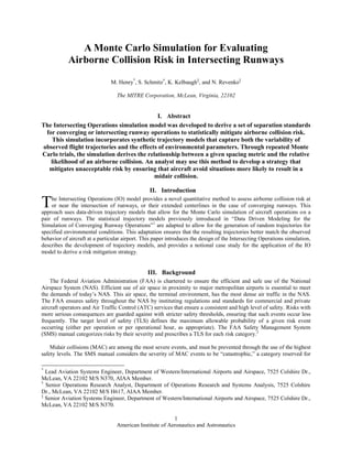
  • 14. American Institute of Aeronautics and Astronautics 14 Additional simulation batches will continue to run until this convergence metric is sufficiently small or the maximum number of simulations is reached. The simulation can also dynamically adjust batch sizes depending on the degree of convergence of the quantile estimates. V. Notional Case Study This notional case study demonstrates the experimental design and workflow for the IO model. This example analyzes a single set of converging operations; however, a holistic case study would examine all of the impacts of possible interactions within an airport’s desired configuration. The following section starts by illustrating the setup of the theoretical case; it describes the configuration, as well as the operational and environmental inputs utilized by the IO model. We then discuss how the simulation progresses under the provided inputs. Furthermore, we describe how simulation outputs are utilized to develop a controller mitigation strategy. In this case, an Arrival Departure Window is evaluated for the example scenario. A. Case This case study evaluates an example case of a departure interaction with a converging missed approach. Both runways are 7,000 feet in length and are positioned orthogonally. The runway configuration for this case study is illustrated in Figure 5. Aircraft trajectories are allowed a maximum heading change of 5 degrees. The intersection point of the arrival runway’s extended centerline with that of the departure runway, lies over the departure runway’s surface. This configuration presents the common scenario where the arriving aircraft would not interact with the departing aircraft if the arriving aircraft lands safely. The probability of a missed approach represents the risk to the departing aircraft. For the theoretical case presented here, we approximate the missed approach rate to be one-in- one-thousand. Figure 5. Runway geometries for notional airport Missed Approach Departure 7,000 ft 7,000 ft 2,500 ft 600 ft
  • 15. American Institute of Aeronautics and Astronautics 15 Figure 6. Percentage of fleet mix by aircraft type The fleet mix for the case is representative of that of a 7,000 foot runway within the NAS. Figure 6 provides a histogram of the ten most frequent aircraft types. The DH8A is a prominent aircraft type in this analysis; this is a small propeller aircraft which has significantly different performance from other more common jets in the NAS. The DH8A’s markedly different performance profile from other aircraft can have a distinct effect on the outcome of the simulation. Due to the effects of performance variation by aircraft, empirical data for the fleet mix is used whenever possible. Controllers may wish to restrict an operation based on an aircraft type. B. Environmental Data The theoretical case study uses environmental data associated with the weather observed in the east coast region of the NAS. Winds are mild, with 91% of observations below 15 knots. The airport’s altitude lies at 20 feet above mean sea level and temperatures fluctuate between -4 and 30 degrees Celsius. Figure 7 shows the temperatures over the course of a calendar year. Figure 8 provides a wind rose describing the wind directions and magnitudes of the observed winds. Figure 7. Local temperature range in a calendar year (°C) 0.0% 5.0% 10.0% 15.0% A319 DH8A E170 CRJ2 CRJ7 A320 E135 E145 B752 MD82 -20 -10 0 10 20 30 40 50 60 1/1 2/1 3/1 4/1 5/1 6/1 7/1 8/1 9/1 10/1 11/112/1
  • 16. American Institute of Aeronautics and Astronautics 16 Figure 8. Local range of winds in a calendar year To be representative of real-world airport operations, the IO model limits extreme wind speeds. The restrictions for this case are set to 25 knots of maximum head wind, 8 knots of maximum tail wind and 20 knots of maximum cross wind. While operations may occur outside of these bounds, the intent is to ensure that the simulation operates within nominal conditions in which the runway configuration is likely to occur. C. Simulation The IO model is a Monte Carlo simulation that requires numerous iterations to converge to a statistically significant result. Within the analysis presented in this paper, the goal is to find the bounds of the ADW. Therefore, convergence of the lower and upper bounds of the Arrival-Departure Window is determined over the course of the simulation. To evaluate if additional simulations will change the ADW dimensions; the evolution of the bounds is observed for the last 70 percent of the simulation. The bounds are said to sufficiently converge once the standard deviation of the bounds becomes small enough; signaling a sufficient degree of precision. To estimate the bounds within a tenth of a nautical mile we require that the standard deviation be within five hundredths of a nautical mile. To better illustrate this concept, consider Figure 9 below. Wind Speed (kts)
  • 17. American Institute of Aeronautics and Astronautics 17 Figure 9. Illustration of simulation convergence over time Figure 9 depicts the simulation evolution of an Intersecting Operations model run with 1 million model iterations. The horizontal axis provides iteration count. The vertical axis represents the distance in nautical miles with respect to arrival runway threshold. Positive values indicate distances measured before the runway threshold as the arrival was approaching, while negative values are distances measured after the runway threshold. The bounds of the ADW are evaluated at frequent intervals during the simulation and are depicted within the figure. The upper line represents the value of the approximated ADW’s upper bound, and the lower line represents the approximated ADW’s lower bound. At the start of the simulation, with a relatively small number of TCVs observed, the confidence in the fitted distribution is low. As the simulation continues, additional information on quantity and characteristics of TCVs is collected. The Arrival-Departure Window bounds stabilize and the standard deviation of the bounds decreases. The above depiction of the ADW does not constitute the final proposed bounds. This evaluation is done with a preliminary distribution fit. The goal is to determine if there exists enough simulation data to accurately provide parameter analysis during post processing. The final analysis incorporates the capabilities of the analyst utilizing statistical tools to provide a thorough evaluation of the risk environment. Standard Deviation < 0.05
  • 18. American Institute of Aeronautics and Astronautics 18 D. Simulation Output Analysis Once the simulation completes a sufficient number of iterations and precisely estimates Arrival-Departure bounds, the ADW is calculated using simulation outputs. Simulation output data that the analyst needs to derive an ADW include: (1) total number of iterations completed during simulation, (2) total number of iterations that resulted in a Target Criterion Violation (these two numbers are needed to calculate the probability of a TCV), and (3) a set of arriving aircraft locations filtered for arriving and departing aircraft which came within 500 feet of each other. The analyst fits a theoretical distribution to (3) and determines the ADW bounds as described within the post-processing section. A distribution fit to the simulation output from the case study is presented in Figure 10. Figure 10. Histogram and fitted distribution of simulated TCVs (NM) Table 1. Summary statistics of simulation output The best fit to the TCV dataset of missed approach locations at the time of a departure is provided by the Johnson SL distribution. The Shapiro-Wilk goodness-of-fit test produces a p-value of 0.76, as seen in Table 1. Comparing this value to our significance level of 0.05, we fail to reject the null hypothesis that the dataset of arriving aircraft locations is coming from the Johnson SL distribution. We proceed by evaluating the distribution ADW Summary Statistics Mean 0.48907 Standard Deviation 0.27549 Standard Error Mean 0.00864 Upper 95% Mean 0.50602 Lower 95% Mean 0.47212 N 1017 Quantiles: Uncentered and Unscaled Percentile Quantile 0.0004916 -0.27904 0.9995084 1.55811 Shapiro-Wilk Goodness-of-Fit Test W Prob<W 0.998827 0.7609 Note: Ho = The data is from the Johnson SL distribution. Small p-values reject Ho.
  • 19. American Institute of Aeronautics and Astronautics 19 quantiles that correspond to the percentiles found from the risk equation. The positions of the quantiles represent the lower and upper bounds of the ADW. The number of iterations completed in the theoretical case was 1,000,000. The number of simulations that resulted in a Target Criterion Violation was 1,017. The assumed missed approach rate was one-in-one-thousand. The Target Level of Safety was 10-9 . Solving for the risk mitigation term results in the following: ( ) ( ) The lower bound of the ADW is given by the quantile representing half of this probability, 4.916-4 . The ADW upper bound is similarly determined by the quantile representing a probability of (1-4.916-4 ). The distances corresponding to these two quantiles are 0.28 NM after the arrival runway threshold and 1.56 NM before the arrival runway threshold. The resulting ADW is depicted in Figure 11. Figure 11. Illustration of case study arrival departure window VI. Conclusion It has been shown that the IO model is an effective method for assessing the risk of terminal airspace NMAC events for operations with intersecting or converging runways. This model accurately allows for analysts to ensure that a consistent target level of safety is met for these operations through the calibration of various risk mitigation strategies, such as an Arrival Departure Window. Regression and Principal Component Analysis are used to create a trajectory model that characterizes the spectrum of flight variability in speed and altitude for given environments. When the trajectory model is applied to a specific case, the simulated flights accurately represent the speed and altitude of local traffic, making these models effective for simulating terminal airspace NMAC risk events. ADW 1.56 NM -0.28 NM Missed Approach Departure 7,000 ft 7,000 ft 2,500 ft 600 ft 1.84 NM
  • 20. American Institute of Aeronautics and Astronautics 20 The notional case study presented in this paper illustrates the application of the IO model to an analysis of departures and missed approaches on converging runways. The development of mitigation strategies designed to prevent terminal airspace NMAC events is an ongoing effort within CAASD. VII. Acknowledgments The authors would like to thank Adric Eckstein for providing peer review of this paper. Additionally, for Adric Eckstein and Joe Clements for developing the initial flight trajectory modeling construct that allows for this work to be possible. We would also like to thank John Lebron, Gregory Chesterton and Shweta Mulcare for their guidance and copy-editing throughout the writing process. VIII. Disclaimer The contents of this material reflect the views of the author and/or the Director of the Center for Advanced Aviation System Development. Neither the Federal Aviation Administration nor the Department of Transportation makes any warranty or guarantee, or promise, expressed or implied, concerning the content or accuracy of the views expressed herein. Approved for Public Release; Distribution Unlimited. 13-2900 ©2013-The MITRE Corporation. All rights reserved.
  • 21. American Institute of Aeronautics and Astronautics 21 IX. References 1 Eckstein, A., “Data Driven Modeling for the Simulation of Converging Runway Operations,” Fourth International Conference on Research in Air Transportation (ICRAT), ICRAT, Budapest, Hungary, 2010, pp. 3-10. 2 Federal Aviation Administration, Air Traffic Organization. (2005, May 24). Air Traffic Organization, Safety Management System Manual. Retrieved July 6, 2013, from Federal Avaiation Document Library: http://www.faa.gov/air_traffic/publications/media/atosmsmanualversion2-1_05-27-08_final.pdf 3 Federal Aviation Administration. (2013, March 7). Aeronatical Information Manual. Retrieved July 6, 2013, from http://www.faa.gov/air_traffic/publications/atpubs/aim/aim0706.html 4 Kunzi, F., and Hansman, R. J. (2011). Mid-Air Collision Risk and Areas of High Benefit for Traffic. AIAA Aviation Technology, Integration, and Operations Conference. Virginia Beach, VA: AIAA. Retrieved from http://www.avidyne.com/downloads/products/ads-b/MIT.Kunzi.MidAirs.pdf 5 Federal Aviation Administration, Air Traffic Organization Policy, “Order JO 7110.65U,” FAA, 2012. Federal Aviation Administration Document Library [online document database], URL: http://www.faa.gov/documentlibrary/media/order/atc.pdf [cited 26 July 2013]. 6 Federal Aviation Administration, “Press Release – ‘STARS’ Shines in Cincinnati FAA Deploys Cornerstone of Air Traffic Modernization in Cincinnati,” 2005, June 30, http://www.faa.gov/news/press_releases/news_story.cfm?newsId=6643&print=go 7 Federal Aviation Administration. (2010). Fact Sheet – Airport Surface Detection Equipment, Model X (ASDE-X). Washington, D.C.: Federal Aviation Administration. http://www.faa.gov/news/fact_sheets/news_story.cfm?newsId=6296 8 Benjamin, S.G., D. Devenyi, S.S. Weygandt, K.J. Brundage, J.M. Brown, G.A. Grell, D. Kim, B.E. Schwartz, T.G. Smirnova, T.L. Smith, and G.S. Manikin, 2004: An hourly assimilation/forecast cycle: The RUC. Monthly Weather Review., 132, 495-518 (Feb. issue). http://ruc.noaa.gov/pdf/MWR-RUC-1hcyc-Sept03-final.pdf 9 Liang, Y. C., Lee, H.P., Lim, S. P., Lin, W. Z., Lee, K. H., and Wu, C. G., “Proper Orthogonal Decomposition and Its Applications – Part I: Theory,” Journal of Sound and Vibration, Vol. 252, No. 3, 2002, pp. 527-544.