Recommended

Recommended
More Related Content
What's hot
What's hot (20)
Viewers also liked
Viewers also liked (10)
Similar to 4yp exhibition posterfinal
Similar to 4yp exhibition posterfinal (20)
4yp exhibition posterfinal
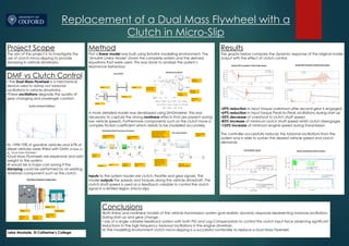
- 1. Replacement of a Dual Mass Flywheel with a Clutch in Micro-Slip Project Scope The aim of the project is to investigate the use of clutch micro-slipping to provide damping in vehicle drivetrains. Results The graphs below compare the dynamic response of the original model output with the effect of clutch control. •39% reduction in input torque overshoot after second gear is engaged •69% reduction in input torque Peak-to-Peak oscillations during start up •25% decrease of overshoot in clutch shaft speed •83% increase of minimum clutch shaft speed whilst clutch disengages •133% increase of minimum engine speed during transmission The controller successfully reduces the torsional oscillations from the system and is able to sustain the desired vehicle speed and clutch demands. DMF vs Clutch Control • The Dual Mass Flywheel is a mechanical device used to damp out torsional oscillations in vehicle drivetrains. •These oscillations degrade the quality of gear changing and passenger comfort. •In 1998 75% of gasoline vehicles and 67% of diesel vehicles were fitted with DMFs (W.Reik et al. ‘Dual Mass Flwheels’. •Dual Mass Flywheels are expensive and add weight to the system. •It would be a major cost saving if the damping could be performed by an existing drivetrain component such as the clutch. Conclusions •Both linear and nonlinear models of the vehicle transmission system give realistic dynamic response representing torsional oscillations during start up and gear change. • Use of a single variable feedback system with both PID and Lag Compensators to control the clutch input force observing significant reductions to the high frequency torsional oscillations in the engine drivetrain. •In the modelling environment clutch micro-slipping is a successful contender to replace a Dual Mass Flywheel. Method First a linear model was built using Simulink modelling environment. The ‘Simulink Linear Model’ shows the complete system and the derived equations that were used. This was done to analyse the system’s resonance behaviour. A more detailed model was developed using SimDriveline. This was necessary to capture the strong nonlinear effects that are present during low vehicle speeds. Furthermore components such as the clutch have a complex friction coefficient which needs to be modelled accurately. Inputs to the system model are clutch, throttle and gear signals. The model outputs the speeds and torques along the vehicle driveshaft. The clutch shaft speed is used as a feedback variable to control the clutch signal in a limited region (micro-slip). Leke Abolade, St Catherine’s College