SlideShare ist ein Scribd-Unternehmen logo
1 von 15
Geo Optics
LEOT 330
Exam 2
Michelle Schroth
2. Autocollimation is an optical setup where a collimated beam (of parallel light
rays) leaves an optical system and is reflected back into the same system by a
plane mirror. Collimated.
It is used for measuring small tilting angles of the mirror, see autocollimator, or
for testing the quality of the optical system or of a part of it. One special applica-
tion is to determine the focal length of a diverging lens.


3. a. The equivalent power and focal length of the following system is 8 m-1 and
12.5 cm.

F1sys = f1× f2 ∕f1 + f2 - (d∕n)
        = 20 cm × 20 cm ∕20 cm + 20 cm - (8 cm∕1)
        = 12.5 cm
F1sys = F2sys = 12.5 cm

Pequ = P1 + P2 - P1 × P2 × d
       = 5 m-1 + 5m-1 - (5 m-1) (5 m-1) (0.08 m)
       = 8 m-1
3. b. The front vertex power and the front vertex focal length are 13.34 d (m-1)
and 7.5 cm. The back vertex power and the back vertex focal length are
13.34 d (m-1) and 7.5 cm.
P = 1∕f                                                         f1 = 20 cm = .20 m
P = 5 m-1                                                       f2 = 20 cm = .20 m
P = 5 m-1                                                        d = 8 cm = 0.08 m
                                                                               n=1
PFv = P1 + P2∕1 - P2 (d∕n)
    = 5 m-1 + 5m-1 (0.08 m-1∕1)
    = 13.34 d (m-1)

fFv = 1∕PFv = 1∕13.34 m-1 = 0.075 m = 7.5 cm

PFv = PBv = 13.34 d (m-1)

fFv = fBv = 1∕13.34 m-1 = 0.075 m = 7.5 cm


3. c. The location of the principal planes H1 and H2 are shown below.

4. Five common types of optical aberrations are:
Spherical
Which is an optical effect observed in an optical device (lens,mirror, etc.) that oc-
curs due to the increased refraction of light rays when they strike a lens or a re-
flection of light rays when they strike a mirror near its edge, in comparison with
those that strike nearer the center. It signifies a deviation of the device from the
normal operation, i.e., it results in an imperfection of the produced image.
For single lens, spherical aberration can be controlled by bending the lens into its
best form. Also for multiple lenses, spherical aberrations can be canceled by
overcorrecting some elements. The use of symmetric doublets greatly reduce
spherical aberrations.


Chromatic Aberration
Chromatic aberration or "color fringing" is caused by the camera lens not focus-
ing different wavelengths of light onto the exact same focal plane (the focal
length for different wavelengths is different) and/or by the lens magnifying differ-
ent wavelengths differently. These types of chromatic aberration are referred to
as "Longitudinal Chromatic Aberration" and "Lateral Chromatic Aberration" re-
spectively and can occur concurrently. The amount of chromatic aberration de-
pends on the dispersion of the glass. A lens will not focus different colors in ex-
actly the same place because the focal length depends on refraction and the in-
dex of refraction for blue light (short wavelengths) is larger than that of red light
(long wavelengths). The amount of chromatic aberration depends on the disper-
sion of the glass.
One way to minimize this aberration is to use glasses of different dispersion in a
doublet or other combination.


The use of a strong positive lens made from a low dispersion glass like crown
glass coupled with a weaker high dispersion glass like flint glass can correct the
chromatic aberration for two colors, e.g., red and blue.


Field Curvature
Is where the sharpest focus of the lens is on a curved surface in the image space
rather than a plane. Objects in the center and edges of the field are never in fo-
cus simultaneously.
We can correct this aberration by using specially designed objectives. These
specially-corrected objectives have been named plan or plano (for flat-field)
and are the most common type of objective in use today, providing ocular fields
ranging between 18 and 26 millimeters, which exhibit sharp detail from center to
edge.


Comatic Aberrations

They are seen mainly with off-axis light fluxes and are most severe when the mi-
croscope is out of alignment. With a comatic aberration, the image of a point is
focused at sequentially differing heights producing a series of asymmetrical spot
shapes of increasing size that result in a comet-like shape to the Airy pattern.
The distinct shape displayed by images with comatic aberration is a result of re-
fraction differences by light rays passing through the various lens zones as the
incident angle increases. The severity of comatic aberration is a function of thin
lens shape, causing meridional rays passing through the periphery of the lens to
arrive at the image plane closer to the axis than do rays passing nearer the axis
and closer to the principal ray.


When the Off-Axis Distance slider is moved to the far right position, the ray trace
diagram shows several skewed light ray paths representing those rays involved
in the aberration. Off-axis light rays often interfere with each other near the focal
plane to generate malformed images seen in the microscope. The image point
produced by a comatic aberration is actually a complicated three-dimensional
asymmetrical diffraction pattern that departs from the classical Airy pattern.
What is formed is an elongated structure composed of arcs and ellipsoidal inten-
sities that only vaguely resemble the disk-ring arrangement from which the point
spread function evolved.
The severity of Coma is heavily dependent upon the shape of the lens. A strong-
ly concave positive meniscus lens will demonstrate substantial negative comatic
aberration, whereas plano-convex and bi-convex lenses produce comas that
range from slightly negative to zero. Objects imaged through the convex side of
a plano-convex lens or a convex meniscus lens will have a positive coma.
Coma can be corrected by using a combination of lenses that are positioned
symmetrically around a central stop. In order to completely eliminate coma, the
Abbe sine condition must be fulfilled:
                              d' × n(sinβ') = d × n(sinβ')
where d' and d are the distances from the optical axis in the image space (prime
values) and object space, n is the refractive index, and β is the viewing angle. A
lens system, such as a microscope condenser or objective, which is free of co-
matic aberration is referred to as aplanatic.


Astigmatic Aberration
An objective lens for which spherical and coma aberrations have been corrected
may not be able to converge object points off the axis to a point, separating those
points into a segment image in a concentric direction and that in a radial direc-
tion. This aberration is known as "astigmatic aberration". An objective with any
astigmatic aberration will change the blur orientation of a point image to longitudi-
nal or lateral with respect to before or after the focal point.
When an object lies an appreciable distance from the optical axis, the incident
cone of rays will strike the lens asymmetrically, giving rise to the aberration
known as astigmatism. To describe it, picture the plane which contains both the
chief ray, which is the ray which passes through the center of the lens, and the
optical axis. This plane is knows as the meridional, or tangential, plane. The
sagittal plane is defined as the plane containing the chief ray which is also per-
pendicular to the tangential plane.
When the object is on the optical axis, the cone of rays is symmetrical with re-
spect to the spherical surfaces of the lens. In this case the meridional and the
sagittal planes are the same, and the ray configurations in all the planes contain-
ing the optical axis are identical. In the absence of any spherical aberration, all
of the focal lengths are the same and all of the rays arrive at a single focus.
When the object is located off axis, the rays come into the lens at an oblique an-
gle. Now the configuration of the ray bundle will be different in the meridional
and sagittal planes. Because of this, the focal lengths in these planes will be dif-
ferent as well. Basically, the meridional rays are tilted more with respect to the
lens than the sagittal rays, and thus have a shorter focal length. Using Fermat's
principal, we find that the focal length difference depends effectively on the pow-
er of the lens and the angle at which the rays are inclined. This is known as the
astigmatic difference, and it increases rapidly as the rays become more oblique.
Since there are two distinct focal lengths, the incident conical bundle of rays
changes after being refracted. The cross section of the beam as it leaves the
lens is initially circular, but it gradually becomes elliptical with the major axis in
the sagittal plane, until at the tangential focus, FT, the ellipse degenerates into a
line (at third order). All the rays from the object traverse this line, which is known
as the primary image. Beyond this point the beam's cross section rapidly opens
out until it is again circular. At that location the image is a circular blur known as
the circle of least confusion. Moving further from the lens, the beam's cross sec-
tion again deforms into a line, called the secondary image. This time it is in the
meridional plane at the sagittal focus, FS.


5. Find the location of the image in the following diagram. If the object is 2 cm in
height, determine the image height. Indicate whether the image is upright of in-
verted.
Lens 1
             do = -20 cm
1∕do + 1∕f = 1∕di                         M = hi∕ho
1∕-20 cm + 1∕10 cm = 1∕di                    = di∕do
20 cm = di                       = 20 cm∕-20 cm
                               M = -1 (Inverted)


hi = (ho) × (m)
  = (2 cm) × (-1)
hi = -2


Lens 2
 do = 10 cm
          1∕do + 1∕f = 1∕di    M = hi∕ho
1∕10 cm + 1∕-30 cm =              = di∕do
                  15 cm = di        = 15 cm∕10 cm
                                 M = 1.5 (Upright)


Lens 3 is a Mirror.
                  do = 12 cm
          1∕do + 1∕f = 1∕di       M = hi∕ho
1∕12 cm + 1∕10 cm =                  = di∕do
              5.5 cm = di              = 5.5 cm ∕12 cm
                                    M = 0.458 or .46 (Upright)


hi = (ho) × (m)
  = (-3 cm) ×(0.458)
hi = 1.374 or 1.4 cm


The image is upright and the image height is 1.4 cm.


6. See attachment.
7. Using the Lens-makers equation, design a double-convex glass lens with a fo-
cal length of 60 cm. Assume the refractive index of the glass is 1.50.


P = 1∕f
  = 1∕60 cm
  = 1∕.6 m
P = 1.67 d (m-1)
R2 = -2R1
Use the Lens makers formula
P = 1.67 m-1 = (n-1)(1∕R1 - 1∕R2)
               = (1.50 - 1)(1∕R1 - 1∕-2R1)
               = (0.5)(1∕R1 - 1∕R1)
               = (0.5) 1∕R1 [1 + 1∕2]
               = (0.5) (1∕R1) [1.5]
    1.67 m-1 = (.75)∕R1
            R1 = .75∕167 m-1
               = 0.45 m
            R1 = 45 cm


R2 = -2R1
   = -2 × (45 cm)
R2 = - 90 cm


8. a. Optical dispersion is the phenomenon in which the phase velocity of a wave
depends on its frequency, or alternatively when the group velocity depends on
the frequency. Media having such a property are termed dispersive media. Opti-
cal dispersion is sometimes called chromatic dispersion to emphasize its wave-
length-dependent nature, or group-velocity dispersion (GVD) to emphasize the
role of the group velocity.
The most familiar example of chromatic dispersion is a rainbow, in which disper-
sion causes the spatial separation of a white light into components of different
wavelengths i.e. different colors.
Chromatic dispersion is especially important to researchers who are designing
optical equipment like cameras, optical microscopes, and telescopes. When a
lens system is not carefully designed, the system will focus different colors of
light at different spots – and this doesn’t give a very good image! By planning the
system carefully and using a combination of lenses made out of different materi-
als with different indices of refraction, these chromatic aberrations can be greatly
minimized.
The effect of chromatic dispersion is also important to people who send short
pulses, which are made up of many different wavelengths, through optical
waveguides, like optical fiber. Short pulses of EM Rad are used as a way of en-
coding data, like voices during a telephone call and the information on this web-
site, so that the data can be sent from one place to another. As the pulse travels
in the waveguide, some wavelengths of light travel faster than others. As the
pulses travel down the waveguide, they increase in width and overlap with one
another. If they spread too much, it is difficult to tell where one pulse begins and
the other ends, and this results in information being lost. Researchers who work
in the Communications and Fiber Optics fields of optics are developing devices
to combat the effects of dispersion.


The dispersion of light by glass prisms is used to construct spectrometers and
spectroadiometers. Holographic gratings are also used, as they allow more ac-
curate discrimination of wavelengths.
8. b. Principal planes in optical systems
The two principal planes in a lens system are hypothetical and have the property
that a ray emerging from the lens appears to have crossed the rear principal
plane at the same distance from the axis that that ray appeared to cross the front
principal plane, as viewed from the front of the lens. This means that the lens can
be treated as if all of the refraction happened at the principal planes.
The principal planes are crucial in defining the optical properties of the system,
since it is the distance of the object and image from the front and rear principal
planes that determines the magnification of the system.
If the medium surrounding the optical system has a refractive index of 1 (e.g., air
or vacuum), then the distance from the principal planes to their corresponding fo-
cal points is just the focal length of the system. In the more general case, the dis-
tance to the foci is the focal length multiplied by the index of refraction of the
medium.
For a thin lens in air, the principal planes both lie at the location of the lens. The
point where they cross the optical axis is sometimes misleadingly called the opti-
cal center of the lens. However, that for a real lens the principal planes do not
necessarily pass through the centre of the lens, and may not lie inside the lens at
all.
For a given set of lenses and separations, the principal planes are fixed and do
not depend upon the object position. The thin lens equation can be used, but it
leaves out the distance between the principal planes. The focal length f is that
given by Gullstrand’s equation. The principal planes for a thick lens are illustrat-
ed. For practical use, it is often useful to use the front and back vertex powers.

Weitere ähnliche Inhalte

Was ist angesagt?

Was ist angesagt? (20)

Ophthalmic prism
Ophthalmic prismOphthalmic prism
Ophthalmic prism
 
Prism & it's uses
Prism & it's uses Prism & it's uses
Prism & it's uses
 
The Prism
The PrismThe Prism
The Prism
 
Prisms
PrismsPrisms
Prisms
 
Prisms
Prisms Prisms
Prisms
 
Prism
PrismPrism
Prism
 
Phase
PhasePhase
Phase
 
Beam profile
Beam profileBeam profile
Beam profile
 
Real prism use in ophthalmology
Real prism use in ophthalmologyReal prism use in ophthalmology
Real prism use in ophthalmology
 
Abberations of refractive error
Abberations of refractive errorAbberations of refractive error
Abberations of refractive error
 
Treating with prism
Treating with prismTreating with prism
Treating with prism
 
04 prism
04 prism 04 prism
04 prism
 
Prism therapy in orthoptics
Prism therapy in orthopticsPrism therapy in orthoptics
Prism therapy in orthoptics
 
Ophthalmology 5th year, 3rd lecture (Dr. Tara)
Ophthalmology 5th year, 3rd lecture (Dr. Tara)Ophthalmology 5th year, 3rd lecture (Dr. Tara)
Ophthalmology 5th year, 3rd lecture (Dr. Tara)
 
Astigmatic lens used in ophthalmology and eye
Astigmatic lens used in ophthalmology and eyeAstigmatic lens used in ophthalmology and eye
Astigmatic lens used in ophthalmology and eye
 
Cardinal points,thin lenses and thick lenses
Cardinal points,thin lenses and thick lensesCardinal points,thin lenses and thick lenses
Cardinal points,thin lenses and thick lenses
 
Ray Optics Class 12 Part-1
Ray Optics Class 12 Part-1Ray Optics Class 12 Part-1
Ray Optics Class 12 Part-1
 
Prism in ophthalmology
Prism in ophthalmologyPrism in ophthalmology
Prism in ophthalmology
 
Optometric optics
Optometric opticsOptometric optics
Optometric optics
 
Refraction of light at spherical surfaces of lenses
Refraction of light at spherical surfaces of lensesRefraction of light at spherical surfaces of lenses
Refraction of light at spherical surfaces of lenses
 

Ähnlich wie geo exam2W

Lenses
LensesLenses
Lensesozo120
 
Sci 1010 chapter 7
Sci 1010 chapter 7Sci 1010 chapter 7
Sci 1010 chapter 7stanbridge
 
Reflection and refraction at home & curved surfaces
Reflection and refraction at home & curved surfacesReflection and refraction at home & curved surfaces
Reflection and refraction at home & curved surfacesMohammad Arman Bin Aziz
 
Light full chaptet 10 cbse x
Light full chaptet 10 cbse x Light full chaptet 10 cbse x
Light full chaptet 10 cbse x RAVNEET NAGI
 
Electromagnetic waves option g review
Electromagnetic waves option g reviewElectromagnetic waves option g review
Electromagnetic waves option g reviewjsawyer3434
 
Lens and Mirrors [Autosaved] for Grade 10.pptx
Lens and Mirrors [Autosaved] for Grade 10.pptxLens and Mirrors [Autosaved] for Grade 10.pptx
Lens and Mirrors [Autosaved] for Grade 10.pptxMaamKatrynTan
 
Chapter Light: Grade 10 Physics
Chapter Light: Grade 10 PhysicsChapter Light: Grade 10 Physics
Chapter Light: Grade 10 PhysicsLearn Infinite
 
Review of geometric optics
Review of geometric opticsReview of geometric optics
Review of geometric opticsSalalKhan5
 
LIGHT , REFACTION AND REFRACTION CLASS 10TH
LIGHT , REFACTION AND REFRACTION CLASS 10TH LIGHT , REFACTION AND REFRACTION CLASS 10TH
LIGHT , REFACTION AND REFRACTION CLASS 10TH Ajay Chikte
 
Sesión de Laboratorio 6: Lentes Ópticas
Sesión de Laboratorio 6: Lentes ÓpticasSesión de Laboratorio 6: Lentes Ópticas
Sesión de Laboratorio 6: Lentes ÓpticasJavier García Molleja
 
Physics-Light form 4
Physics-Light form 4Physics-Light form 4
Physics-Light form 4Fatini Adnan
 
Refraction - Ray Optics - Physics - Light chapter - class 7 and 8
Refraction - Ray Optics - Physics - Light chapter - class 7 and 8Refraction - Ray Optics - Physics - Light chapter - class 7 and 8
Refraction - Ray Optics - Physics - Light chapter - class 7 and 8AbishekThiyagarajan
 
unit2 interference & diffraction
unit2 interference & diffractionunit2 interference & diffraction
unit2 interference & diffractionnitw
 
Reflection and Mirrors
Reflection and MirrorsReflection and Mirrors
Reflection and Mirrorsitutor
 

Ähnlich wie geo exam2W (20)

Lenses
LensesLenses
Lenses
 
Sci 1010 chapter 7
Sci 1010 chapter 7Sci 1010 chapter 7
Sci 1010 chapter 7
 
Reflection and refraction at home & curved surfaces
Reflection and refraction at home & curved surfacesReflection and refraction at home & curved surfaces
Reflection and refraction at home & curved surfaces
 
Angle of view - photography
Angle of view -  photographyAngle of view -  photography
Angle of view - photography
 
Light full chaptet 10 cbse x
Light full chaptet 10 cbse x Light full chaptet 10 cbse x
Light full chaptet 10 cbse x
 
Electromagnetic waves option g review
Electromagnetic waves option g reviewElectromagnetic waves option g review
Electromagnetic waves option g review
 
Lens and Mirrors [Autosaved] for Grade 10.pptx
Lens and Mirrors [Autosaved] for Grade 10.pptxLens and Mirrors [Autosaved] for Grade 10.pptx
Lens and Mirrors [Autosaved] for Grade 10.pptx
 
Chapter Light: Grade 10 Physics
Chapter Light: Grade 10 PhysicsChapter Light: Grade 10 Physics
Chapter Light: Grade 10 Physics
 
Review of geometric optics
Review of geometric opticsReview of geometric optics
Review of geometric optics
 
Mirrors.pptx
Mirrors.pptxMirrors.pptx
Mirrors.pptx
 
LIGHT , REFACTION AND REFRACTION CLASS 10TH
LIGHT , REFACTION AND REFRACTION CLASS 10TH LIGHT , REFACTION AND REFRACTION CLASS 10TH
LIGHT , REFACTION AND REFRACTION CLASS 10TH
 
Sesión de Laboratorio 6: Lentes Ópticas
Sesión de Laboratorio 6: Lentes ÓpticasSesión de Laboratorio 6: Lentes Ópticas
Sesión de Laboratorio 6: Lentes Ópticas
 
Physics-Light form 4
Physics-Light form 4Physics-Light form 4
Physics-Light form 4
 
Lenses in Optics
Lenses in OpticsLenses in Optics
Lenses in Optics
 
Refraction - Ray Optics - Physics - Light chapter - class 7 and 8
Refraction - Ray Optics - Physics - Light chapter - class 7 and 8Refraction - Ray Optics - Physics - Light chapter - class 7 and 8
Refraction - Ray Optics - Physics - Light chapter - class 7 and 8
 
unit2 interference & diffraction
unit2 interference & diffractionunit2 interference & diffraction
unit2 interference & diffraction
 
Optics geometry
Optics geometryOptics geometry
Optics geometry
 
Module No. 37
Module No. 37Module No. 37
Module No. 37
 
Reflection and Mirrors
Reflection and MirrorsReflection and Mirrors
Reflection and Mirrors
 
Interferometers
InterferometersInterferometers
Interferometers
 

Kürzlich hochgeladen

business environment micro environment macro environment.pptx
business environment micro environment macro environment.pptxbusiness environment micro environment macro environment.pptx
business environment micro environment macro environment.pptxShruti Mittal
 
Traction part 2 - EOS Model JAX Bridges.
Traction part 2 - EOS Model JAX Bridges.Traction part 2 - EOS Model JAX Bridges.
Traction part 2 - EOS Model JAX Bridges.Anamaria Contreras
 
Lucia Ferretti, Lead Business Designer; Matteo Meschini, Business Designer @T...
Lucia Ferretti, Lead Business Designer; Matteo Meschini, Business Designer @T...Lucia Ferretti, Lead Business Designer; Matteo Meschini, Business Designer @T...
Lucia Ferretti, Lead Business Designer; Matteo Meschini, Business Designer @T...Associazione Digital Days
 
Driving Business Impact for PMs with Jon Harmer
Driving Business Impact for PMs with Jon HarmerDriving Business Impact for PMs with Jon Harmer
Driving Business Impact for PMs with Jon HarmerAggregage
 
Onemonitar Android Spy App Features: Explore Advanced Monitoring Capabilities
Onemonitar Android Spy App Features: Explore Advanced Monitoring CapabilitiesOnemonitar Android Spy App Features: Explore Advanced Monitoring Capabilities
Onemonitar Android Spy App Features: Explore Advanced Monitoring CapabilitiesOne Monitar
 
Supercharge Your eCommerce Stores-acowebs
Supercharge Your eCommerce Stores-acowebsSupercharge Your eCommerce Stores-acowebs
Supercharge Your eCommerce Stores-acowebsGOKUL JS
 
Go for Rakhi Bazaar and Pick the Latest Bhaiya Bhabhi Rakhi.pptx
Go for Rakhi Bazaar and Pick the Latest Bhaiya Bhabhi Rakhi.pptxGo for Rakhi Bazaar and Pick the Latest Bhaiya Bhabhi Rakhi.pptx
Go for Rakhi Bazaar and Pick the Latest Bhaiya Bhabhi Rakhi.pptxRakhi Bazaar
 
1911 Gold Corporate Presentation Apr 2024.pdf
1911 Gold Corporate Presentation Apr 2024.pdf1911 Gold Corporate Presentation Apr 2024.pdf
1911 Gold Corporate Presentation Apr 2024.pdfShaun Heinrichs
 
Appkodes Tinder Clone Script with Customisable Solutions.pptx
Appkodes Tinder Clone Script with Customisable Solutions.pptxAppkodes Tinder Clone Script with Customisable Solutions.pptx
Appkodes Tinder Clone Script with Customisable Solutions.pptxappkodes
 
GUIDELINES ON USEFUL FORMS IN FREIGHT FORWARDING (F) Danny Diep Toh MBA.pdf
GUIDELINES ON USEFUL FORMS IN FREIGHT FORWARDING (F) Danny Diep Toh MBA.pdfGUIDELINES ON USEFUL FORMS IN FREIGHT FORWARDING (F) Danny Diep Toh MBA.pdf
GUIDELINES ON USEFUL FORMS IN FREIGHT FORWARDING (F) Danny Diep Toh MBA.pdfDanny Diep To
 
1911 Gold Corporate Presentation Apr 2024.pdf
1911 Gold Corporate Presentation Apr 2024.pdf1911 Gold Corporate Presentation Apr 2024.pdf
1911 Gold Corporate Presentation Apr 2024.pdfShaun Heinrichs
 
Cybersecurity Awareness Training Presentation v2024.03
Cybersecurity Awareness Training Presentation v2024.03Cybersecurity Awareness Training Presentation v2024.03
Cybersecurity Awareness Training Presentation v2024.03DallasHaselhorst
 
20200128 Ethical by Design - Whitepaper.pdf
20200128 Ethical by Design - Whitepaper.pdf20200128 Ethical by Design - Whitepaper.pdf
20200128 Ethical by Design - Whitepaper.pdfChris Skinner
 
Introducing the Analogic framework for business planning applications
Introducing the Analogic framework for business planning applicationsIntroducing the Analogic framework for business planning applications
Introducing the Analogic framework for business planning applicationsKnowledgeSeed
 
Pitch Deck Teardown: Xpanceo's $40M Seed deck
Pitch Deck Teardown: Xpanceo's $40M Seed deckPitch Deck Teardown: Xpanceo's $40M Seed deck
Pitch Deck Teardown: Xpanceo's $40M Seed deckHajeJanKamps
 
Cyber Security Training in Office Environment
Cyber Security Training in Office EnvironmentCyber Security Training in Office Environment
Cyber Security Training in Office Environmentelijahj01012
 
Technical Leaders - Working with the Management Team
Technical Leaders - Working with the Management TeamTechnical Leaders - Working with the Management Team
Technical Leaders - Working with the Management TeamArik Fletcher
 
Unveiling the Soundscape Music for Psychedelic Experiences
Unveiling the Soundscape Music for Psychedelic ExperiencesUnveiling the Soundscape Music for Psychedelic Experiences
Unveiling the Soundscape Music for Psychedelic ExperiencesDoe Paoro
 
Jewish Resources in the Family Resource Centre
Jewish Resources in the Family Resource CentreJewish Resources in the Family Resource Centre
Jewish Resources in the Family Resource CentreNZSG
 
Excvation Safety for safety officers reference
Excvation Safety for safety officers referenceExcvation Safety for safety officers reference
Excvation Safety for safety officers referencessuser2c065e
 

Kürzlich hochgeladen (20)

business environment micro environment macro environment.pptx
business environment micro environment macro environment.pptxbusiness environment micro environment macro environment.pptx
business environment micro environment macro environment.pptx
 
Traction part 2 - EOS Model JAX Bridges.
Traction part 2 - EOS Model JAX Bridges.Traction part 2 - EOS Model JAX Bridges.
Traction part 2 - EOS Model JAX Bridges.
 
Lucia Ferretti, Lead Business Designer; Matteo Meschini, Business Designer @T...
Lucia Ferretti, Lead Business Designer; Matteo Meschini, Business Designer @T...Lucia Ferretti, Lead Business Designer; Matteo Meschini, Business Designer @T...
Lucia Ferretti, Lead Business Designer; Matteo Meschini, Business Designer @T...
 
Driving Business Impact for PMs with Jon Harmer
Driving Business Impact for PMs with Jon HarmerDriving Business Impact for PMs with Jon Harmer
Driving Business Impact for PMs with Jon Harmer
 
Onemonitar Android Spy App Features: Explore Advanced Monitoring Capabilities
Onemonitar Android Spy App Features: Explore Advanced Monitoring CapabilitiesOnemonitar Android Spy App Features: Explore Advanced Monitoring Capabilities
Onemonitar Android Spy App Features: Explore Advanced Monitoring Capabilities
 
Supercharge Your eCommerce Stores-acowebs
Supercharge Your eCommerce Stores-acowebsSupercharge Your eCommerce Stores-acowebs
Supercharge Your eCommerce Stores-acowebs
 
Go for Rakhi Bazaar and Pick the Latest Bhaiya Bhabhi Rakhi.pptx
Go for Rakhi Bazaar and Pick the Latest Bhaiya Bhabhi Rakhi.pptxGo for Rakhi Bazaar and Pick the Latest Bhaiya Bhabhi Rakhi.pptx
Go for Rakhi Bazaar and Pick the Latest Bhaiya Bhabhi Rakhi.pptx
 
1911 Gold Corporate Presentation Apr 2024.pdf
1911 Gold Corporate Presentation Apr 2024.pdf1911 Gold Corporate Presentation Apr 2024.pdf
1911 Gold Corporate Presentation Apr 2024.pdf
 
Appkodes Tinder Clone Script with Customisable Solutions.pptx
Appkodes Tinder Clone Script with Customisable Solutions.pptxAppkodes Tinder Clone Script with Customisable Solutions.pptx
Appkodes Tinder Clone Script with Customisable Solutions.pptx
 
GUIDELINES ON USEFUL FORMS IN FREIGHT FORWARDING (F) Danny Diep Toh MBA.pdf
GUIDELINES ON USEFUL FORMS IN FREIGHT FORWARDING (F) Danny Diep Toh MBA.pdfGUIDELINES ON USEFUL FORMS IN FREIGHT FORWARDING (F) Danny Diep Toh MBA.pdf
GUIDELINES ON USEFUL FORMS IN FREIGHT FORWARDING (F) Danny Diep Toh MBA.pdf
 
1911 Gold Corporate Presentation Apr 2024.pdf
1911 Gold Corporate Presentation Apr 2024.pdf1911 Gold Corporate Presentation Apr 2024.pdf
1911 Gold Corporate Presentation Apr 2024.pdf
 
Cybersecurity Awareness Training Presentation v2024.03
Cybersecurity Awareness Training Presentation v2024.03Cybersecurity Awareness Training Presentation v2024.03
Cybersecurity Awareness Training Presentation v2024.03
 
20200128 Ethical by Design - Whitepaper.pdf
20200128 Ethical by Design - Whitepaper.pdf20200128 Ethical by Design - Whitepaper.pdf
20200128 Ethical by Design - Whitepaper.pdf
 
Introducing the Analogic framework for business planning applications
Introducing the Analogic framework for business planning applicationsIntroducing the Analogic framework for business planning applications
Introducing the Analogic framework for business planning applications
 
Pitch Deck Teardown: Xpanceo's $40M Seed deck
Pitch Deck Teardown: Xpanceo's $40M Seed deckPitch Deck Teardown: Xpanceo's $40M Seed deck
Pitch Deck Teardown: Xpanceo's $40M Seed deck
 
Cyber Security Training in Office Environment
Cyber Security Training in Office EnvironmentCyber Security Training in Office Environment
Cyber Security Training in Office Environment
 
Technical Leaders - Working with the Management Team
Technical Leaders - Working with the Management TeamTechnical Leaders - Working with the Management Team
Technical Leaders - Working with the Management Team
 
Unveiling the Soundscape Music for Psychedelic Experiences
Unveiling the Soundscape Music for Psychedelic ExperiencesUnveiling the Soundscape Music for Psychedelic Experiences
Unveiling the Soundscape Music for Psychedelic Experiences
 
Jewish Resources in the Family Resource Centre
Jewish Resources in the Family Resource CentreJewish Resources in the Family Resource Centre
Jewish Resources in the Family Resource Centre
 
Excvation Safety for safety officers reference
Excvation Safety for safety officers referenceExcvation Safety for safety officers reference
Excvation Safety for safety officers reference
 

geo exam2W

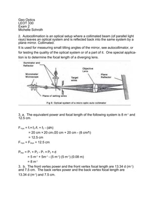
  • 1. Geo Optics LEOT 330 Exam 2 Michelle Schroth 2. Autocollimation is an optical setup where a collimated beam (of parallel light rays) leaves an optical system and is reflected back into the same system by a plane mirror. Collimated. It is used for measuring small tilting angles of the mirror, see autocollimator, or for testing the quality of the optical system or of a part of it. One special applica- tion is to determine the focal length of a diverging lens. 3. a. The equivalent power and focal length of the following system is 8 m-1 and 12.5 cm. F1sys = f1× f2 ∕f1 + f2 - (d∕n) = 20 cm × 20 cm ∕20 cm + 20 cm - (8 cm∕1) = 12.5 cm F1sys = F2sys = 12.5 cm Pequ = P1 + P2 - P1 × P2 × d = 5 m-1 + 5m-1 - (5 m-1) (5 m-1) (0.08 m) = 8 m-1 3. b. The front vertex power and the front vertex focal length are 13.34 d (m-1) and 7.5 cm. The back vertex power and the back vertex focal length are 13.34 d (m-1) and 7.5 cm.
  • 2. P = 1∕f f1 = 20 cm = .20 m P = 5 m-1 f2 = 20 cm = .20 m P = 5 m-1 d = 8 cm = 0.08 m n=1 PFv = P1 + P2∕1 - P2 (d∕n) = 5 m-1 + 5m-1 (0.08 m-1∕1) = 13.34 d (m-1) fFv = 1∕PFv = 1∕13.34 m-1 = 0.075 m = 7.5 cm PFv = PBv = 13.34 d (m-1) fFv = fBv = 1∕13.34 m-1 = 0.075 m = 7.5 cm 3. c. The location of the principal planes H1 and H2 are shown below. 4. Five common types of optical aberrations are: Spherical Which is an optical effect observed in an optical device (lens,mirror, etc.) that oc- curs due to the increased refraction of light rays when they strike a lens or a re- flection of light rays when they strike a mirror near its edge, in comparison with those that strike nearer the center. It signifies a deviation of the device from the normal operation, i.e., it results in an imperfection of the produced image.
  • 3. For single lens, spherical aberration can be controlled by bending the lens into its best form. Also for multiple lenses, spherical aberrations can be canceled by overcorrecting some elements. The use of symmetric doublets greatly reduce spherical aberrations. Chromatic Aberration Chromatic aberration or "color fringing" is caused by the camera lens not focus- ing different wavelengths of light onto the exact same focal plane (the focal length for different wavelengths is different) and/or by the lens magnifying differ- ent wavelengths differently. These types of chromatic aberration are referred to as "Longitudinal Chromatic Aberration" and "Lateral Chromatic Aberration" re- spectively and can occur concurrently. The amount of chromatic aberration de- pends on the dispersion of the glass. A lens will not focus different colors in ex- actly the same place because the focal length depends on refraction and the in- dex of refraction for blue light (short wavelengths) is larger than that of red light (long wavelengths). The amount of chromatic aberration depends on the disper- sion of the glass.
  • 4. One way to minimize this aberration is to use glasses of different dispersion in a doublet or other combination. The use of a strong positive lens made from a low dispersion glass like crown glass coupled with a weaker high dispersion glass like flint glass can correct the chromatic aberration for two colors, e.g., red and blue. Field Curvature Is where the sharpest focus of the lens is on a curved surface in the image space rather than a plane. Objects in the center and edges of the field are never in fo- cus simultaneously.
  • 5. We can correct this aberration by using specially designed objectives. These specially-corrected objectives have been named plan or plano (for flat-field) and are the most common type of objective in use today, providing ocular fields ranging between 18 and 26 millimeters, which exhibit sharp detail from center to edge. Comatic Aberrations They are seen mainly with off-axis light fluxes and are most severe when the mi- croscope is out of alignment. With a comatic aberration, the image of a point is focused at sequentially differing heights producing a series of asymmetrical spot shapes of increasing size that result in a comet-like shape to the Airy pattern.
  • 6. The distinct shape displayed by images with comatic aberration is a result of re- fraction differences by light rays passing through the various lens zones as the incident angle increases. The severity of comatic aberration is a function of thin lens shape, causing meridional rays passing through the periphery of the lens to arrive at the image plane closer to the axis than do rays passing nearer the axis and closer to the principal ray. When the Off-Axis Distance slider is moved to the far right position, the ray trace diagram shows several skewed light ray paths representing those rays involved in the aberration. Off-axis light rays often interfere with each other near the focal plane to generate malformed images seen in the microscope. The image point produced by a comatic aberration is actually a complicated three-dimensional asymmetrical diffraction pattern that departs from the classical Airy pattern. What is formed is an elongated structure composed of arcs and ellipsoidal inten- sities that only vaguely resemble the disk-ring arrangement from which the point spread function evolved. The severity of Coma is heavily dependent upon the shape of the lens. A strong- ly concave positive meniscus lens will demonstrate substantial negative comatic aberration, whereas plano-convex and bi-convex lenses produce comas that range from slightly negative to zero. Objects imaged through the convex side of a plano-convex lens or a convex meniscus lens will have a positive coma. Coma can be corrected by using a combination of lenses that are positioned symmetrically around a central stop. In order to completely eliminate coma, the Abbe sine condition must be fulfilled: d' × n(sinβ') = d × n(sinβ') where d' and d are the distances from the optical axis in the image space (prime values) and object space, n is the refractive index, and β is the viewing angle. A
  • 7. lens system, such as a microscope condenser or objective, which is free of co- matic aberration is referred to as aplanatic. Astigmatic Aberration An objective lens for which spherical and coma aberrations have been corrected may not be able to converge object points off the axis to a point, separating those points into a segment image in a concentric direction and that in a radial direc- tion. This aberration is known as "astigmatic aberration". An objective with any astigmatic aberration will change the blur orientation of a point image to longitudi- nal or lateral with respect to before or after the focal point.
  • 8. When an object lies an appreciable distance from the optical axis, the incident cone of rays will strike the lens asymmetrically, giving rise to the aberration known as astigmatism. To describe it, picture the plane which contains both the chief ray, which is the ray which passes through the center of the lens, and the optical axis. This plane is knows as the meridional, or tangential, plane. The sagittal plane is defined as the plane containing the chief ray which is also per- pendicular to the tangential plane. When the object is on the optical axis, the cone of rays is symmetrical with re- spect to the spherical surfaces of the lens. In this case the meridional and the sagittal planes are the same, and the ray configurations in all the planes contain- ing the optical axis are identical. In the absence of any spherical aberration, all of the focal lengths are the same and all of the rays arrive at a single focus. When the object is located off axis, the rays come into the lens at an oblique an- gle. Now the configuration of the ray bundle will be different in the meridional and sagittal planes. Because of this, the focal lengths in these planes will be dif- ferent as well. Basically, the meridional rays are tilted more with respect to the lens than the sagittal rays, and thus have a shorter focal length. Using Fermat's principal, we find that the focal length difference depends effectively on the pow- er of the lens and the angle at which the rays are inclined. This is known as the astigmatic difference, and it increases rapidly as the rays become more oblique.
  • 9. Since there are two distinct focal lengths, the incident conical bundle of rays changes after being refracted. The cross section of the beam as it leaves the lens is initially circular, but it gradually becomes elliptical with the major axis in the sagittal plane, until at the tangential focus, FT, the ellipse degenerates into a line (at third order). All the rays from the object traverse this line, which is known as the primary image. Beyond this point the beam's cross section rapidly opens out until it is again circular. At that location the image is a circular blur known as the circle of least confusion. Moving further from the lens, the beam's cross sec- tion again deforms into a line, called the secondary image. This time it is in the meridional plane at the sagittal focus, FS. 5. Find the location of the image in the following diagram. If the object is 2 cm in height, determine the image height. Indicate whether the image is upright of in- verted. Lens 1 do = -20 cm 1∕do + 1∕f = 1∕di M = hi∕ho 1∕-20 cm + 1∕10 cm = 1∕di = di∕do
  • 10. 20 cm = di = 20 cm∕-20 cm M = -1 (Inverted) hi = (ho) × (m) = (2 cm) × (-1) hi = -2 Lens 2 do = 10 cm 1∕do + 1∕f = 1∕di M = hi∕ho 1∕10 cm + 1∕-30 cm = = di∕do 15 cm = di = 15 cm∕10 cm M = 1.5 (Upright) Lens 3 is a Mirror. do = 12 cm 1∕do + 1∕f = 1∕di M = hi∕ho 1∕12 cm + 1∕10 cm = = di∕do 5.5 cm = di = 5.5 cm ∕12 cm M = 0.458 or .46 (Upright) hi = (ho) × (m) = (-3 cm) ×(0.458)
  • 11. hi = 1.374 or 1.4 cm The image is upright and the image height is 1.4 cm. 6. See attachment. 7. Using the Lens-makers equation, design a double-convex glass lens with a fo- cal length of 60 cm. Assume the refractive index of the glass is 1.50. P = 1∕f = 1∕60 cm = 1∕.6 m P = 1.67 d (m-1)
  • 12. R2 = -2R1 Use the Lens makers formula P = 1.67 m-1 = (n-1)(1∕R1 - 1∕R2) = (1.50 - 1)(1∕R1 - 1∕-2R1) = (0.5)(1∕R1 - 1∕R1) = (0.5) 1∕R1 [1 + 1∕2] = (0.5) (1∕R1) [1.5] 1.67 m-1 = (.75)∕R1 R1 = .75∕167 m-1 = 0.45 m R1 = 45 cm R2 = -2R1 = -2 × (45 cm) R2 = - 90 cm 8. a. Optical dispersion is the phenomenon in which the phase velocity of a wave depends on its frequency, or alternatively when the group velocity depends on the frequency. Media having such a property are termed dispersive media. Opti- cal dispersion is sometimes called chromatic dispersion to emphasize its wave- length-dependent nature, or group-velocity dispersion (GVD) to emphasize the role of the group velocity. The most familiar example of chromatic dispersion is a rainbow, in which disper- sion causes the spatial separation of a white light into components of different wavelengths i.e. different colors.
  • 13. Chromatic dispersion is especially important to researchers who are designing optical equipment like cameras, optical microscopes, and telescopes. When a lens system is not carefully designed, the system will focus different colors of light at different spots – and this doesn’t give a very good image! By planning the system carefully and using a combination of lenses made out of different materi- als with different indices of refraction, these chromatic aberrations can be greatly minimized. The effect of chromatic dispersion is also important to people who send short pulses, which are made up of many different wavelengths, through optical waveguides, like optical fiber. Short pulses of EM Rad are used as a way of en- coding data, like voices during a telephone call and the information on this web- site, so that the data can be sent from one place to another. As the pulse travels in the waveguide, some wavelengths of light travel faster than others. As the pulses travel down the waveguide, they increase in width and overlap with one another. If they spread too much, it is difficult to tell where one pulse begins and the other ends, and this results in information being lost. Researchers who work in the Communications and Fiber Optics fields of optics are developing devices to combat the effects of dispersion. The dispersion of light by glass prisms is used to construct spectrometers and spectroadiometers. Holographic gratings are also used, as they allow more ac- curate discrimination of wavelengths.
  • 14. 8. b. Principal planes in optical systems The two principal planes in a lens system are hypothetical and have the property that a ray emerging from the lens appears to have crossed the rear principal plane at the same distance from the axis that that ray appeared to cross the front principal plane, as viewed from the front of the lens. This means that the lens can be treated as if all of the refraction happened at the principal planes. The principal planes are crucial in defining the optical properties of the system, since it is the distance of the object and image from the front and rear principal planes that determines the magnification of the system. If the medium surrounding the optical system has a refractive index of 1 (e.g., air or vacuum), then the distance from the principal planes to their corresponding fo- cal points is just the focal length of the system. In the more general case, the dis- tance to the foci is the focal length multiplied by the index of refraction of the medium. For a thin lens in air, the principal planes both lie at the location of the lens. The point where they cross the optical axis is sometimes misleadingly called the opti- cal center of the lens. However, that for a real lens the principal planes do not necessarily pass through the centre of the lens, and may not lie inside the lens at all.
  • 15. For a given set of lenses and separations, the principal planes are fixed and do not depend upon the object position. The thin lens equation can be used, but it leaves out the distance between the principal planes. The focal length f is that given by Gullstrand’s equation. The principal planes for a thick lens are illustrat- ed. For practical use, it is often useful to use the front and back vertex powers.