Catalog mikro mikro mk301a-user-dienhathe.vn
•
0 likes•67 views

Xem thêm tại website : http://tailieukythuat.info

Recommended
More Related Content
What's hot
What's hot (16)
Similar to Catalog mikro mikro mk301a-user-dienhathe.vn
Similar to Catalog mikro mikro mk301a-user-dienhathe.vn (20)
More from Dien Ha The
More from Dien Ha The (20)
Recently uploaded
Recently uploaded (20)
Catalog mikro mikro mk301a-user-dienhathe.vn
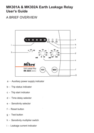
- 1. MK301A & MK302A Earth Leakage Relay User’s Guide A BRIEF OVERVIEW a - Auxiliary power supply indicator b - Trip status indicator c - Trip start indicator d - Time delay selector e - Sensitivity selector f - Reset button e f g a b c d h i g - Test button h - Sensitivity multiplier switch i - Leakage current indicator
- 2. TECHNICAL DATA 1. Light Indicators The light indicators display the status of the system. Indicator AUX TRIP DELAY Status Off Off Off No auxiliary power supply On Off Off System normal, no tripping On Off On Trip start, time delay countdown started On On Off Earth leakage tripped The earth leakage indicators indicate the amount of leakage current detected and are expressed as percentage of the set current. i) Status indicators ii) Leakage indicators* 10% - leakage current 10% of set current 20% - leakage current 20% of set current 40% - leakage current 40% of set current 60% - leakage current 60% of set current 80% - leakage current 80% of set current 2. Sensitivity Adjustment The MK301A/MK302A features 2 rotary selector switches for sensitivity setting: (i) 9 position sensitivity selector(e) offer setting range of 30mA, 50mA, 75mA, 100mA, 125mA, 150mA, 200mA, 250mA and 300mA. (ii) 3 position sensitivity multiplier selector (h) switch offer selection of 1x, 10x and 100x. * FOR MK302A MODEL ONLY On On Blink ZCT not connected 3. Tripping Delay Time Adjustment • The 9 position time delay selector ( d ) provides additional delay for fault discrimination. • Selectable delays are: Instantaneous (no delay), 50ms, 100ms, 150ms, 250ms, 350ms, 500ms, 1s and 3s.
- 3. 4. Push Button Reset Button • The reset button is for resetting the light indicator and the latching trip contact after a trip has occured. • To reset, press the reset button once. Test Button • Press the test button to simulate an earth leakage trip condition. 5. Remote Control Input* Remote Test Input • This digital input is similiar to the TEST push-button. To remotely test the relay, make a connection between terminals 11 and 13 of the relay Remote Reset Input • This digital input is to remotely reset the relay when tripped. To reset the relay, make a connection between terminals 12 and 13 of the relay. 6. Output Contact Trip Contact • This is a latching type contact. It operates when tripped. Safety Contact * • Contact energized when supply is connected and the relay is functioning normally. 7. Settings Sensitivity adjustment 0.03 A to 30 A Delay time adjustment 0 sec to 3.0 sec 8. Contacts Contact arrangement 1 x latching type with manual reset 1 x safety contact* NC and NO contacts available Contact rating 5A, 250VAC (cos ϕ =1) contact rating Contact material Silver alloy Expected electrical life 100,000 operations at rated current Expected mechanical life 5 million operations * FOR MK302A MODEL ONLY : : : : : : : : : 9. Inputs Remote Test/Reset Inputs*: N.O. dry input Auxiliary supply MK301A-240A 198~265 VAC MK302A-240A MK301A-110A 90~120 VAC MK302A-110A Rated frequency 50 or 60 Hz VA rating 3VA typical : : : : : : Setting accuracy -15% to +0% Timing accuracy 5% : :±
- 4. 10. Indicators Auxiliary supply Green colour LED indicator Time delay Red colour LED indicator Trip Red colour LED indicator Real time leakage Red colour LED indicator current : : : : 11.Zero-phase Current Transformer To operate with ZCT series of current transformer MK 302A TRIP CONTACT SAFETY CONTACT* REMOTE TEST* REMOTE RESET* LO AD L1 L2 L3 N CO N TACTO R MK 301A or MK302A TRIP CONTACT LO AD L1 L2 L3 N SHUN T TRIP Side 96 mm 96mm Front 90mm 70mm 90mm 90mm 12. Mechanical Mounting method Panel mounting Front panel Standard DIN96mmx96mm Approximate weight 0.6kg (exclude ZCT) 13. Connection Diagram 14. Case Dimensions * FOR MK302A MODEL ONLY : : :